|
|

| PROFILE No | FOR SYNCHRONOUS PSTN LINES |
40 41 42 43 44 | PSTN back-up V.25bis SBS PSTN back-up V.25bis EBS PSTN back-up V.25bis SBS + XID PSTN back-up V.25bis EBS + XID PSTN back-up 108/1 SBS |
| PROFILE No | FOR VIP LINES |
50 | VIP STATION ADDRESS |
| PROFILE No | FOR BSC 3270 LINES |
60 | BSC 3270 STATION ADDRESS |
| PROFILE No | FOR BSC 2780/3780 LINES |
70 | BSC 27/3780 STATION ADDRESS |
| PROFILE No | FOR ASYNCHRONOUS PSTN LINES |
45 46 | PSTN V.25bis PAD PSTN V.25bis VIDEOTEX |
| PROFILE No | FOR ASYNCHRONOUS LINES |
00 01 02 03 04 05 06 07 08 09 10 11 12 13 14 15 16 17 20 21 22 23 30 32 48 49 80 84 89 90 91 | Plain terminal Transparent terminal or LSCP LSCP Terminal communicating with LSCP Same as profile 03 with send time-out and padding Terminal with control by PAD Same as profile 00 with special break Data transmission terminal with "CR" and break Same as profile 05 with echo Telex terminals Same as profile 05 without control by PAD Same as profile 02 without control by PAD Same as profile 00 without echo Block mode terminal controlled by PAD without send time-out Same as profile 13 with authorized DLE Same as profile 13 without control Host HEWLETT PACKARD Terminal HEWLETT PACKARD Same as profile 00 with control and teleprinter-adapted editing Same as profile 20 with display-terminal adapted editing Same as profile 13 with control by DTE-C Same as profile 21 for data base application VIDEOTEX terminal Multi-standard VIDEOTEX terminal S.L.I.P. protocol P.P.P. Protocol Specific customer profile (class 14) LMI Special terminal Plain terminal without padding or send time-out Plain transparent LSCP |
| PROFILE No | FOR BSC-T LINES |
100 102 | STANDARD BSC-T TPC DRM |
| PROFILE No | FOR FRCE; FRTE FRAME RELAY LINES |
84 | LMI |
| PROFILE No | FOR FRCE; FRTE FRAME RELAY LINES |
47 | X.31 Case B on D Channel |
| PARAMETERS No. | ASYNCHRONOUS CONNECTION |
0 1 2 3 4 5 6 7 8 9 10 11 12 13 14 15 16 17 18 19 20 21 22 | Profile No. (See the beginning of this chapter) Recall of PAD or escape character Echo Data forwarding character Idle Timer Delay Control of terminal by PAD Transmission of indications by PAD Reaction of PAD on break signal from DTE Discard of output data Padding after CR Line folding DTE speed Control of PAD by terminal LF insertion after CR Padding after linefeed Editing Character delete Line delete Line display Editing PAD service signal Echo mask Parity management Page wait |
| PARAMETERS No. | PSTN ASYNCHRONOUS CONNECTION |
0 1 2 3 4 5 6 7 8 9 10 11 12 13 14 15 16 17 18 19 20 21 22 23 24 25 26 27 28 29 30 31 | Profile No. (See beginning of this chapter) Recall of PAD or escape character Echo Data forwarding character Idle timer delay Control of terminal by PAD Transmission of indications by PAD Reaction of PAD on break signal from DTE Discard of output data Padding after CR Line folding DTE speed Control of PAD by terminal LF insertion after CR Padding after linefeed Editing Character delete Line delete Line display Editing PAD service signal Echo mask Parity management Page wait Asynchronous protocol type Call mode (108/1, 108/2) Supervision time-out (establishment of switched link) Inactivity time-out of the switched connection Modem bit rate Time-out monitoring a dial attempt on the PSTN Number of dial attempts Type of input/output Number of modem initialization strings |
Recall: specifies which character must be sent to escape from the Data Transfer Mode to the PAD Command Mode. The character mostly used is the DLE (Data Link Escape) character. Usually DLE is transmitted by pressing Ctrl-P on the keyboard.
0 = | no escape character |
1 = | DLE is escape character |
32...126 = | ASCII code of escape character. |
Echo: Specifies whether the PAD echoes the data from the asynchronous device or not.
0 = | no echo |
1 = | echo of characters transmitted by DTE-C (terminal). |
Data forwarding character: specifies which characters received from the asynchronous device are used to complete and forward a packet. There is also the possibility of choosing a time-out, set by the Idle Timer Delay.
0= | no data forwarding character |
2 = | (CR) |
6 = | (CR), (ESC), (BEL), (ENQ), (ACK) |
18 = | (CR), (EOT), (ETX) |
32 = | The characters HT, LF, VT and FF are data forwarding characters |
126 = | all check characters are data forwarding characters |
127 = | all characters in columns 0 and 1 and CHARACTER DEL are data forwarding characters |
128 = | same as 126: all VIDEOTEX "function keys", except CONNEXION/FIN, are data forwarding characters. |
Idle Timer Delay: specifies the maximum time interval between two successive characters received from the asynchronous device. When the PAD does not receive a next character within the specified time, it will complete the packet and forward it to the network.
0 = | no data forwarding by time-out |
1 to 250 = | time-out value in units of 0.05 s (rounded-off to next higher value). |
Recommendation: The value of this parameter should be higher than the time needed to receive a block of n characters (n is defined in C12P33).
Example: on an asynchronous line, 1200 bit/s with C12R33 = 128: parameter 4 should be 22 minimum.
Ancillary device control: this corresponds to the flow control of the asynchronous device by the PAD. The PAD may indicate whether it is ready or not to accept more characters from the asynchronous device by transmitting X-On or X-Off characters.
0 = | no control |
1 = | control by XON-XOFF (during transfer) |
2 = | control by XON-XOFF in the command (or waiting for command) phase |
8 = | control by RTS-CTS (during transfer). |
Control of PAD service signals: specifies if the PAD may send or not PAD service signals to the asynchronous device.
0 = | no indication |
1 = | indications + welcome page |
5 = | indications + welcome page + cursor |
9 = | indications + welcome page + indications in clear language |
13 = | indications + welcome page + indications in clear language + cursor. |
All values different from 0, transmit facilities and call data.
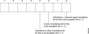
Indications + welcome page (mandatory bit for this to be accepted: bit 0 = 1)
Cursor (mandatory bit for this to be accepted: bit 0 = 1)
Indications in clear (mandatory bit for this to be accepted: bit 0 = 1)
Reaction of PAD on break signals: specifies the behavior of the PAD Transfer Mode on reception of a break signal from the asynchronous device.
0 = | break is only a data forwarding signal |
1 = | interrupt |
2 = | reset |
5 = | reset, Break indication |
8 = | command prefix |
21 = | interrupt, Break indication, stop data delivery. |
Discard Output: specifies if the PAD should discard the contents of received data packets rather than disassembling and transmitting them to the asynchronous device.
0 = | the PAD transmits the data from the DTE-P to the DTE-C |
1 = | the PAD destroys the data from the DTE-P. |
Padding after carriage return: used by the PAD for providing an automatic insertion of padding characters in the data stream sent towards the asynchronous device after a Carriage Return.
0 = | no padding |
1 to 250 = | number of zeros inserted after CR. |
Line folding: Used by the PAD for providing the automatic insertion of a Carriage Return and Line Feed characters in the data stream sent towards the asynchronous device after a predetermined maximum number of characters.
0 = | no folding |
1 to 250 = | number of displayable characters displayed on a line before folding. |
DTE speed: specifies the access rate between the PAD and the asynchronous device.
00 = | 110 bit/s |
01 = | 134.5 bit/s |
02 = | 300 bit/s |
03 = | 1200 bit/s |
04 = | 600 bit/s |
05 = | 75 bit/s |
06 = | 150 bit/s |
07 = | 1800 bit/s |
08 = | 200 bit/s |
09 = | 100 bit/s |
10 = | 50 bit/s |
11 = | 75/1200 bit/s |
12 = | 2400 bit/s |
13 = | 4800 bit/s |
14 = | 9600 bit/s |
15 = | 19200 bit/s |
16-18-19 = | 19200 bit/s |
17 = | 57600 bit/s |
20 = | 38400 bit/s |
21 = | 1200/75 bit/s |
22 = | 115200 bit/s |
Flow control of PAD: this corresponds to the flow control of the PAD by the asynchronous device. The asynchronous device may indicate whether it si ready or not to accept more characters from the asynchronous device by transmitting X-ON or X-OFF characters.
0 = | no flow control |
1 = | slaving of PAD by XON-OFF |
8 = | slaving of PAD by RTS/CTS (see note at parameter 5, value 8). |
Line Feed Insertion after Carriage Return: Used by the PAD (in Data Transfer Mode) for providing an automatic insertion of a Line Feed character in the data stream sent towards the asynchronous device after a Carriage Return.
0 = | no insertion |
1 = | insertion of LF after each CR of a character string sent to the DTE-C |
2 = | insertion of LF after each CR from the DTE-C |
4 = | insertion of LF after each CR returned as echo to DTE-C |
3, 5, 6, 7 = | combination of the above values. |
Padding after linefeed: used by the PAD (in Data Transfer Mode) for providing an automatic insertion of padding characters in the data stream sent towards the asynchronous device after a Line Feed.
0 = | no padding |
1 to 250 = | number of (nulls) inserted after linefeed. |
Editing: specifies if the user is able to edit the input data (delete character, delete line and display line) before it is assembled into a packet and transmitted.
0 = | no editing in data transfer |
1 = | editing in data transfer. |
Editing is the acceptance of parameters 16, 17, 18.
Delete character: specifies which character is used for character delete.
0 to 127 = | ASCII code of character used as delete character. |
128 = | ASCII code of character used as delete character for Minitel M1B. |
Line delete: specifies which character is used for line delete.
0 to 127 = | ASCII code of character used as line delete character. |
128 = | ASCII code of character used as delete character for Minitel M1B. |
Line display: specifies which character is used for line display.
0 to 127 = | ASCII code of character used as line display character. |
Editing PAD service signals: specifies whether or not editing PAD Service Signals are transmitted to the synchronous device and in which format.
0 = | no editing to DTE-C |
1 = | Editing for printing terminal |
2 = | Editing for display terminal |
Echo mask: Used to select a predefined set of character(s) that should not be echoes in case the echo function is turned off (see Parameter 2).
0 = | no echo |
1 = | no echo of CR |
2 = | no echo of LF |
4 = | no echo of VT, HT, FF |
8 = | no echo of BEL, BS |
16 = | no echo of ESC, ENQ |
32 = | no echo of ACK, NACK, STX, SOH, EOT, ETB, ETX |
64 = | no echo of editing characters |
128 = | no echo of non-significant characters not mentioned for the other values. |
All combinations of these values are possible.
Parity management: specifies whether or not the PAD performs a parity check on the characters received from/or transmitted to the asynchronous device.
0 = | no management |
3 = | management. |
The value of the parity is indicated in class 12, parameter 28.
Page wait: allows the PAD to suspend the characters transmission to the asynchronous device after a predetermined maximum number of Line Feed has been transmitted by the PAD.
0 = | no waiting |
n (1 to 127) = | wait (end of page) after n lines on the screen. |
Type of PSTN asynchronous protocol.
0 = | reserved |
1 = | asynchronous V.25bis |
2 = | Hayes. |
Call mode.
1 = | reserved |
2 = | addressed (108/2) (by default). |
In address mode, the switching equipment supplies the telephone number.
Supervision time-out (establishment of switched link).
0 to 254 (units of 1 sec).
This time-out is activated when the first call packet is on the PSTN line. It is inactivated when the statistics function notices that the line is in service. When the time-out expires, the call is cleared.
Inactivity time-out of the switched connection.
0 to 254 (steps of 1 sec).
This time-out is activated when there are no virtual circuits used on a line. When the time-out expires and there are still no virtual circuits used, the line is taken down. In case a virtual circuit has been opened, the monitoring time continues for 1 second.
Value 0 means that this mechanism is not activated.
Modem bit rate.
0 | = | 150 | bit/s | 4 | = | 2400 | bit/s |
1 | = | 300 | bit/s | 8 | = | 4800 | bit/s |
2 | = | 600 | bit/s | 10 | = | 9600 | bit/s |
3 | = | 75/1200 | bit/s* | 11 | = | 19200 | bit/s.
|
*75 transmission
1200 reception— terminal end
The other characteristics of the dialogue are:
Time-out monitoring a dial attempt on the PSTN.
0 to 250 (unit = 10 s).
This time-out is activated at each PSTN dial attempt. It is inactivated when the connection is established or when a modem error message is received. When the time-out expires, a new dial attempt is made after a time-out of three seconds.
The number of dial attempts multiplied by this time-out plus 30 seconds should not exceed the value of parameter 25. If this is the case, the switched link is inactivated when the time-out of parameter 3 expires.
Number of dial attempts.
0 to 250.
Type of input/output
EBA: asynchronous standardized input (DCE defined P1 C12)
SBA: asynchronous standardized output (DTE defined P1 C12).
Remark: It concerns the direction of the call and it serves to establish the physical circuit.
00 = | EBA/SBA |
01 = | EBA |
02 = | SBA. |
Number of modem initialization strings (see C20-R0).
0 = | no string |
1 to 3 = | parameter of recurrence 0. |
| PARAMETERS NO. | SYNCHRONOUS CONNECTION |
0 1 2 3 4 5 6 7 8 9 10 11 12 13 | Profile number (see beginning of this chapter) Asynchronous protocol type in command mode Call mode (108/1, 108/2) Supervision time-out (switched link establishment) Inactivity time-out Modem bit rate Time-out monitoring a dial attempt on PSTN Number of dial attempts Type of input/output Number of modem initialization strings XID transmit XID receive Number of attempts by remote party Step of inactivity time-out |
Asynchronous protocol type in command mode.
0 = | reserved |
1 = | V.25bis asynchronous |
2 = | Hayes. |
Call mode.
1 = | direct (108/1) |
2 = | addressed (108/2) (by default). |
Supervision time-out (switched link establishment).
1 to 250 (steps of 1 sec).
This time-out is activated when the first call packet is on the PSTN line. It is inactivated when the statistics function notices that the line is in service. When the time-out expires, the call is cleared.
Inactivity time-out of the switched connection.
0 to 25. (Steps of 10 sec.).
This time-out is activated when there are no virtual circuits used on a line. When the time-out expires and there are still no virtual circuits used, the line is taken down. In case a virtual circuit has been opened, the monitoring time continues for 1 second.
Value 0 means that this mechanism is not activated. This time-out is not taken into account on level 2 disconnect request.
Modem bit rate.
0 | = | 150 | bit/s | 4 | = | 2400 | bit/s |
1 | = | 300 | bit/s | 8 | = | 4800 | bit/s |
2 | = | 600 | bit/s | 10 | = | 9600 | bit/s |
3 | = | 1200 | bit/s | 11 | = | 19200 | bit/s. |
The other characteristics of the dialogue are:
The speed of the dialogue depends on the type of modem configured with parameter 1.
Time-out monitoring a dial attempt on the PSTN.
0 to 250 (unit = 10 s).
This time-out is activated at each PSTN dial attempt. It is inactivated when the connection is established or when a modem error message is received. When the time-out expires, a new dial attempt is made after a time-out of 30 s.
Number of dial attempts.
0 to 250.
Type of input/output
EBS: synchronous standardized input (DCE defined P1 C12)
SBS: synchronous standardized output (DTE defined P1 C12).
00 = | EBS/SBS |
01 = | EBS |
02 = | SBS. |
The EBS/SBS mode is not authorized in 108/1.
Number of modem initialization strings (see C20-R0).
0 = | no string |
1 to 3 = | parameter of recurrence 0. |
This string is used to initialize the modem in Hayes mode. It is optional and it detects the presence of the modem in V.25bis mode.
Transmit of XID frame.
108/1 mode: | 0 | = no. |
| 1 to 4 | = no of frame to be transmitted (C21). |
108/2 mode: | 0 | = no. |
| 1 | = yes. |
Receive of XID frame.
0 = no
1 = yes.
Number of attempts by remote party (transmit of XID frame).
0 to 250.
Step of inactivity time-out
0 = step of 1 s
1 = step of 10 s.
| 0 | 50 | Reserved (Profile) |
|---|---|---|
1 | 0 | VIP Station Address |
2 | 1 | VIP Station Address |
3 | 2 | VIP Station Address |
4 | 3 | VIP Station Address |
5 | 4 | VIP Station Address |
6 | 5 | VIP Station Address |
7 | 6 | VIP Station Address |
8 | 7 | VIP Station Address |
9 | 8 | VIP Station Address |
10 | 9 | VIP Station Address |
11 | 10 | VIP Station Address |
12 | 11 | VIP Station Address |
13 | 12 | VIP Station Address |
14 | 13 | VIP Station Address |
15 | 14 | VIP Station Address |
16 | 15 | VIP Station Address |
17 | 16 | VIP Station Address |
18 | 17 | VIP Station Address |
91 | 18 | VIP Station Address |
20 | 91 | VIP Station Address |
21 | 20 | VIP Station Address |
22 | 21 | VIP Station Address |
23 | 22 | VIP Station Address |
24 | 23 | VIP Station Address |
25 | 24 | VIP Station Address |
26 | 25 | VIP Station Address |
27 | 26 | VIP Station Address |
28 | 27 | VIP Station Address |
29 | 28 | VIP Station Address |
30 | 29 | VIP Station Address |
31 | 30 | VIP Station Address |
32 | 31 | VIP Station Address |
| 0 | 60 | Reserved (Profile) |
|---|---|---|
1 | 0 | BSC Station Address |
2 | 1 | BSC Station Address |
3 | 2 | BSC Station Address |
4 | 3 | BSC Station Address |
5 | 4 | BSC Station Address |
6 | 5 | BSC Station Address |
7 | 6 | BSC Station Address |
8 | 7 | BSC Station Address |
9 | 8 | BSC Station Address |
10 | 9 | BSC Station Address |
11 | 10 | BSC Station Address |
12 | 11 | BSC Station Address |
13 | 12 | BSC Station Address |
14 | 13 | BSC Station Address |
15 | 14 | BSC Station Address |
16 | 15 | BSC Station Address |
17 | 16 | BSC Station Address |
18 | 17 | BSC Station Address |
91 | 18 | BSC Station Address |
20 | 91 | BSC Station Address |
21 | 20 | BSC Station Address |
22 | 21 | BSC Station Address |
23 | 22 | BSC Station Address |
24 | 23 | BSC Station Address |
25 | 24 | BSC Station Address |
26 | 25 | BSC Station Address |
27 | 26 | BSC Station Address |
28 | 27 | BSC Station Address |
29 | 28 | BSC Station Address |
30 | 29 | BSC Station Address |
31 | 30 | BSC Station Address |
32 | 31 | BSC Station Address |
Example:
| CC or Device Number | CC POLL ADDRESS Device address | CC selection ADDRESS | ||||||
| EBCDIC Character | EBCDIC (Hex) | ASCII Character | ASCII (Hex) | EBCDIC Character | EBCDIC (Hex) | ASCII Character | ASCII (Hex) | |
0 1 2 3 4 5 6 7 8 9 10 11 12 13 14 15 16 17 18 19 20 21 22 23 24 25 26 27 28 29 30 31 | space A B C D E F G H I Ç . < ( + | & J K L M N O P Q R ! $ * ) ; —| | 40 C1 C2 C3 C4 C5 C6 C7 C8 C9 4A 4B 4C 4D 4E 4F 50 D1 D2 D3 D4 D5 D6 D7 D8 D9 5A 5B 5C 5D 5E 5F | space A B C D E F G H I [ . < ( + | & J K L M N O P Q R ! $ * ) ; ^ | 20 41 42 43 44 45 46 47 48 49 5B 2E 3C 28 2B 21 26 4A 4B 4C 4D 4E 4F 50 51 52 5D 24 2A 29 3B 5E | -
S C T U V W Y Z | , % _ > ? 0 1 2 3 4 5 6 7 8 9 : # @ ` = " | 60 61 E2 E3 E4 E5 E6 E7 E8 E9 6A 6B 6C 6D 6E 6F F0 F1 F2 F3 F4 F5 F6 F7 F8 F9 7A 7B 7C 7D ;_ 7F | -
S T U V W Y Z | , % _ > ? 0 1 2 3 4 5 6 7 8 9 : # @ ` ; ^ | 2D 2F 53 54 55 56 57 58 59 5A 7C 2C 25 5F 3E 3F 30 31 32 33 34 35 36 37 38 39 3A 23 40 27 3D 22 |
| EBCDIC Character |
Profiles of class 12:
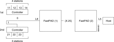
Programming of line 8 on FastPad (1) side:
Class 19 controller table:
· Class 19 parameter 42 (1st controller): | ||
| 1st byte: | 03 (No. of auto-call), see class 8 |
| 2nd byte: | 00 (1st controller address) |
| 3rd byte: | 04 (number of stations) |
| 4th byte: | 13 (position of 1st station), |
|
| class 13: extension line connection |
|
| parameters (recurrence 8) |
|
| Profile 60 (BSC 3270): |
|
| Parameter 13-11 |
|
| Parameter 14-12 |
|
| Parameter 15-13 |
|
| Parameter 16-14 |
· Class 19 parameter 43 (2nd controller): | ||
| 1st byte: | 03 (No. of auto-call), see class 8 |
| 2nd byte: | 01 (2nd controller address) |
| 3rd byte: | 03 (number of stations) |
| 4th byte: | 07 (position of 1st station), |
|
| parameter 7-21 |
|
| parameter 8-22 |
|
| parameter 9-23 |
Parameters displayed | Meaning of parameters | Possible values |
1 |
|
|
. |
|
|
. | BSC 2780/3780 | "A to Z", "a to z" |
. | Station address | and "0 to 9" |
32 |
|
|
These bytes are coded in decimal and represent the values of (A to Z), (a to z) and 0 to 9.
Example: The address (Ab 5) is coded in 3 bytes as: (Ab 5) = 65, 98, 53.
These bytes are coded in decimal and represent the values of (A to Z), (a to z) and 0 to 9.
Example: The address (Ab 5) is coded in 3 bytes as: (Ab 5) = 193, 130, 245.
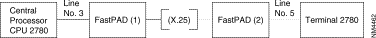
Principles for programming a BSC 2780/3780 line:
Meaning in the different classes
· v1: | position of automatic call in class 8, recurrence 0, |
· v2: | contains byte A of the identification of the terminal if the BSC 3780 protocol is used on a PSTN (XXABC ENQ). |
· v3: | contains byte B (terminal identification) if the BSC 3780 protocol is used on a PSTN (XXABC ENQ). |
· v4: | contains byte C (terminal identification) if the BSC 3780 protocol is used on a PSTN (XXABC ENQ). |
Examples of BSC 2780/3780 line configuration
· v1: | position of automatic call in C8 - R0 |
· v2: | not significant |
· v3: | not significant |
· v4: | not significant. |
· v1: | position of automatic call in C8 - R0 |
· v2: | not significant |
· v3: | not significant |
· v4: | not significant. |

| v1: | position of automatic call in C8 - R0 |
| v2: | 166 (w = A6 hexa = 166 decimal) |
| v3: | 216 (R = D8 hexa = 216 decimal) |
| v4: | 163 (t = A3 hexa = 163 decimal). |
| v1: | position of automatic call in C8 - R0 |
| v2: | 192 (A = C0 hexa = 192 decimal) |
| v3: | 193 (B = C1 hexa = 193 decimal) |
| v4: | 194 (C = C2 hexa = 194 decimal). |
| v1: | Position of automatic call in C8 - R0 |
| v2: | 227 (T = E3 hexa = 227 decimal) |
| v3: | 227 (T = E3 hexa = 227 decimal) |
| v4: | 227 (T = E3 hexa = 227 decimal). |
| v1: | position of automatic call in C8 - R0 |
| v2: | 166 (w = A6 hexa = 166 decimal) |
| v3: | 216 (R = D8 hexa = 216 decimal) |
| v4: | 163 (t = A3 hexa = 163 decimal). |
| v1: | position of automatic call in C8 - R0 |
| v2: | 192 (A = C0 hexa = 192 decimal) |
| v3: | 193 (B = C1 hexa = 193 decimal) |
| v4: | 194 (C = C2 hexa = 194 decimal). |
| v1: | Position of automatic call in C8 - R0 |
| v2: | 227 (T = E3 hexa = 227 decimal) |
| v3: | 227 (T = E3 hexa = 227 decimal) |
| v4: | 227 (T = E3 hexa = 227 decimal). |
parameters 1 to 5 | Permanent delimiters |
parameters 6 to 8 | Data frame start delimiters |
parameter 9 | Number of characters to be inhibited (1..10) |
parameters 10, 11 | Same as 6 to 8 with inhibition |
parameters 12 to 14 | Data frame terminator |
parameters 15, 16 | Control frame terminator |
parameter 17 | ACK0 (0 = no, 1 = yes) |
parameter 18 | ACK1 (0 = no, 1 = yes) |
parameter 19 | WACK (0 = no, 1 = yes) |
parameter 20 | RVI (0 = no, 1 = yes) |
parameter 21 | WABT (0 = no, 1 = yes) |
Parameters 1 to 16 (except 9) are not configured if the values is 0. The different values must be taken from the following list:
1 ENQ | 4 STX | 7 ETB | 10 DLE |
2 NAK | 5 SOH | 8 PAD | 11 ESC |
3 EOT | 6 ETX | 9 ACK | 12 BEL |
Configure ENQ with permanent delimiters, STX with data frame start delimiters and ETX with data frame terminator.
parameter 1 | : 1 |
parameters 2 to 5 | : 0 |
parameter 6 | : 4 |
parameters 7 to 8 | : 0 |
parameter 9 | : 0 |
parameters 10, 11 | : 0 |
parameter 12 | : 6 |
parameters 13 to 14 | : 0 |
parameters 15, 16 | : 0 |
parameters 17 to 21 | : 0 |
Consult profile 100 of class 13 to see the values corresponding to the normal BSC protocol.
The parameters 17 to 21 configure the bi-character control frames beginning with the DLE character.
WABT is no a BSC frame but an MSV1 frame (subsequent use).
1. Permanent delimiters (C13, P1 to 5)
2. Data frame start delimiters (C13, P6 to 8)
3. Data frame start delimiters with terminator inhibition (C13, P10 and 11)
4. Data frame end delimiters (C13, P12 to 14)
5. Bi-character control frames (C13, P17 to 21)
6. Control frame end delimiter (C13, P15 to 16)
| Parameter No | IX.31 Case B on D Channel |
0 | Number of profile Virtual Line (VL) Virtual Line (VL) Virtual Line (VL) Virtual Line (VL) |
VL = Virtual Line (VL)
PLL = Permanent Logical Link
TEI = Terminal Equipment Identification
The number of PLLs corresponds with the value of parameter 43 in class 12. That parameter defines the number of TEIs per SAPI 16 and per S0 interface.
Example:
43, 1 means 1 PLL the first one (par 2,3,4)
42, 2 means 2 PLLs the first one (par 2, 3,4)
the second on e (par 10, 11, 12)
A PLL is defined by a VL, A TEI., a profile in C30 Rx (0-15)
| Parameters for | |||
| VL | TEI | RecX (0-15) in C30 | |
| 1st PLL | 2 | 3 | 4 |
| 2nd PLL | 10 | 11 | 12 |
| 3rd PLL | 18 | 14 | 20 |
| 4th PLL | 26 | 27 | 28 |
Meaning: Used to assign the Virtual Line (VL) number that will be mapped with the TEI value.
Possible Values: 65 £ VL £ 124
160 £ VL £ 239
Meaning: TEI's value assigned at subscription by the carrier and/or service provider.
Possible Values: 1 £ TEI £ 63
Meaning: Recurrence number (0-15) used in CLAM 3o to assign and define the X.25 service parameters used on the PLL.
Possible Values: 0 £ x £ 15
Meaning: N343 Monitored event counter. Default 4.
Possible Values: 1 to 10.
Meaning: T391 (Link integrity verification timer.) Default 10.
Possible Values: 5 to 30 x s.
Meaning: T392 (Polling verification timer.) Default 15.
Possible Values: 5 to 30 x s.
| Numbering of packet | |
0 1 2 3 4 5 6 7 8 | Profile number LMI signalling DLCI (0 or 1023) LMI standard (ANSI, ITU-T) Availability criterion N 391 N 392 N 393 T 391 T 392 |
LMI signalling DLCI.
0 = | DLCI 0 |
1 = | DLCI 1023. |
LMI standard.
0 = | ANSI | T1617. Annex D |
1 = | ITU-T. | 0433. Annex A |
Availability criteria.
0 = | Fast | One valid polling exchange to deduce the LMI function available |
1 = | N393. |
|
N391 full status polling counter
1 to 254.
N392 Error threshold.
1 to 10.
N394 Monitored event counter
1 to 10.
T391 Status polling time-out (link integrity verification timer).
5 to 30 x s.
T392 Polling verification timer
5 to 30 x s.
![]()
![]()
![]()
![]()
![]()
![]()
![]()
![]()
Posted: Thu Jan 25 14:01:10 PST 2001
All contents are Copyright © 1992--2001 Cisco Systems, Inc. All rights reserved.
Important Notices and Privacy Statement.