|
|

A proprietary encapsulation method can be used to forward HDLC, Frame-Relay frames, LAN data flow (case LAN function) over X.25.
This method defines:
The encapsulation type is negotiated over X.25 at the Call Set-Up phase.
The way HDLC, Frame-Relay frames, LAN data flow will be encapsulated over X.25 is defined during the Call Set-Up phase. The Call User Data field within the Call Request and Call Confirmation contains a one-octet encapsulation identifier.
Table 4-1Table 4-1 illustrates the different possible values available.
Protocol | Encapsulation | Identifier value
| |
|
| Binary | Hex |
IP (or any other network layer protocol) | Mono-frame
Multi-frame without regroupment
Multi-frame with regroupment
| 11001100
11011100
11111100
| CC
DC
FC |
Transparent |
Mono-frame
Multi-frame without regroupment
Multi-frame with regroupment
|
11001101
11011101
11111101
|
CD
DD
FD |
Since Call User Data field is used it means also that the Fast select facility is necessary. Otherwise according to X.25, it is not possible to have user data within a Call Confirmation.
If the Fast Select facility is not allowed, for configuration reason or connection over a Public Switched Packet Data Network (PSPDN), Mono Frame is used.
Multi-Frame encapsulation type is used:
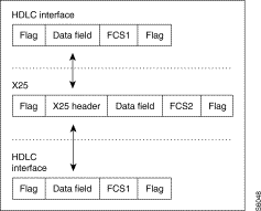
Each HDLC or Frame-Relay frame is passed in a complete sequence of X.25 data packets with the M bit set if the frame is split into several packets. Figure 4-1 illustrates this principle for a HDLC frame.
In case of a frame relay interface, the two-bytes header is not transmitted over X25 as shown in the Figure 4-2. Congestion indication is managed locally. For more details about congestion mechanism refer to the congestion mechanism part.
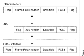 Frame Relay Interface
With encapsulation type such as CC, DC, FC there is the possibility to define which layer 3 is used within a frame. This is the difference with the other ones which are transparentness paragraph 1.1).
When a layer 3 is defined, this one is suppressed from the data field towards X.25.
0x800 is the Ethertype value for IP. RFC 894 specifies a list of different values available. By example 0x806 identifies ARP.
RFC 1356 specifies how must be encapsulated protocols over X.25. There are several possibilities, as such direct encapsulation, null encapsulation...
In direct encapsulation a protocol is identified by a Network Layer Protocol ID (NLPID). For IP the value of the NLPID is CC.
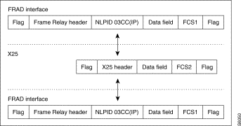
RFC 1490 defines the way to encapsulate any protocol over Frame-Relay. IP in routing mode is encapsulated within an Unnumbered I frame, Control field's value is 03, and behind the NLPID is CC. So for IP over Fame-Relay there are 2 bytes (03CC) behind the DLCI.
Both additional bytes, following the frame relay header and defining a particular network layer protocol encapsulated over Frame Layered IP), may be removed before forwarding the frame over X25 as illustrated in Figure 4-3.
As explained already previously, this encapsulation type allows, with the regroupment option, to forward several HDLC, Frame-Relay frames or LAN datagrams within one X.25 packet.
For that an additional separator field precedes each frame inserted in the data field of the x.25 packet.
This separator uses 2 bytes and its layout is as followed:

This separator, so-called SEP, is also used, in case of Frame-Relay connections, for carrying from end to end the congestion indication. The FastPad copies the congestion bits received from the incoming Frame-Relay frame within the SEP field. The remote devices FastPad one) will deliver a Frame-Relay frame by setting the congestion bit value according to what has been received from the X.25 network in the SEP field.
Figure 4-5 represents a Frame-Relay connection using the Multi-frame (MFR) type with regroupment.
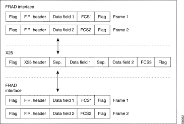
The number of frames encapsulated in one single X.25 packet depends on the HDLC, or Frame-relay frame size and the maximum packet size allowed over X.25 during the negotiation phase.
Multi-frame with regroupment must be accepted during the call set-up phase.
To have several frames in one single X.25 packet, the number of frames queued must be higher than configurable thresholds (see congestion mechanism part).
The encapsulation type is defined for a logical connection. It means that somewhere it is necessary to make a link with a X.121 address. In this kind of configuration there is always a calling and called site.
This is done in Class 8 Rec0, Rec1, Rec4, Rec5.
Table 4-2 and Figure 4-6 illustrate it. Only the encapsulation configuration is represented.
LMP1 | LMP2 |
CLASS 8 REC 0
| |
0 90002007 | 0 90001007 |
CLASS 8 REC 1
| |
0 01,80 FAST SELECT | 0 01,80 |
CLASS 8 REC 4
| |
0 1 SLOW CALL TIME-OUT | 0 0 |
CLASS 8 REC 5
| |
0 FC,08,00 | 0 FC,08,00 |
 Encapsulation Type Defined for a Logical Connection
In that case, a layer 3 is specified. 0x800 identifies IP. These two bytes will be suppressed towards X.25.
To interwork with other routers, encapsulation type CC must be used.
The following examples do not represent all possible combinations but only those which can make sense to be used or represent a certain interest.
A logical connection is established between the LMP and the router over the X.25 network with the NLPID value CC in the Call user data field. The Ethertype 0x800 is suppressed towards X.25.


Encapsulation type CD is used to be transparent. FD can be used to regrouped several frames within one single X.25 packet if the packet size allows it and Fast Select is enabled.
 CD for HDLC over FRT
CD encapsulation is used. Multi-frame one (DD) is not used since there is no congestion indication to carry, FD neither since FRT provide a standard encapsulation and that is not necessary to lose processing CPU time.
 DD or FD for FRA over FRI
In that case DD or FD encapsulation type must be used for carrying the congestion indication.
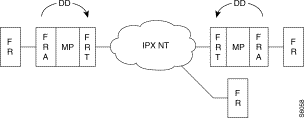
In that case DD is used to carry congestion bits from one port to another port.
If the SNMP manager is connected behind the FastPad and that the router uses LMI, a FRA stack must be set as the only one able to provide a NUI interface).
The SNMP function uses the LAN function's services which by default uses the RFC 1356.
It means it is necessary to make a translation between RFC 1356 and RFC 1490, as illustrated in Figure 4-12.

The configuration will be as illustrated in Table 4-3.
FRA | SNMP AGENT |
CLASS 8 REC 0
| |
0 900000xx | 0 900000yy |
CLASS 8 REC 1
| |
0 01,80 FAST SELECT | 0 01,80 |
CLASS 8 REC 4
| |
0 1 SLOW CALL TIME-OUT | 0 0 |
CLASS 8 REC 5
| |
0 CC,03,CC | 0 CC,08,00 |
On the FRA port the PVC used for the SNMP traffic is mapped with the sub-interface your subscriber address). The FRA stack will call the SNMP agent xx, where xx can be seen like the SAP or stockier subscriber number).
The FRA stack will suppress both additional bytes (03CC), from the Frame-Relay frame received from the router, when sending data towards the agent.
The agent will suppress both bytes 0800 before sending data towards the FRA stack, which adds both bytes 03CC before sending the Frame-Relay frame towards the router.
![]()
![]()
![]()
![]()
![]()
![]()
![]()
![]()
Posted: Thu Jan 25 14:19:07 PST 2001
All contents are Copyright © 1992--2001 Cisco Systems, Inc. All rights reserved.
Important Notices and Privacy Statement.