|
|

Table Of Contents
Setting Up the Cisco Unified Application Environment
Task 1: Log into the Management Console
Task 3: Assign Media Engines to the Application Server
Configuring an Example Environment
Assumptions About the Example Environment
Setting Up an Example Deployment and Performing Configuration Tasks
Task 1: Create an H.323 Gateway Telephony Server
Task 2: Identify the H.323 Gateway in Cisco Unified CallManager
Task 3: Set Up a Route Pattern
Task 4: Install, Configure, and Test Sample Applications
Getting Started
This chapter describes how to set up the Cisco Unified Application Environment by accessing the management console, performing basic configuration tasks, and installing applications. It also describes how to configure an example deployment and how to plan for redundancy and load balancing.
This chapter includes these topics:
•
Setting Up the Cisco Unified Application Environment
•
Before You Begin
Before you begin setting up the Cisco Unified Application Environment, you must do the following:
1.
2.
Note
Setting Up the Cisco Unified Application Environment
To set up the Cisco Unified Application Environment, you must first perform these installation and configuration tasks:
Task 1: Log into the Management Console
Task 3: Assign Media Engines to the Application Server
Task 1: Log into the Management Console
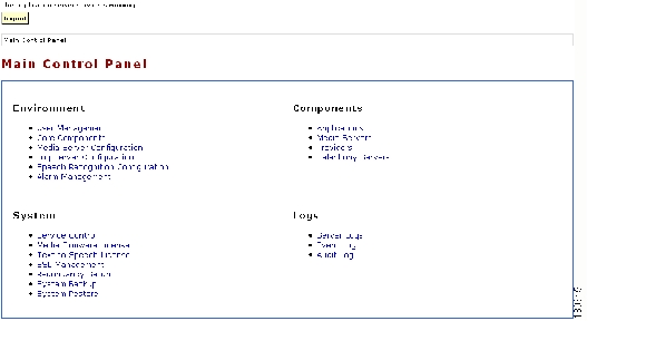
In this task, you must log into the management console to access the Main Control Panel, which you will use to perform various tasks related to the environment, system, components, and logs.
Figure 2-1 shows the Main Control Panel.
Figure 2-1 Main Control Panel
To log into the management console, follow these steps:
Procedure
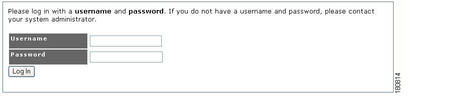
Step 1
Step 2
•
•
The Main Control Panel opens ( Figure 2-1).
Figure 2-2 Management Console Login Screen
Note
Now that you are logged into the management console, you can perform the required set-up tasks from the console.
Related Topics
•
•
Task 2: Enter License Keys
In this task, you use the management console to upload license files for media firmware and text-to-speech applications. Each license file contains a key that is required to activate a feature. Applications that use media capabilities require a media firmware license, and applications that use text-to-speech capabilities require a text-to-speech license.
To upload and activate a media firmware license, follow these steps:
Procedure
Step 1
Step 2
Step 3
Step 4
The media server is shut down and restarted.
To upload and activate a text-to-speech license, follow these steps:
Procedure
Step 1
Step 2
Step 3
Step 4
Related Topics
•
•
•
Task 3: Assign Media Engines to the Application Server
In this task, it is assumed that the Cisco Unified Application Server will be hosting applications that use media capabilities. Therefore, you must identify the Cisco Unified Application Environment servers that have media engine software activated. When this is completed, you can add the media engines to collections of media engines (media resource groups) and configure an application and associate each partition of the application with a media resource group. This enables the application server to automatically use the available media engines and apply load balancing as needed.
Note
To assign media engines to an application server, follow these steps:
Procedure
Step 1
Step 2
Step 3
Step 4
Step 5
Step 6
Note
Step 7
Step 8
Related Topics
Task 4: Configure Cisco Unified CallManager Clusters to Integrate with the Cisco Unified Application Server
In this task, it is assumed that you plan to use applications that perform telephony operations. Therefore, you must configure one or more telephony servers to serve as endpoints for making and receiving calls to and from the application server.
However, the specific configuration steps are dependent upon the specific telephony protocol that the application uses. The Cisco Unified Application Environment supports the following telephony protocols:
•
•
•
•
See the "Telephony Servers" section for instructions on configuring IP telephony servers for each protocol.
Related Topics
•
Task 5: Install Applications
In this task, you must install the sample MakeCall and AnswerCall applications that were developed using the Cisco Unified Application Designer.
Note
To install the sample MakeCall or AnswerCall application, follow these steps:
Procedure
Step 1
Step 2
Step 3
Step 4
Step 5
The file is uploaded and added to the list on the Applications page.
After completing tasks 1-5, you are now ready to use the Cisco Unified Application Environment to create, deploy, and execute converged voice and data applications. The specific procedures for these tasks differ according to your network infrastructure and application type. The next section, Configuring an Example Environment, describes how to configure Cisco Unified Application Environment to support two sample applications, load the applications, and then execute them.
Related Topics
•
Configuring an Example Environment
This section provides an example deployment scenario for setting up and configuring a Cisco Unified Application Environment. The specific tasks required for setting up the Cisco Unified Application Environment will vary depending on the integration requirements of each application.
Assumptions About the Example Environment
The required tasks for setting up the Cisco Unified Application Environment will vary according to specific protocols and applications such as these:
•
•
•
•
To show how the set-up process is typically performed, this section describes how to set up and configure an example environment having these properties:
•
•
•
•
–
–
•
–
–
•
Setting Up an Example Deployment and Performing Configuration Tasks
To set up your example deployment, you must perform these configuration tasks:
Note
•
•
•
•
Task 1: Create an H.323 Gateway Telephony Server
In this task, you will use H.323 as the IP telephony protocol by first creating a single H.323 gateway telephony server corresponding to the subscriber IP address of the Cisco Unified CallManager cluster. You will place the gateway into an H.323 call route group (a collection of H.323 gateways). When you later configure an application, you can associate a call route group with each application partition.
To create the H.323 gateway telephony server, follow these steps:
Procedure
Step 1
Step 2
Step 3
Step 4
Step 5
Step 6
Step 7
Related Topics
•
Task 2: Identify the H.323 Gateway in Cisco Unified CallManager
In this task, you must define an H.323 gateway using the Cisco Unified CallManager administrative interface. You must also verify that the H.323 gateway device name corresponds to the IP address or Domain Name Service (DNS) name of the primary IP address of the Cisco Unified Application Server.
To associate the H.323 gateway and identify the correct parameters, follow these steps:
Procedure
Step 1
Step 2
Step 3
Step 4
Step 5
Step 6
Step 7
Related Topics
Task 3: Set Up a Route Pattern
Task 3: Set Up a Route Pattern
In this task, you must set up a route pattern in Cisco Unified CallManager to provide a route to the H.323 gateway that you defined in Task 2.
To set up a route pattern in Cisco Unified CallManager, follow these steps:
Procedure
Step 1
Step 2
Step 3
Step 4
Step 5
Step 6
You are now ready to install, configure, and test sample applications.
Related Topics
Task 4: Install, Configure, and Test Sample Applications
Task 4: Install, Configure, and Test Sample Applications
After completing tasks 1-3, you can install, configure, and test these sample applications:
•
•
In this task, you will:
1.
2.
3.
4.
5.
6.
7.
MakeCall Application
The MakeCall application tests outbound dialing from the Cisco Unified Application Server to Cisco Unified CallManager as follows:
1.
2.
3.
A successful outbound call indicates that the Cisco Unified CallManager cluster interprets the call as originating from the H.323 gateway that represents the Cisco Unified Application Server.
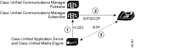
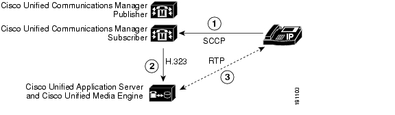
Figure 2-3 shows the call flow in which the MakeCall application makes a call to an internal IP phone.
1.
2.
3.
Figure 2-3 MakeCall Application IP Phone Call Flow
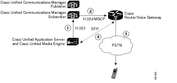
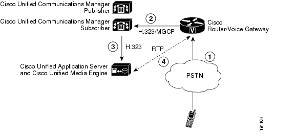
Figure 2-4 shows the call flow in which the MakeCall application makes a call to a phone on the Public Switched Telephone Network (PSTN).
1.
2.
3.
4.
Figure 2-4 MakeCall Application PSTN Call Flow
To install the MakeCall application, follow these steps:
Procedure
Step 1
Step 2
Step 3
Step 4
Step 5
The file is uploaded and added to the list on the Applications page.
Step 6
Step 7
Note
The MakeCall application incorporates the HandleMakeCall script, which triggers, or initiates, when an HTTP request is received over port 8000 on the application server. Because multiple HTTP-triggered scripts can be installed on the application server, you must verify that the HandleMakeCall script uses a unique trigger parameter.
To verify the trigger parameters for the HandleMakeCall script, follow these steps:
Procedure
Step 1
Step 2
Step 3
Step 4
Step 5
Step 6
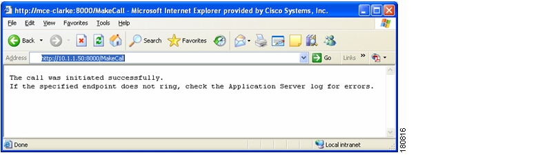
After installing the MakeCall application and verifying the trigger setting, you can test the application by opening a web browser and entering http://<Application Server IP>:8000/MakeCall.
If the outbound call succeeds, a message is presented, as shown in Figure 2-5, and you hear `goodbye' three times, then you have successfully integrated outbound calling using H.323 and the Cisco Unified Application Environment.
Figure 2-5 Testing the MakeCall Application
Note
AnswerCall Application
The AnswerCall application tests inbound calling to the Cisco Unified Application Server as follows:
1.
2.
3.
A successful call indicates that the Cisco Unified Application Server is able to receive incoming calls.
Figure 2-6 shows the call flow in which the AnswerCall application answers a call from an internal IP phone.
1.
2.
3.
Figure 2-6 AnswerCall Application IP Phone Call Flow
Figure 2-7 shows the call flow in which the AnswerCall application answers a call from the PSTN.
1.
2.
3.
4.
Figure 2-7 AnswerCall Application PSTN Call Flow
To install the AnswerCall application, follow these steps:
Procedure
Step 1
Step 2
Step 3
Step 4
Step 5
The file is uploaded and added to the list on the Applications page.
Step 6
Step 7
Note
The HandleInboundCall script, which handles calls routed to the application server, does not contain any pre-defined trigger parameters. However, because it is a dial-in application (you dial a number to test it), it is a good idea to define a trigger parameter for the script.
For consistency with the route pattern 5000X, which was defined in Task 3: Set Up a Route Pattern, define a trigger parameter with the name `to' and value `50000.'
To define the trigger parameter for the HandleInboundCall script, follow these steps:
Procedure
Step 1
Step 2
Step 3
Step 4
Step 5
Step 6
To test the application, call 50000 from an IP phone that is configured to dial to the previously-defined route pattern ( Figure 2-8). The call should answer immediately, and you should hear three 'goodbye's followed by a hang up.
Note
Figure 2-8 Testing the AnswerCall Application
You have now completed the installation, configuration, and testing of two sample applications. See these chapters for additional configuration and maintenance information and instructions:
•
•
•
Planning for Redundancy
The Cisco Unified Application Environment includes limited support for redundancy with clustering:
•
•
After the master/standby relationship is configured, the standby machines create an active replication link with the respective master servers. If a master server becomes unreachable, its standby uses the replicated configuration information to register the devices held by the master server in addition to its own.
When the master server recovers, the standby relinquishes the devices that were originally owned by the master and then signals the master to begin registration. The master registers its original devices and the configuration is restored.
The support for redundancy (with clustering) is subject to these limitations:
•
•
![]()
![]()
![]()
![]()
![]()
![]()
![]()
![]()
Posted: Tue Oct 17 11:01:30 PDT 2006
All contents are Copyright © 1992--2006 Cisco Systems, Inc. All rights reserved.
Important Notices and Privacy Statement.