|
|

Table Of Contents
Configuring the Cisco Unified Application Server
Configuring Environment Parameters
Configuring the Cisco Unified Application Server
This chapter describes how to use the Cisco Unified Application Environment management console to manage application servers and includes these sections:
•
Configuring System Parameters
•
Configuring Components
The management console provides access to the system components used to manage IP telephony
applications. The Components group contains links to these configuration pages:
•
•
•
•
•
Applications
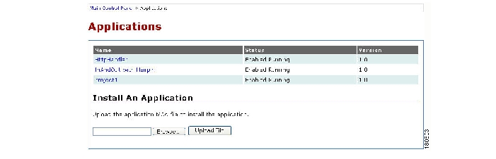
You must open the Applications page ( Figure 3-1) to install and uninstall applications. When you open the Applications page, the page displays the application name (displayed as a link), status, and version number. An application typically includes configuration items that are unique to your deployment and which you must configure after the application is installed.
This section describes how to install, enable, disable, modify, and uninstall applications.
Note
Figure 3-1 Applications Page
To install an application, follow these steps:
Procedure
Step 1
Step 2
Step 3
Step 4
The Application Manager processes the file, installs the application, and updates the Applications page to list the application.
To enable an application, follow these steps:
Procedure
Step 1
Step 2
Step 3
The application begins running. If you return to the Applications page, the Status column shows that the application is enabled.
To disable an application, follow these steps:
Procedure
Step 1
Step 2
Step 3
The application stops running. If you return to the Applications page, the Status column shows that the application is Disabled.
To modify application settings, follow these steps:
Procedure
Step 1
Step 2
Step 3
Step 4
To uninstall an application setting, follow these steps:
Procedure
Step 1
Step 2
Step 3
Step 4
Step 5
The application is removed.
Partitions
All application configuration occurs at the partition level. A partition is a configuration profile for an application. Applications can support multiple partitions, enabling you to create and execute multiple versions of the same application on a single Cisco Unified Application server.
Partitions are flexible and can be useful in a variety of situations. For example, if an application is intended to serve end-users located on distinct Cisco Unified CallManager clusters, it is often desirable for all call control and media streams to terminate to the network and telephony resources contained within each cluster. At the same time, it may be desirable to have another configurable protocol on the application, such as LDAP, which makes reference to the same central location, regardless of the partition.
Each partition is associated with a call route group and media resource group. By defining unique call route groups and media resource groups, you can identify the partitions that use individual media servers. For each partition, you can also determine which Cisco Unified CallManager cluster is used for making calls by specifying a call route group that corresponds to the particular telephony protocol and group.
Each application is also associated with scripts, which are partitioned along with the application. Because multiple scripts can execute actions through the same protocol, you must specify the conditions under which a partitioned script should initiate action.
For example, assume that an application has one script and three partitions and activates on an IncomingCall trigger. The default partition has no triggering parameters and can act as a catch-all for events which do not match other partitions.
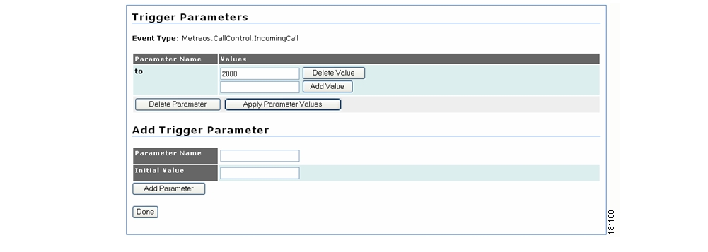
The application server determines the best match handler for a given event. Other partitions take effect if their trigger parameters are activated. For example, if Partition 2 specifies to=2000, then when a call comes in for extension 2000, partition 2 will activate. If no trigger matches, the default partition will be active.
A partition is similar to a configuration template for a script and follows these rules:
•
•
•
•
To create a new partition, follow these steps:
Procedure
Step 1
Step 2
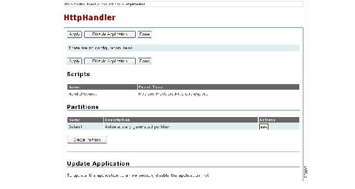
A page opens to display available settings ( Figure 3-2).
Figure 3-2 Application Manager Example Page
Step 3
Step 4
Step 5
Note
Step 6
Step 7
Step 8
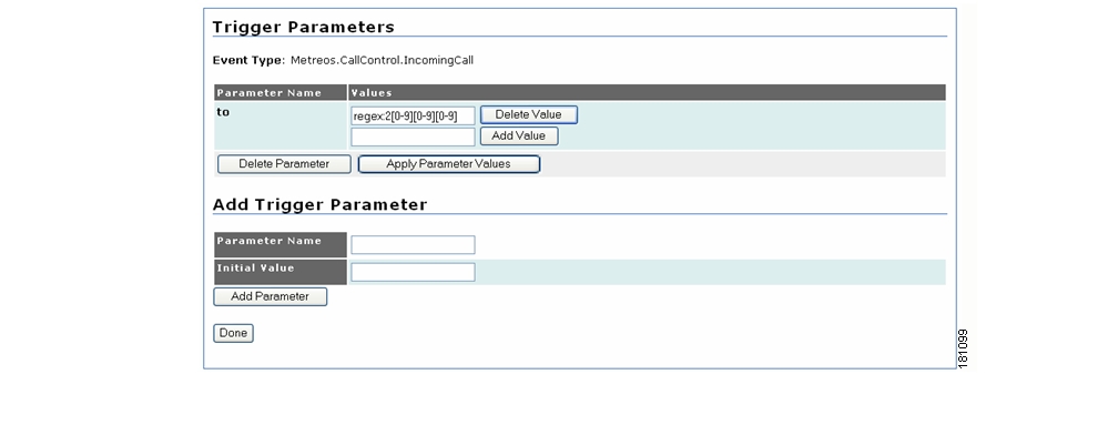
Defining Trigger Parameters
You can define triggers in any of the following ways:
•
•
•
•
Note
Figure 3-3 Example Single Value Trigger Parameter Configuration
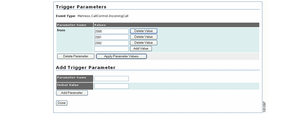
Figure 3-4 Example Value List Trigger Parameter Configuration
Figure 3-5 Example Single Regular Expression Trigger Parameter Configuration
Figure 3-6 Example Combined Trigger Parameter Configuration
Event Types and Trigger Parameters
This section lists trigger parameters for the following event types:
•
•
•
•
•
Media Server Engines
In order for the Cisco Unified Application Environment to act as a media endpoint, a Cisco Unified Media Engine must be present and the Cisco Unified Application Environment must be configured to use the server. The decision to use a media engine ultimately rests with the needs of the application. Applications that place or answer calls typically require a media engine.
Note
To be available for use by applications, each media engine must be placed in a media resource group, which is assigned within the application partition. All media engines are placed automatically into the Default media resource group, and all application partitions can use the default group. Creating custom media resource groups is recommended in the following cases:
•
•
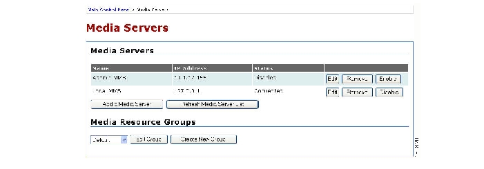
Use the Media Servers page ( Figure 3-7) to create and configure media servers and media resource groups. A media resource group is a container for a collection of media servers. Each media server must be associated with one or more groups. It is also possible, but not necessary, to create media resource groups. The system provides a default media resource group for use if multiple groups are not needed.
Figure 3-7 Media Servers Page
To create and configure media servers, follow these steps:
Procedure
Step 1
Step 2
•
Click Add a Media Server, enter values as described in Table 3-7, and click Add.
•
Click the Edit button to the right of the server entry, enter values as described in Table 3-7, and click Apply.
•
Click the Enable button to the right of the server entry.
•
Click the Enable button to the right of the server entry.
To add a media resource group, follow these steps:
Procedure
Step 1
Step 2
Step 3
Step 4
•
•
Step 5
To edit an existing media resource group, follow these steps:
Procedure
Step 1
Step 2
Step 3
Step 4
•
•
Step 5
The system adds the server and displays it in the Media Servers list.
Step 6
To remove a media server from the group without removing it from the system, follow these steps:
Procedure
Step 1
Step 2
Step 3
Step 4
The group is deleted and removed from the pull-down list on the Media Servers page.
Caution
To remove a media server from the system, follow these steps:
Procedure
Step 1
Step 2
The media server is deleted and removed from the list on Media Servers page.
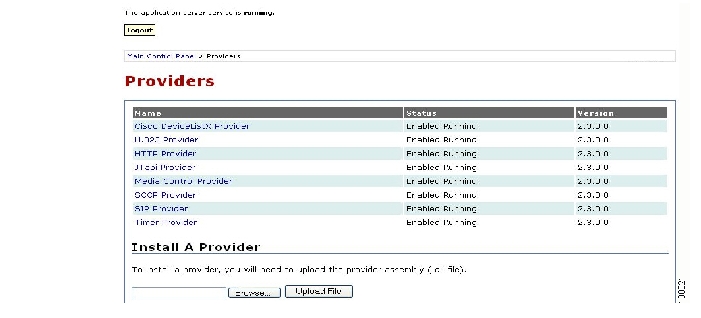
Providers
Providers are application server plug-in modules that open network ports and allow the runtime environment to communicate with devices on the network. Use the Providers page ( Figure 3-8) to display the list of providers shipped with the Cisco Unified Application Server, the status of each provider (Enabled, Running, or Disabled), and the version number. Clicking on the provider name launches the configuration page for that provider.
Figure 3-8 Providers Page
From the Main Control Panel, click Providers to display the list of providers.
Each provider configuration page includes following sections:
•
•
To invoke the extension, click Invoke Extension.
Note
Click an underlined link to select one of the following providers:
To modify provider settings, make changes as needed, and click Update. Click Done to return to the Providers page.
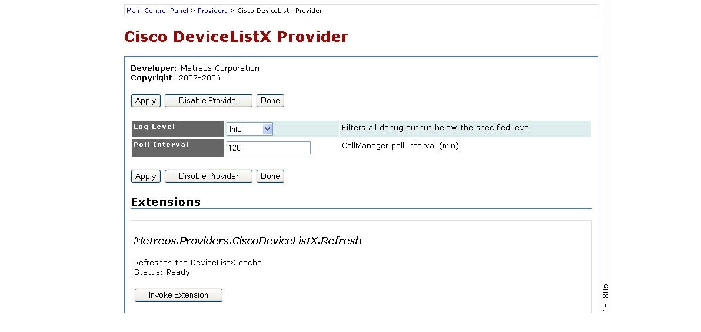
CiscoDeviceListX Provider
The CiscoDeviceListX provider communicates with Cisco Unified CallManager to retrieve and cache real-time device information for application use. The CiscoDeviceListX (3.X, 4.X) and SNMP (5.X) protocols are used to gather this information. The Cisco Unified CallManagers with which the Cisco Unified Application Server communicates are specified in the Telephony Servers pages.
The CiscoDeviceListX provider supports the following extensions, which you can invoke on the CiscoDeviceListX Provider page:
•
Figure 3-9 shows the Cisco DeviceListX Provider page, and Table 3-8 lists the provider parameters.
Figure 3-9 Cisco DeviceListX Provider Page
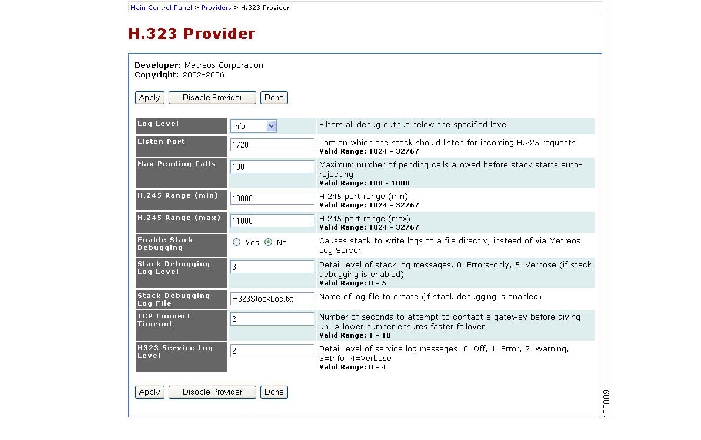
H.323 Provider
The H.323 provider uses the H.323 protocol to create, receive, and control IP telephony calls between Cisco Unified CallManager nodes. The H.323 provider has an H.323 gateway device appearance in Cisco Unified CallManager.
Figure 3-10 shows the H.323 Provider page, and Table 3-9 lists the provider parameters.
Figure 3-10 H.323 Provider Page
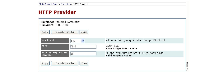
HTTP Provider
The HTTP provider receives HTTP requests over port 8000. These requests are then routed to the appropriate application for processing.
Figure 3-11 shows the HTTP Provider page, and Table 3-10 lists the provider parameters.
Figure 3-11 HTTP Provider Page
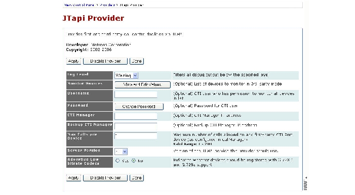
JTAPI Provider
The JTAPI provider uses the CTI protocol to create, receive, and control IP telephony calls. The JTAPI provider registers as a CTI route point and CTI port in Cisco Unified CallManager and can use JTAPI to monitor phone devices.
Figure 3-12 shows the JTapi Provider page, and Table 3-11 lists the provider parameters.
Figure 3-12 JTapi Provider Page
Perform these actions on the JTapi Provider page:
•
•
•
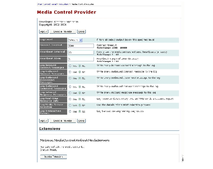
Media Control Provider
The Media Control provider manages media engines to provide media capabilities to applications. The Media Control provider supports the following extensions, which you should invoke only under the direction of a Cisco technical support engineer:
•
•
•
•
Figure 3-13 shows an excerpt of the Media Control Provider page, and Table 3-12 lists the provider parameters.
Figure 3-13 Media Control Provider Page
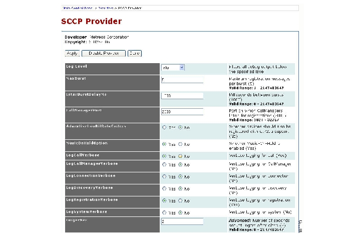
SCCP Provider
The SCCP provider uses the SCCP protocol to create, receive, and control IP telephony calls. The SCCP provider registers as an SCCP 7960 device in Cisco Unified CallManager.
Figure 3-14 shows an excerpt of the SCCP Provider page. Table 3-13 lists the basic SCCP parameters; the screen also includes an extensive set of advanced parameters, which should not require modification.
Figure 3-14 SCCP Provider Page
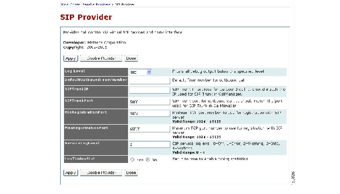
SIP Provider
The SIP provider uses the SIP protocol to create, receive, and control IP telephony calls between Cisco Unified CallManager nodes. The SIP provider either behaves as a SIP trunk or registers as SIP 7961G-GE devices in Cisco Unified CallManager.
Figure 3-15 shows the SIP Provider page, and Table 3-14 lists the provider parameters.
Figure 3-15 SIP Provider Page
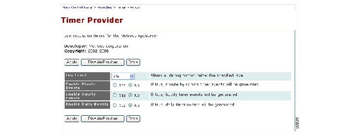
Timer Provider
The Timer provider makes timers available for use by applications. It does not communicate with any other system.
Click the Timer provider link to configure the Timer provider. Figure 3-16 shows the Timer Provider page, and Table 3-15 lists the provider parameters.
Figure 3-16 Timer Provider Page
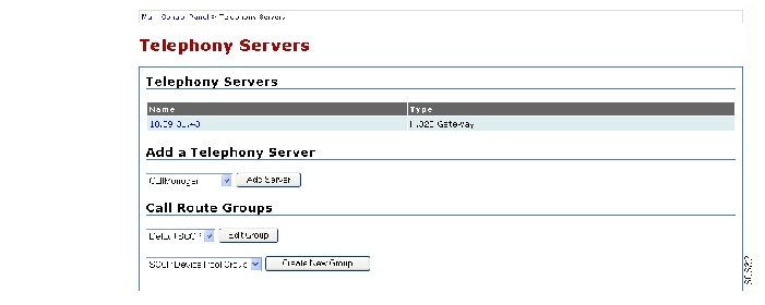
Telephony Servers
Every IP telephony system must contain at least one telephony server. The management console provides a telephony server configuration page for adding and configuring telephony servers and devices on those servers. When adding a telephony server, however, its devices must be associated with one or more call route groups.
Just as a media server group functions as a container for media servers, a call route group functions as a container for telephony devices. Each telephony device must belong to one or more call route groups.
Note
From the main Main Control Panel, click Telephony Servers to open the Telephony Servers page ( Figure 3-17).
Figure 3-17 Telephony Servers Page
The application server currently supports these call control protocols:
•
•
•
•
It also supports these types of telephony servers:
•
•
•
•
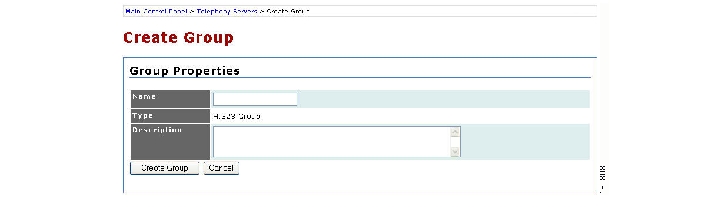
Creating H.323 Call Route Groups and Gateways
This section describes how to create and configure H.323 call route groups and gateways. If a call route group other than the default is required, you can create a new H.323 call route group using this procedure.
To add a new call route group, follow these steps:
Procedure
Step 1
Step 2
Step 3
Figure 3-18 Configuring a New H.323 Telephony Group
Step 4
Step 5
Step 6
Step 7
Before you can add an H.323 telephony server to a group, you must create an H.323 gateway. Because H.323 does not require static configuration of devices, the gateway is added to a call route group. All logical devices created during runtime will automatically be part of that same group.
To create an H.323 gateway, follow these steps:
Procedure
Step 1
Step 2
Step 3
Step 4
Step 5
Creating CTI Telephony Devices
Computer Telephony Integration (CTI), unlike H.323, is an IP telephony protocol based on line-oriented telephony devices. This section describes how to set up and administer CTI ports and route points that are configured on a CTI Manager. These properties apply to CTI devices:
•
•
•
•
•
These procedures describe how to create:
•
•
–
–
To create a CTI route group, follow these steps:
Procedure
Step 1
Step 2
Step 3
Step 4
Step 5
Step 6
Step 7
Cisco Unified CTI clusters are known as Cisco Unified CallManager clusters. You can create a Cisco Unified CallManager cluster and associate it with the new group.
To add a Cisco Unified CallManager cluster, follow these steps:
Procedure
Step 1
Step 2
Step 3
Step 4
Step 5
To create a CTI manager, follow these steps:
Procedure
Step 1
Step 2
Step 3
Step 4
Step 5
You can now create devices.
To create a CTI device pool, follow these steps:
Procedure
Step 1
Step 2
Step 3
Step 4
To create a CTI route point, follow these steps:
Procedure
Step 1
Step 2
Step 3
Step 4
Click any of the View or Edit buttons associated with the devices to view or edit them.
Configuring SCCP Devices
For applications that require the use of SCCP devices, there must be at least one SCCP device pool configured to contain SCCP devices.
To add a subscriber to Cisco Unified CallManager, follow these steps:
Procedure
Step 1
Step 2
Step 3
Step 4
Step 5
Step 6
To create a device pool on the subscriber created to contain SCCP devices, follow these steps:
Procedure
Step 1
Step 2
Step 3
Step 4
Step 5
Configuring System Parameters
The System group contains links to these Cisco Unified Application Environment configuration pages:
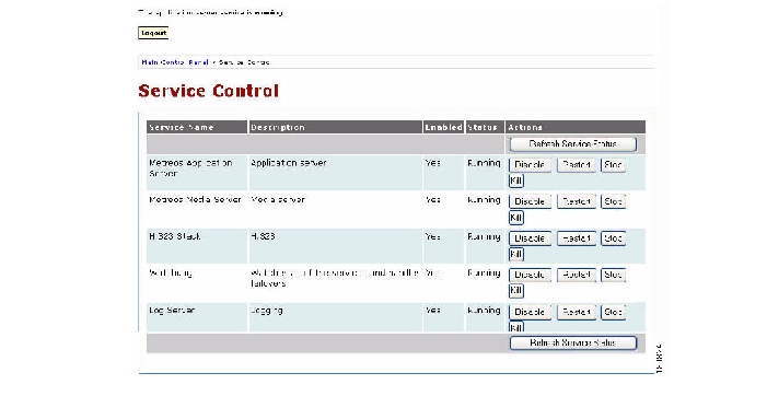
Service Control
The Service Control page is used to enable, disable, stop, restart, or kill services that run on the application server. Under normal circumstances, it should not be necessary to perform these functions; these functions are required only in these instances:
•
•
•
Note
From the Main Control Panel, open the Service Control page ( Figure 3-19) to show the services that are currently running and to enable, disable, start, restart, or stop the services.
Figure 3-19 Service Control Page
The following information is presented for each service:
•
•
•
•
–
–
–
–
–
•
–
–
–
–
–
–
An enabled service automatically starts when the system is rebooted; a disabled service does not. When a service is disabled, the system automatically stops it.
To perform an action on a service, click the desired button to the right of the action.
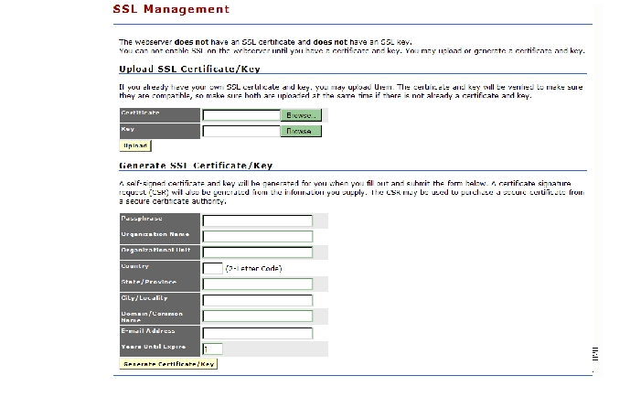
SSL Management
The management console web server does not have an SSL certificate or SSL key. If you need to use HTTPS (HTTP-over-SSL) instead of HTTP for management console access, then you must supply a security certificate and key. Open the SSL Management page ( Figure 3-20) to manage SSL certificates and keys.
If you already have your own SSL certificate and key, they are verified upon upload to make sure that they are compatible. Make sure you upload them at the same time.
Figure 3-20 SSL Management Page
To upload an SSL certificate and key, follow these steps:
Procedure
Step 1
Step 2
Step 3
Step 4
To generate a new SSL certificate and key, follow these steps:
Procedure
Step 1
Step 2
Step 3
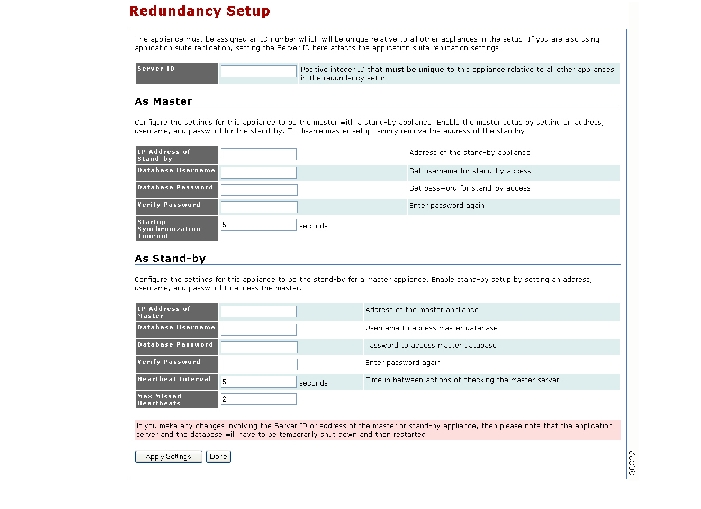
Redundancy Setup
The Cisco Unified Application Environment supports redundant configurations for certain protocols, including Session Initiation Protocol (SIP), Skinny Client Control Protocol (SCCP), and computer telephony integration (CTI). You can configure a master and stand-by application server. The stand-by server attempts to contact the master server every few seconds. If the specified number of attempts fails, the stand-by server takes over.
Use the Redundancy Setup page ( Figure 3-21) to assign a unique ID number for each of the application servers and to configure the master and stand-by servers.
Figure 3-21 Redundancy Setup
Page
To set up redundant operations, follow these steps:
Procedure
Step 1
Step 2
Step 3
Step 4
Step 5
Step 6
Note
Configuring Environment Parameters
The Environment group contains links to the following Cisco Unified Application Environment configuration pages:
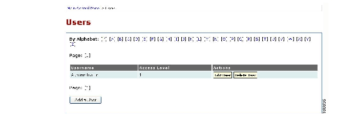
User Management
A user account is required for each user who will access the system. By creating a different account for each user, you can ensure that audit logs will accurately record each user's interactions with the system. From the Main Control Panel, open the Users page ( Figure 3-22) to add users and to list existing users and their access levels.
Figure 3-22 Users Page
To add a user, follow these steps:
Procedure
Step 1
Step 2
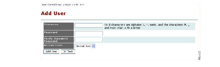
The Add User page opens.
Note
Figure 3-23 Add User Page
Step 3
Step 4
Step 5
•
•
•
•
•
Step 6
Step 7
To change a user password, follow these steps:
Procedure
Step 1
Step 2
Step 3
The Edit User page opens.
Step 4
Step 5
Step 6
To remove a user, follow these steps:
Procedure
Step 1
Step 2
Step 3
Step 4
The user record is deleted.
Step 5
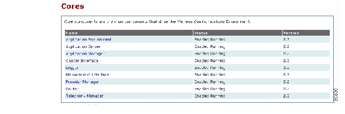
Configuring Core Components
From the Main Control Panel, open the Cores page ( Figure 3-24) to configure Cisco Unified Application Environment core components.
Figure 3-24 Cores Page
To configure core components, follow these steps:
Procedure
Step 1
Step 2
Step 3
•
•
•
•
•
•
•
•
•
Step 4
Step 5
You can also invoke extensions from some of the core components pages that provide additional services.
Table 3-25 Application Server Parameters
Log Level
Type and amount of information the system writes to the log for each component
Server Name
Identifier for application server
Table 3-27 Cluster Interface Parameters
Log Level
Type and amount of information the system writes to the log for each component
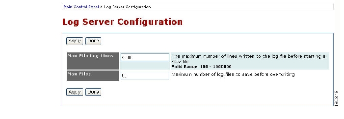
Log Server
From the Main Control Panel, open the Log Server Configuration page ( Figure 3-25) to specify the maximum size and number of log files.
Figure 3-25 Log Server Configuration Page
To configure the log server, follow these steps:
Procedure
Step 1
Step 2
Step 3
Step 4
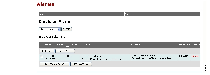
Alarm Management
Real-time alarm messages warn of critical system events, such as a server failing to start. Use the Alarms page to define which SMTP or SNMP manager receives the alarm messages.
From the Main Control Panel, open the Alarms page ( Figure 3-26) to list current alarms and specify the destinations to receive alarm messages.
Figure 3-26 Alarms Page
To add new alarm destinations, follow these steps:
Procedure
Step 1
Step 2
Step 3
•
•
![]()
![]()
![]()
![]()
![]()
![]()
![]()
![]()
Posted: Tue Oct 24 07:59:13 PDT 2006
All contents are Copyright © 1992--2006 Cisco Systems, Inc. All rights reserved.
Important Notices and Privacy Statement.