|
|

Table Of Contents
Cisco Systems Equipment Needed
Configuring the Lucent/Avaya Definity G3si PBX
Calling Name and Number Feature
Lucent/Avaya Definity G3si Software Release
Catalyst 6000 Switch Configuration
youApplication Note
Lucent/Avaya Definity G3si V9 PBX with CallManager using the Cisco 6608-E1 PRI EURO Gateway
This application note discusses the integration of the Lucent/Avaya Definity G3si V9 PBX with CallManager using the Cisco 6608-T1 PRI EURO Gateway.
Integration Description
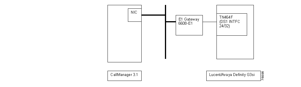
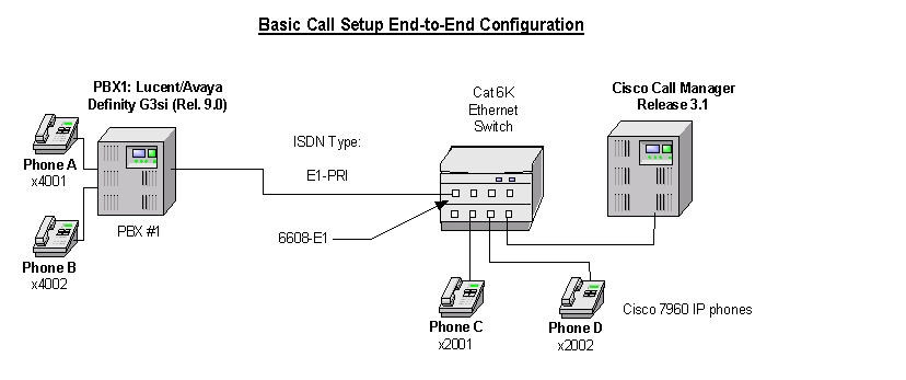
Connectivity is achieved by using the ETSI standard PRI protocol. The Lucent/Avaya Definity G3si can be configured as either the NETWORK or USER side. The figure below shows the general network layout for the integration.
Network Layout
Cisco Systems Equipment Needed
•
Hardware (Gateway): Cisco 6608 E1 Port
•
PBX Requirements
•
•
Features
Key features supported:
•
•
Key features not supported:
•
•
Configuring the Lucent/Avaya Definity G3si PBX
To configure the Lucent/Avaya Definity G3si PBX, do the following:
Step 1.
Step 2.
Step 3.
Step 4.
Circuit Pack
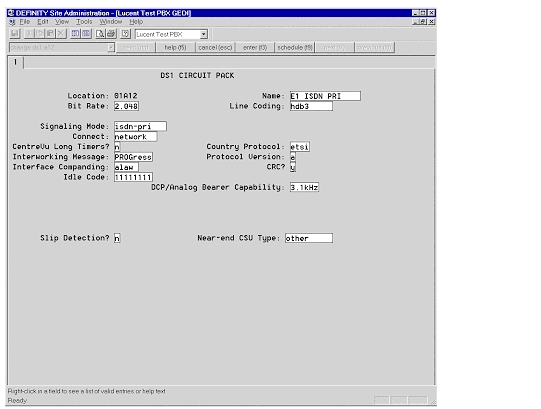
The following figures show the configuration of the DS1 circuit pack.
DS1 Circuit Pack
Signaling Group
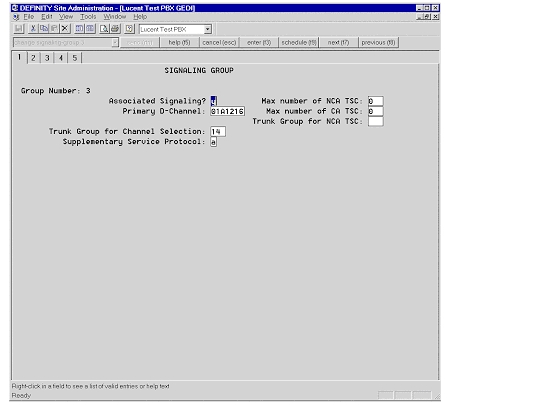
The following figure shows the configuration of the signaling group.
Signaling Group
Trunk Group
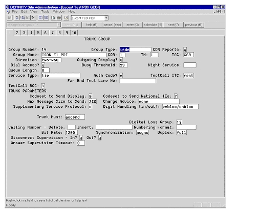
The following figures show the configuration of the trunk group.
Trunk Group
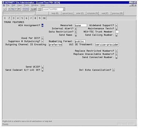
Trunk Group—Trunk Features
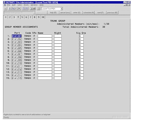
Trunk Group—Group Member Assignments
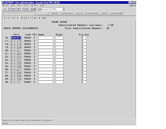
Trunk Group—Group Member Assignments Continued
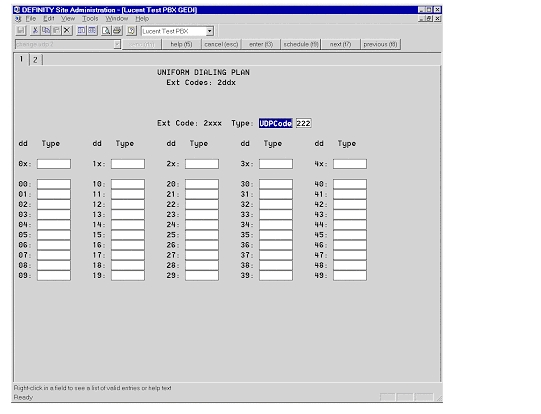
Uniform Dialing Plan
The following figures show the configuration of the uniform dialing plan.
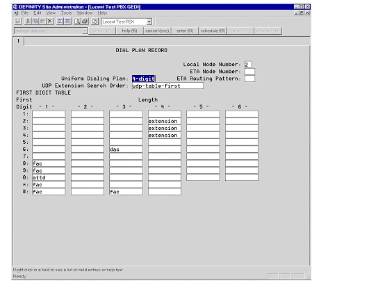
Dial Plan Record
Uniform Dialing Plan
Configuring Cisco CallManager
To configure Cisco CallManager, do the following:
Step 1.
Step 2.
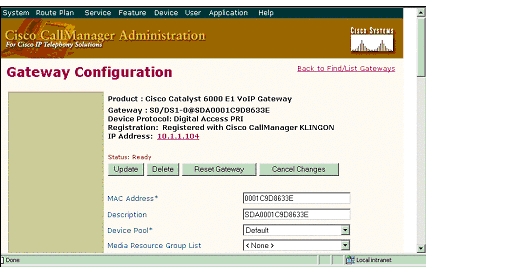
Gateway Configuration
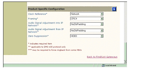
The following figures show the configuration of the Cisco 6608 Gateway.
Cisco 6608 Gateway Configuration
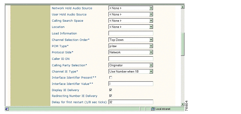
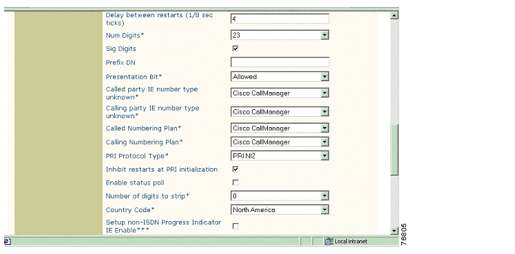
Cisco 6608 Gateway Configuration Continued
Cisco 6608 Gateway Configuration Continued
Cisco 6608 Gateway Configuration Continued
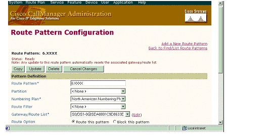
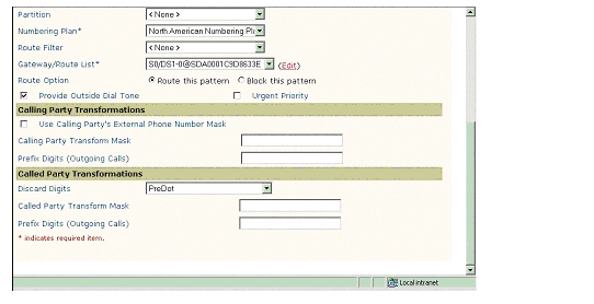
Route Pattern Configuration
The following figures show the configuration of the route pattern.
Route Pattern Configuration
Route Pattern Configuration Continued
Considerations
Calling Name and Number Feature
When calling from a Cisco 7960 IP phone to a Lucent/Avaya digital phone, Calling Name and Number are displayed on both phones after the call is answered. The Cisco 7960 phone, however, displays only the Called Number even though Lucent/Avaya sends both the Connected Name and Connected Number in the CONNECT message.
When calling from a Lucent/Avaya digital phone to a Cisco 7960 IP phone, the IP phone displays the Connected Name and Number after the call is answered. The Lucent/Avaya phone, however, does not display the Called Name or the Called Number. It was verified using an ISDN protocol analyzer that the CallManager was not sending the Connected Name or Connected Number information in the connect message back to PBX.
Integration Testing
This section contains information about the setup used in testing the integration of the Lucent/Avaya Definity G3si and the Cisco 6608-E1 PRI EURO Gateway.
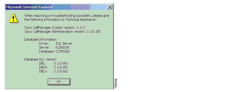
CallManager Software Release:
The following figure shows the information about the release of CallManager being used.
CallManager Software Release
Lucent/Avaya Definity G3si Software Release
The following release of the Lucent/Avaya Definity G3si was used:
•
•
Catalyst 6000 Switch Configuration
The following shows the configuration of the Catalyst 6000 Switch.
Console> (enable) show versionWS-C6006 Software, Version NmpSW: 5.5(6a)Copyright (c) 1995-2001 by Cisco SystemsNMP S/W compiled on Feb 23 2001, 10:23:18System Bootstrap Version: 5.3(1)Hardware Version: 2.0 Model: WS-C6006 Serial #: TBA04511172Mod Port Model Serial # Versions--- ---- ------------------- ----------- --------------------------------------1 2 WS-X6K-SUP1A-2GE SAD05010NBK Hw : 7.0Fw : 5.3(1)Fw1: 5.4(2)Sw : 5.5(6a)Sw1: 5.5(6a)WS-F6K-PFC SAD05020221 Hw : 1.13 48 WS-X6348-RJ-45 SAD04420N7B Hw : 1.4Fw : 5.4(2)Sw : 5.5(6a)WS-F6K-VPWR Hw : 1.04 24 WS-X6624-FXS SAD050203M8 Hw : 3.0Fw : 5.4(2)Sw : 5.5(6a)HP : A00203010010; DSP : A003E031 (3.3.32)5 8 WS-X6608-T1 SAD04400EM0 Hw : 1.1Fw : 5.4(2)Sw : 5.5(6a)HP1: D00403010017; DSP1: D005E031 (3.3.32)HP2: D00403010017; DSP2: D005E031 (3.3.32)HP3: D00403010017; DSP3: D005E031 (3.3.32)HP4: D00403010017; DSP4: D005E031 (3.3.32)HP5: D00403010017; DSP5: D005E031 (3.3.32)HP6: D00403010017; DSP6: D005E031 (3.3.32)HP7: D00403010017; DSP7: D005E031 (3.3.32)HP8: D00403010017; DSP8: D005E031 (3.3.32)6 8 WS-X6608-E1 SAD04380DW1 Hw : 1.1Fw : 5.4(2)Sw : 5.5(6a)HP1: D00403010017; DSP1: D005E031 (3.3.32)HP2: D00403010017; DSP2: D005E031 (3.3.32)HP3: D00403010017; DSP3: D005E031 (3.3.32)HP4: D00403010017; DSP4: D005E031 (3.3.32)HP5: D00403010017; DSP5: D005E031 (3.3.32)HP6: D00403010017; DSP6: D005E031 (3.3.32)HP7: D00403010017; DSP7: D005E031 (3.3.32)HP8: D00403010017; DSP8: D005E031 (3.3.32)DRAM FLASH NVRAMModule Total Used Free Total Used Free Total Used Free------ ------- ------- ------- ------- ------- ------- ----- ----- -----1 65408K 37781K 27627K 16384K 11546K 4838K 512K 198K 314KUptime is 105 days, 5 hours, 12 minutes____________________________________________________________________________________Console> (enable) show moduleMod Slot Ports Module-Type Model Sub Status--- ---- ----- ------------------------- ------------------- --- --------1 1 2 1000BaseX Supervisor WS-X6K-SUP1A-2GE yes ok3 3 48 10/100BaseTX Ethernet WS-X6348-RJ-45 yes ok4 4 24 FXS WS-X6624-FXS no ok5 5 8 T1 WS-X6608-T1 no ok6 6 8 E1 WS-X6608-E1 no okMod Module-Name Serial-Num--- ------------------- -----------1 SAD05010NBK3 SAD04420N7B4 SAD050203M85 SAD04400EM06 SAD04380DW1Mod MAC-Address(es) Hw Fw Sw--- -------------------------------------- ------ ---------- -----------------1 00-04-c0-f8-42-02 to 00-04-c0-f8-42-03 7.0 5.3(1) 5.5(6a)00-04-c0-f8-42-00 to 00-04-c0-f8-42-0100-04-9b-f0-78-00 to 00-04-9b-f0-7b-ff3 00-02-fc-20-5e-50 to 00-02-fc-20-5e-7f 1.4 5.4(2) 5.5(6a)4 00-03-32-ba-2e-35 3.0 5.4(2) 5.5(6a)5 00-01-c9-d9-3a-98 to 00-01-c9-d9-3a-9f 1.1 5.4(2) 5.5(6a)6 00-01-c9-d8-63-3e to 00-01-c9-d8-63-45 1.1 5.4(2) 5.5(6a)Mod Sub-Type Sub-Model Sub-Serial Sub-Hw--- ----------------------- ------------------- ----------- ------1 L3 Switching Engine WS-F6K-PFC SAD05020221 1.13 Inline Power Module WS-F6K-VPWR 1.0Console> (enable)______________________________________________________________________________Console> (enable) sh port 6Port Name Status Vlan Duplex Speed Type----- ------------------ ---------- ---------- ------ ----- ------------6/1 connected 1 full 2.048 E16/2 notconnect 1 full 2.048 E16/3 notconnect 1 full 2.048 E16/4 notconnect 1 full 2.048 E16/5 notconnect 1 full 2.048 E16/6 notconnect 1 full 2.048 E16/7 notconnect 1 full 2.048 E16/8 notconnect 1 full 2.048 E1Port DHCP MAC-Address IP-Address Subnet-Mask-------- ------- ----------------- --------------- ---------------6/1 enable 00-01-c9-d8-63-3e 10.1.1.104 255.255.255.06/2 enable 00-01-c9-d8-63-3f 10.1.1.118 255.255.255.06/3 enable 00-01-c9-d8-63-40 10.1.1.123 255.255.255.06/4 enable 00-01-c9-d8-63-41 10.1.1.117 255.255.255.06/5 enable 00-01-c9-d8-63-42 10.1.1.120 255.255.255.06/6 enable 00-01-c9-d8-63-43 10.1.1.121 255.255.255.06/7 enable 00-01-c9-d8-63-44 10.1.1.122 255.255.255.06/8 enable 00-01-c9-d8-63-45 10.1.1.124 255.255.255.0Port Call-Manager(s) DHCP-Server TFTP-Server Gateway-------- ----------------- --------------- --------------- ---------------6/1 10.1.1.2 10.1.1.2 10.1.1.2 10.1.1.76/2 10.1.1.2 10.1.1.2 10.1.1.2 10.1.1.76/3 10.1.1.2 10.1.1.2 10.1.1.2 10.1.1.76/4 10.1.1.2 10.1.1.2 10.1.1.2 10.1.1.76/5 10.1.1.2 10.1.1.2 10.1.1.2 10.1.1.76/6 10.1.1.2 10.1.1.2 10.1.1.2 10.1.1.76/7 10.1.1.2 10.1.1.2 10.1.1.2 10.1.1.76/8 10.1.1.2 10.1.1.2 10.1.1.2 10.1.1.7Port DNS-Server(s) Domain-------- ----------------- -------------------------------------------------6/1 - -6/2 - -6/3 - -6/4 - -6/5 - -6/6 - -6/7 - -6/8 - -Port CallManagerState DSP-Type-------- ---------------- --------6/1 registered C5496/2 registered C5496/3 registered C5496/4 registered C5496/5 registered C5496/6 registered C5496/7 registered C5496/8 registered C549Port NoiseRegen NonLinearProcessing----- ---------- -------------------6/1 enabled enabled6/2 enabled enabled6/3 enabled enabled6/4 enabled enabled6/5 enabled enabled6/6 enabled enabled6/7 enabled enabled6/8 enabled enabledConsole> (enable)Test Configuration
The following figure represents the various configurations used for testing.
Testbed Network Configuration
As shown in the figure above, a Lucent/Avaya Definity G3si PBX was connected via an ISDN E1 PRI link to a Cisco 6608-E1 Gateway, which in turn, was connected to an Ethernet switch. The interoperability testing involved Layers 1, 2 and 3 on the ISDN PRI link between a Cisco 6608-E1 and the PBX.
Layer 1 (Physical Layer)
The Lucent/Avaya Definity G3si PBX configuration screen for the E1 trunk interface is reached using the change ds1 a12 command, which sets the E1 physical layer parameters.
Layers 2 & 3 (Q.921 and Q.931)
Layer 2 and 3 packet exchanges were monitored using an Acacia Clarinet protocol analyzer, bridged across the PRI link in high impedance mode.
Layer 2 Q.921 packets were monitored to ensure that each PBX/6608-E1 software configuration properly exchanged SABME/UA packets to initialize the ISDN link, and then RR packets were exchanged every 30 seconds.
Layer 3 Q.931 packets were monitored to ensure that the appropriate call setup/teardown packets were exchanged for each configuration, and that the SETUP packets contained the mandatory Information Elements with the necessary details, as well as optional IEs such as Calling Name and Number.
Telephone calls were made end-to-end in both directions through the Cisco 6608-E1 Gateway, and a check was made to ensure that there was an audio path in both directions for each call.
User/Network Settings
The Cisco 6608-E1 Gateway with ISDN protocol type setting of PRI-EURO supports both protocol sides by selecting "Network/User" in the protocol side field when configuring the Gateway via CallManager.
The Lucent/Avaya Definity G3si PBX supports both "USER" and "NETWORK" protocol sides.
Test Results
Testing was performed by Test Engineer(s): Samir Batio, October 3, 2001
Test 1
In test 1:
•
•
The results are shown in the following tables.
Table 1 Basic Calls (Enbloc Sending)
Phone A to Phone C
Yes
Yes
Yes
No 1
No1
Phone C to Phone A
Yes
Yes
Yes
Yes
No
1 CallManager is not sending "Connected Name" or "Connected Number" information in the connect message back to the PBX.
Test 2
In test 2:
•
•
The test results are identical to those in Test 1.
![]()
![]()
![]()
![]()
![]()
![]()
![]()
![]()
Posted: Thu Sep 6 11:29:57 PDT 2007
All contents are Copyright © 1992--2007 Cisco Systems, Inc. All rights reserved.
Important Notices and Privacy Statement.