|
|

Table Of Contents
Calling Name and Number Feature
Cisco CallManager Configuration
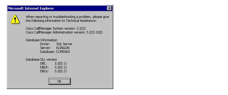
Cisco CallManager Software Release
Catalyst 6000 Switch Configuration
Application Note
NEC 2400 ICS Rel J 5.8 PBX with CallManager using 6608-E1 PRI EURO Gateway
This application note illustrates connectivity for NEC 2400 ICS Rel J 5.8 PBX with CallManager using 6608-E1 PRI EURO Gateway.
Introduction
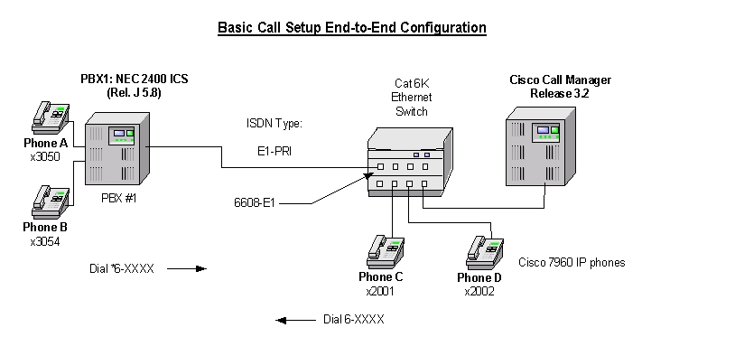
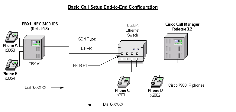
The network topology diagram presented in Figure 1 illustrates the test set-up for end-to-end interoperability with the Cisco CallManager connected to the PBX via 6608-E1 PRI link as the Gateway
Key test environment parameters:
•
Connectivity is achieved by using the PRI EURO protocol type on the gateway and NEC/ETSI switch type on the NEC 2400 PBX. Though the NEC 2400 can be configured as either NETWORK (Master) or USER (Slave) side, this is not recommended and the NEC TAC center will not resolve a case presented with NEC set as NETWORK side.
•
•
Network Diagram
Figure 1
Network Test Topology
Limitations
Calling Name and Number Feature
Calling Name delivery and presentation feature are not supported by the NEC 2400 ICS PBX.
When calling from Cisco 7960 IP phone to NEC digital phone, both phones display Calling Number after the call is answered as expected.
When calling from NEC digital phone to Cisco 7960 IP phone, the Cisco IP phone displays Connected Number after the call is answered. NEC phone however does NOT get updated when the call is answered. It displays the numbers being dialed instead (i.e. Access Code + extension number). It was verified using an ISDN protocol analyzer that the CCM was not sending "Connected Number" information in the CONNECT message back to PBX.
System Components
Hardware Requirements
Cisco Hardware:
•
•
NEC 2400 ICS PBX:
•
Software Requirements
•
•
Feature
Key features supported:
•
Key features not supported:
•
•
Configuration
Sequence of configuration tasks:
3.
NEC 2400 ICS Configuration
The NEC requires a substantial amount of programming and circuit card switch settings to properly install E1 PRI. It is beyond the scope of this document to provide the entire configuration, therefore the NEC information below is mostly helpful for NEC techs. If further assistance is required, the entire configuration of our lab PBX can be found in EDCS document # EDCS-207455. The EDCS document provides the programs required for E1 ISDN circuit setup, all the switch settings for all cards on our Lab NEC and fairly complete configuration listings (List Ups).
Note:
Configure in the following sequence:
1.
2.
Route (ARTD) Configuration
Below are the Route settings found in ARTD. Route 12 is the B channel and Route 13 is the D channel. Please refer to EDCS document # EDCS-207455 for complete details for configuration.
[LRTD] CISCO TEST FACILITY 02/05/10 PAGE: 5* ROUTE CLASS DATA LIST *------- R O U T E N U M B E R -------CDN FUNCTION 11 12 13 14 151 OSGS 7 0 0 0 02 ONSG 3 2 0 2 23 ISGS 7 0 0 0 04 INSG 3 2 0 2 25 TF 3 3 3 3 36 TCL 4 4 4 4 47 L/T 1 1 1 1 18 RLP 2 2 0 2 09 TQ 0 0 0 0 010 SMDR 0 1 1 1 111 TD 0 0 0 0 012 DR 0 0 0 0 013 AC 1 1 0 1 014 TNT 0 0 0 0 015 LSG 5 12 13 12 1316 SMDR2 0 0 0 0 017 H/M 0 0 0 0 018 MC 0 0 0 0 019 ANI 0 1 1 1 020 D 0 0 0 0 021 MSB 0 0 0 0 022 MSW 0 0 0 0 023 TR 0 0 0 0 024 OC 0 0 0 0 025 R/L 0 0 0 0 026 RVSD 0 0 0 0 027 TL 0 0 0 0 028 ANS 0 1 1 1 129 TELP 0 0 0 0 030 PAD 0 4 7 4 731 OGRL 0 1 1 1 132 ICRL 0 1 1 1 133 HD 0 0 0 0 034 GUARD 0 1 1 1 135 WINK 0 0 0 0 036 VAD 0 0 0 0 037 CLD 0 0 0 0 038 FA 0 0 0 0 0[LRTD] CISCO TEST FACILITY 02/05/10 PAGE: 6* ROUTE CLASS DATA LIST *------- R O U T E N U M B E R -------CDN FUNCTION 11 12 13 14 1539 BC 0 0 0 0 040 TCM 0 0 0 0 041 TDMQ 0 0 0 0 042 TRSC 0 0 0 0 043 BT 0 1 0 1 144 PRV 0 0 0 0 045 A/D 0 1 1 1 146 CW 0 0 0 0 047 TPQ 0 0 0 0 048 BL 0 0 0 0 049 TRKS 0 1 1 0 050 DPLY 0 1 1 1 151 ACD 0 0 0 0 052 2W/4W 1 0 0 0 053 FAAT 0 0 0 0 054 GW 0 0 0 0 055 TCMA 0 0 0 0 056 SMDR3 0 0 0 0 057 HDT 0 0 0 0 058 CD 0 0 0 0 059 CCH 0 0 0 0 060 TC/EC 0 0 0 0 061 IRE 0 0 0 0 062 SCR 0 0 0 0 063 LYER1 0 1 1 1 164 NET 0 1 0 0 065 INT 0 4 4 4 466 DC 0 4 4 4 467 HKS 0 0 0 0 068 SCF 0 0 0 0 069 SMDR4 0 0 0 0 0Cisco CallManager Configuration
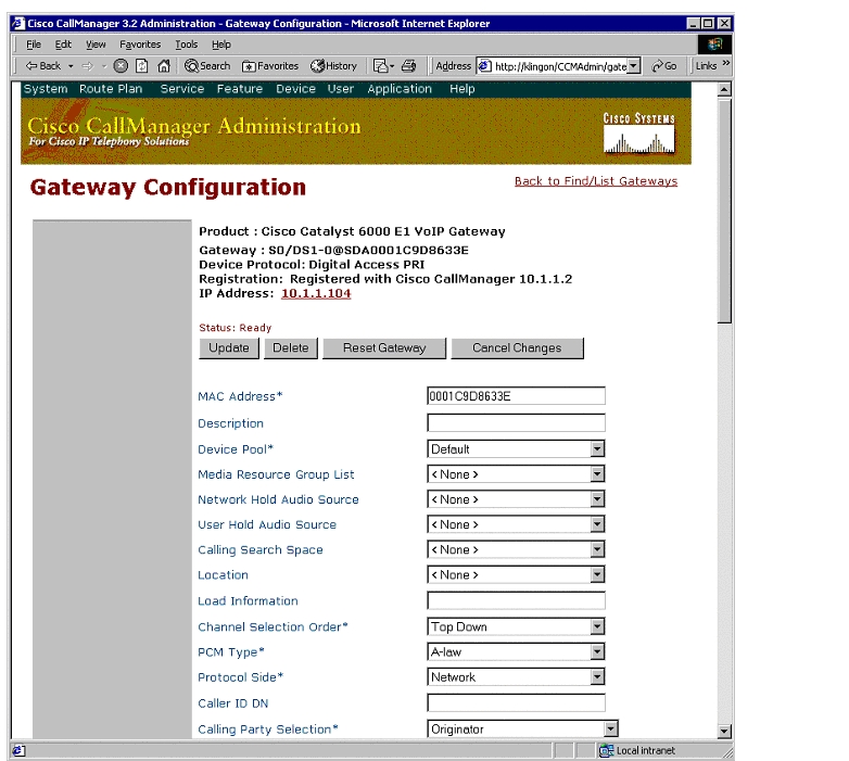
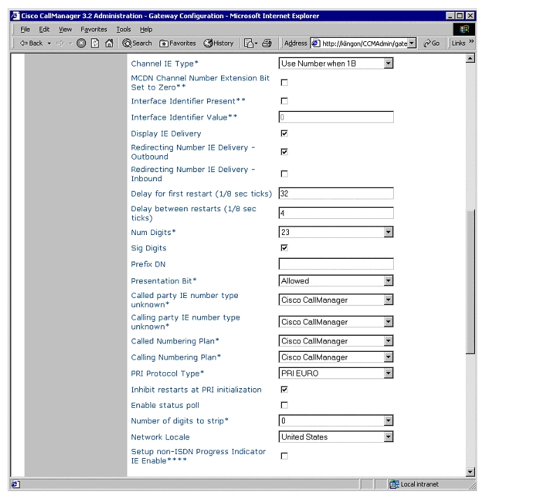
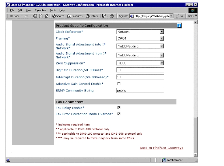
6608-E1 Gateway Configuration
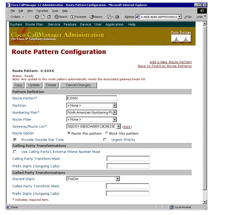
Route Pattern Configuration
Appendix A
Cisco CallManager Software Release
NEC 2400 ICS Software Release
Software Release:
VERSION ISSUE DATEJ 05.80 00/06/20 GenericF 01.00 96/04/26 Boot ROMCatalyst 6000 Switch Configuration
Console> (enable) sh versionWS-C6006 Software, Version NmpSW: 5.5(6a)Copyright (c) 1995-2001 by Cisco SystemsNMP S/W compiled on Feb 23 2001, 10:23:18System Bootstrap Version: 5.3(1)Hardware Version: 2.0 Model: WS-C6006 Serial #: TBA04511172Mod Port Model Serial # Versions--- ---- ------------------- ----------- --------------------------------------1 2 WS-X6K-SUP1A-2GE SAD05010NBK Hw : 7.0Fw : 5.3(1)Fw1: 5.4(2)Sw : 5.5(6a)Sw1: 5.5(6a)WS-F6K-PFC SAD05020221 Hw : 1.13 48 WS-X6348-RJ-45 SAD04420N7B Hw : 1.4Fw : 5.4(2)Sw : 5.5(6a)WS-F6K-VPWR Hw : 1.04 24 WS-X6624-FXS SAD050203M8 Hw : 3.0Fw : 5.4(2)Sw : 5.5(6a)HP : A00203010038; DSP : A003Q031 (3.6.15)6 8 WS-X6608-E1 SAD04380DW1 Hw : 1.1Fw : 5.4(2)Sw : 5.5(6a)HP1: D00403010044; DSP1: D005Q031 (3.6.15)HP2: D00403010044; DSP2: D005Q031 (3.6.15)HP3: D00403010044; DSP3: D005Q031 (3.6.15)HP4: D00403010044; DSP4: D005Q031 (3.6.15)HP5: D00403010044; DSP5: D005Q031 (3.6.15)HP6: D00403010044; DSP6: D005Q031 (3.6.15)HP7: D00403010044; DSP7: D005Q031 (3.6.15)HP8: D00403010044; DSP8: D005Q031 (3.6.15)DRAM FLASH NVRAMModule Total Used Free Total Used Free Total Used Free------ ------- ------- ------- ------- ------- ------- ----- ----- -----1 65408K 37340K 28068K 16384K 11546K 4838K 512K 198K 314KUptime is 127 days, 7 hours, 31Console> (enable)Console> (enable) sh moduleMod Slot Ports Module-Type Model Sub Status--- ---- ----- ------------------------- ------------------- --- --------1 1 2 1000BaseX Supervisor WS-X6K-SUP1A-2GE yes ok3 3 48 10/100BaseTX Ethernet WS-X6348-RJ-45 yes ok4 4 24 FXS WS-X6624-FXS no ok6 6 8 E1 WS-X6608-E1 no okMod Module-Name Serial-Num--- ------------------- -----------1 SAD05010NBK3 SAD04420N7B4 SAD050203M86 SAD04380DW1Mod MAC-Address(es) Hw Fw Sw--- -------------------------------------- ------ ---------- -----------------1 00-04-c0-f8-42-02 to 00-04-c0-f8-42-03 7.0 5.3(1) 5.5(6a)00-04-c0-f8-42-00 to 00-04-c0-f8-42-0100-04-9b-f0-78-00 to 00-04-9b-f0-7b-ff3 00-02-fc-20-5e-50 to 00-02-fc-20-5e-7f 1.4 5.4(2) 5.5(6a)4 00-03-32-ba-2e-35 3.0 5.4(2) 5.5(6a)6 00-01-c9-d8-63-3e to 00-01-c9-d8-63-45 1.1 5.4(2) 5.5(6a)Mod Sub-Type Sub-Model Sub-Serial Sub-Hw--- ----------------------- ------------------- ----------- ------1 L3 Switching Engine WS-F6K-PFC SAD05020221 1.13 Inline Power Module WS-F6K-VPWR 1.0Console> (enable)Console> (enable) sh port 6/1Port Name Status Vlan Duplex Speed Type----- ------------------ ---------- ---------- ------ ----- ------------6/1 connected 1 full 2.048 E1Port DHCP MAC-Address IP-Address Subnet-Mask-------- ------- ----------------- --------------- ---------------6/1 enable 00-01-c9-d8-63-3e 10.1.1.104 255.255.255.0Port Call-Manager(s) DHCP-Server TFTP-Server Gateway-------- ----------------- --------------- --------------- ---------------6/1 10.1.1.2 10.1.1.2 10.1.1.2 10.1.1.7Port DNS-Server(s) Domain-------- ----------------- -------------------------------------------------6/1 - -Port CallManagerState DSP-Type-------- ---------------- --------6/1 registered C549Port NoiseRegen NonLinearProcessing----- ---------- -------------------6/1 enabled enabledConsole> (enable)Test Configuration
Figure 2
Test Topology
As shown in the diagram above, an NEC 2400 ICS PBX was connected via an ISDN E1 PRI link to a Cisco 6608-E1 Gateway, which in turn, was connected to an Ethernet switch. The interoperability testing involved Layers 1, 2 and 3 on the ISDN PRI link between a Cisco 6608-E1 and the PBX.
Layers 2 & 3 (Q.921 and Q.931)
Layer 2 and 3 packet exchanges were monitored using an Acacia Clarinet protocol analyzer, bridged across the PRI link in high impedance mode.
Layer 2 Q.921 packets were monitored to ensure that each PBX/6608-E1 software configuration properly exchanged SABME/UA packets to initialize the ISDN link, and then RR packets were exchanged every 30 seconds.
Layer 3 Q.931 packets were monitored to ensure that the appropriate call setup/teardown packets were exchanged for each configuration, and that the SETUP packets contained the mandatory Information Elements with the necessary details, as well as optional IEs such as Calling Name and Number.
Telephone calls were made end-to-end in both directions through the Cisco 6608-E1 Gateway, and a check was made to ensure that there was an audio path in both directions for each call.
User/Network Settings
The Cisco 6608-E1 Gateway with ISDN protocol type setting of PRI EURO supports both protocol sides by selecting "Network/User" in the Protocol Side field when configuring the Gateway via CCM. The NEC 2400 ICS PBX supports "USER" protocol side.
Appendix B
Test Results
Testing was performed by Test Engineer(s): Samir Batio and Bob Graves, March 11, 2002
Test Setup
Test configuration:
•
•
Table 2 Test Setup Switch and Gateway Settings
ETSI / User
PRI EURO / Network
Table 3 Basic Calls: (Enbloc Sending)
Yes
Yes
No
No1
No
Yes
Yes
No
Yes
No
1 CCM does not support sending "Connected Number" information in the connect message back to PBX.
2 The NEC 2400 with switch-type setting of ETSI for the PRI interface does not support "Calling Name" presentation feature.
1 NEC 2400 ICS PBX does not support Overlap sending/Receiving mode.
![]()
![]()
![]()
![]()
![]()
![]()
![]()
![]()
Posted: Thu Sep 6 13:32:26 PDT 2007
All contents are Copyright © 1992--2007 Cisco Systems, Inc. All rights reserved.
Important Notices and Privacy Statement.