|
|

The ISDN PRI package provides call processing and administrative support for ISDN PRI services. ITU Q.921/931 access to T1 ISDN switch types (4ESS, 5ESS, NI-2, NTI, NTT) and E1 ISDN switch types (EURO, QSIG, TS014) can be configured for each Interface Controller Card (ICC) Primary Rate Interface (PRI) ISDN span in the system.
ICC cards are available in three configurations supporting four, eight, or sixteen PRI ISDN spans, depending upon the I/O module with which they are used.
Four, eight, and sixteen span I/O modules each consist of four groups of spans. Each span is defined as an RLS—rack, level, slot—address. The format of the RLS address is x x x-x-x, where the first x represents the rack, the second x represents the level, and the last three represent the slot. A four span I/O module, referred to as a 4x I/O module, has one span in each of the four groups, an 8x I/O module has two spans in each group, and a 16x I/O module has four spans in each group. Table 1-1 is a representation of what the RLS addresses of 4x, 8x, and 16x ICC PRI ISDN I/O module spans would be, if the ICC card and I/O module are located in slot 15 of a VCO system chassis.
Table 1-1 Rack, Level, and Slot Addresses of 4x, 8x, and 16x I/O Module Spans
|
||||||||||||||||||||||||
Each T1 ICC PRI ISDN span provides 23 bearer channels (B-channels) and a single data channel (D-channel) for transmission of ISDN control messages (23 B+D). For T1 ISDN switch types, users may select D3/D4 format, or extended super frame (ESF) format on a per span basis, with bipolar 8-zeros signaling (B8ZS) bit encoding. The D-channel is not inverted.
Each E1 ICC PRI ISDN span provides 30 B-channels and a single D-channel for transmission of ISDN control messages (30 B+D). For E1 ISDN switch types, users may select CRC4 format, or non-CRC4 format on a per span basis, with high-density bipolar 3-zeros signaling (HDB3) bit encoding. The D-channel is not inverted.
ICC PRI ISDN span operation supports the Physical, Data Link, and Network Layers (1, 2, and 3) of the Open Systems Interconnection (OSI) model to provide interface with ISDN D-channel protocols. The ICC application software, stored on the system hard disk, is downloaded to the ICC PRI ISDN span by the generic software only when a new version is available; otherwise, the application is stored in flash memory on the ICC card. This application on the ICC interacts with the call processing functions running on the system controller.
Full system administration support is provided to allow ICC PRI ISDN span configuration, alarm detection and processing, and span maintenance functions. Enhancements to system call processing allow ISDN features and capabilities to be added to an application with no effect on existing applications. Use the ISDN message templates and rule processing to enhance programmable reporting of ISDN events and facilitate construction of outgoing D-channel messages. Use the ISDN supervision templates to control outgoing ISDN calls. These features support not only pure ISDN calls, but also calls which use a mixture of ISDN and non-ISDN resources. These mixed resource cases, called interworking scenarios, allow the system to act as a gateway between the ISDN and traditional services networks.
Every attempt has been made to provide full ISDN PRI support for T1 switch types (4ESS, 5ESS, NI-2, NTI, NTT) and E1 switch types (EURO, QSIG, TS014). Contact the Cisco Systems TAC if your application encounters any compatibility problems.
The ISDN PRI package consists of the following components:
The ISDN PRI NFAS package consists of the following components:
Verify the contents of the package. If any of the components listed above are missing, contact the Cisco Systems TAC.
The ISDN NFAS option supports AT&T 4ESS, AT&T 5ESS, NI-2, and NTI (DMS-100/250) switches and allows a single D-channel to control up to 20 interfaces.
Assign the ICC PRI ISDN spans to NFAS groups through the system administration screens. Each NFAS group consists of an interface containing the primary D-channel and up to 19 additional interfaces—ICC T1 spans configured for clear channel signaling. You can configure up to 37 NFAS groups, each with a separate primary D-channel. An optional backup D-channel can also be configured for each group.
The NFAS option details are contained in "Non-Facility Associated Signaling (NFAS)."
This section provides system requirements for running the ISDN PRI package. These requirements are categorized by hardware and software. Contact the Cisco Systems Customer Response Center for any site-specific concerns.
The ISDN PRI package Version 5.1 or higher requires a VCO/4K system equipped with ICC card(s) and their corresponding I/O modules. Refer to the "Software and Hardware Configuration and Installation Instructions" section for hardware configuration requirements and installation instructions.
The ISDN PRI package Version 5.1 or higher requires system software V5.1 FSR00 PUN24, or higher. Refer to the "Software and Hardware Configuration and Installation Instructions" section for software configuration requirements and instructions.
This section details the procedure for installing ISDN PRI and ISDN NFAS. You should have a working knowledge of system operation, and the VCO system should be running system V5.1 FSR00 PUN24, or higher.
 |
Note If you are not installing either, or both, the ISDN PRI and the NFAS diskettes as part of a system software installation or upgrade, follow the installation instructions below; otherwise, refer to the Cisco VCO/4K System Software Release Notes for installation instructions. |
The software needed to run ISDN PRI on your system is included as part of the system software. However, you need the two Optional Software diskettes, which contain an installation utility, to enable ISDN PRI on your system. This utility consists of an installation program and a set of DOS-like disk utilities that perform operations such as database backup during the installation. Read and understand all the material contained in this section before proceeding with the installation.
The system must be off line before you can perform the installation procedure. Estimated time for the completion of the software installation is 10 minutes (20 minutes for a redundant system).
Use the following tools during your installation:
In addition, you must use a local console session to accomplish the installation. For VCO/4K and VCO/20 systems, connect a dumb terminal, a PC with dumb terminal emulation, or a terminal server to the Port 1/Console port which is located on the back end of the Storage/Control I/O module. For VCO/80 systems, connect a dumb terminal, a PC with dumb terminal emulation, or a terminal server to the Serial Port 1 Console port on the CPU-TM module.
Refer to the following manuals during installation:
The ISDN NFAS option is enabled by installing both the ISDN PRI diskette and the ISDN NFAS diskette. Now you can perform the preinstallation procedures for your nonredundant, or redundant, VCO system. Refer to the following sections for your system's configuration.
Ensure that your nonredundant system meets the following configuration guidelines before you can successfully install the ISDN PRI and/or ISDN NFAS software applications.
|
Note The system must be fully powered up. |
Step 2 Log in to the active (ACT) side of the system, and ensure that the Redundant System feature flag, found in the System Features screen, is set to N; if not, set the feature flag to N to disable this feature.
Step 3 Set the local console to 9600 kbps, if it is not set already. The local console must be set to 9600 kbps for you to see all CPU reboot messages during the installation. To set the console:
a. Log in to the system and access the System Configuration Menu screen.
b. Select A, Peripheral Configuration, and set the local TTY baud rate to 9600.
You have completed the preinstallation procedures for nonredundant systems. Now you can install the ISDN PRI and/or ISDN NFAS diskettes on your VCO system. Refer to the "ISDN PRI and/or ISDN NFAS Installation Instructions for Nonredundant and Redundant VCO Systems" section for installation instructions.
Ensure that your redundant system meets the following configuration guidelines before you can successfully install the ISDN PRI and/or ISDN NFAS software applications.
|
Note The system must be fully powered up. |
Step 2 Log in to the active (ACT) side of the system, and ensure that the Redundant System feature flag, found in the System Features screen, is set to Y; if not, set the feature flag to Y to enable this feature.
Step 3 Set the local console to 9600 kbps, if it is not set already. The local console must be set to 9600 kbps for you to see all CPU reboot messages during the installation.
a. Log in to the system and access the System Configuration Menu screen.
b. Select A, Peripheral Configuration, and set the local TTY baud rate to 9600.
Step 4 Make the A-side active. If the state of the system is A-SBY/B-ACT, log in to the B-side and execute the Switch ACT System to SBY command (selection E) of the Maintenance Menu screen. Otherwise, proceed to the Step 5.
Step 5 Position the Select toggle switch on the AAC to the A setting.
Step 6 Verify that the system console indicates the A-ACT/B-SBY state, which can take up to 60 seconds for the system to update.
Step 7 Verify that the A Active LED is lit (green) and the B Active LED is not lit, on the AAC.
Step 8 Verify that there are no alarms marked as fatal or critical by accessing the System Alarms Display screen and inspecting the log file.
|
Note All fatal and critical alarms must be resolved before attempting this software installation. In addition, any alarm (fatal, critical, major, or minor) which contains the phrase Update Channel or the term UPD, must be resolved. |
Step 9 Verify a received "FRMxxx ALM080: Update Channel Failure" alarm message in the log file.
The B-side must be taken off line before the software installation can begin. This action generates an "FRMxxxALM080: Update Channel Failure" alarm message. This message is verified in one of two ways, depending upon which system you are using:
The "FRMxxx ALM080: Update Channel Failure" alarm message clears after the installation is completed on the B-side.
Step 10 Log out of the A-side.
You have completed the preinstallation procedures for redundant systems. Now you can install the ISDN PRI and/or ISDN NFAS diskettes on your VCO system.
Complete the following steps to install the ISDN PRI package and/or ISDN NFAS package on your VCO system:
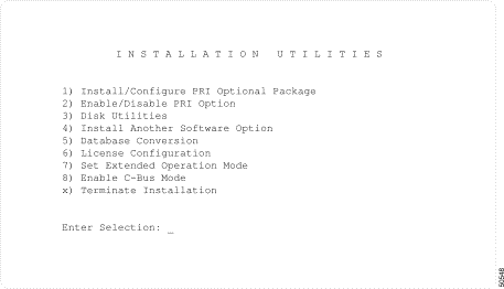
Step 2 Press the A RESET push button on the AAC. The A-side boots from the boot code present on the ISDN PRI diskette. The system controller (CPU) outputs a series of boot messages, and then the Installation Utilities screen appears (see Figure 1-1).
Step 3 Perform a database backup. Refer to the "Performing a Database Backup" section for database backup instructions.
Step 4 Type 1 and press Return, in the Installation Utilities screen. The following message appears:
Step 5 Type N and press Return. The following messages are displayed:
The Installation Utilities screen appears (see Figure 1-1).
Step 6 Type 4 and press Return, if you are installing the ISDN NFAS package; otherwise, proceed to Step 11 to terminate the installation procedure. The following messages are displayed:
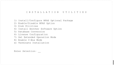
Step 7 Insert the ISDN NFAS diskette and press Return. The Installation Utilities screen is displayed (see Figure 1-2).
Step 8 Type 1 and press Return. The screen clears and the following message is displayed:
Step 9 Type N and press Return. The following messages are displayed, and then the Installation Utilities screen display appears (see Figure 1-2):
Step 10 Remove the diskette.
Step 11 Type x and press Return to terminate the installation. The following message is displayed:
Step 12 Type Y and press Return. The following messages are displayed:
|
Note You may see the "Reset System NOW!" message. If you see the message, press the A RESET push button on the AAC. If you do not see the message, do not press the RESET button—the system reboots automatically in this case. |
Step 13 Proceed to Step 14 if you are installing the software on the A-side of a redundant system.
Proceed to "Software and Hardware Configuration and Installation Instructions" section if you are installing the software on the A-side of a nonredundant system, or if you are installing the software on the B-side of a redundant system. Your installation is complete; do not proceed further in these instructions.
Step 14 Move the console to the B-side.
|
Note When installing the software on the B-side, you must leave the Select toggle switch on the Alarm Arbiter Card (AAC) at the A setting. |
Step 15 Insert the ISDN PRI diskette in the B-side floppy disk drive.
Step 16 Configure your system's hardware. Your configuration procedure is dependent upon which system you are using.
The Installation Utilities screen is displayed. Proceed to step 4 of these instructions and complete the installation.
You have completed the ISDN PRI and ISDN NFAS installation procedures for your system. The system finishes rebooting and the login screen is displayed.
For redundant systems, verify that file synchronization has occurred. Perform the following steps:
Step 2 Access the log file and verify that the RED20:ACT FILE SYNC COMPLETED message is present from the standby side.
Step 3 Access the System Alarms Display screen and verify that there are no alarms containing the phrase Update Channel, or the term UPD.
Step 4 Position the Select toggle switch on the AAC card to the AUTO setting.
Now you can configure the software and install the hardware for the ICC PRI ISDN spans. Refer to "Software and Hardware Configuration and Installation Instructions" section for further information and instructions.
To perform a database backup with the Disk Utilities screen, complete the following steps.
|
Note Before making the backup, prepare a DOS-formatted 3.5-inch high-density diskette on which you have created a DBASE directory. You can create the directory with the standard DOS utility MKDIR. |
Step 2 Insert a formatted high-density diskette into the floppy drive.
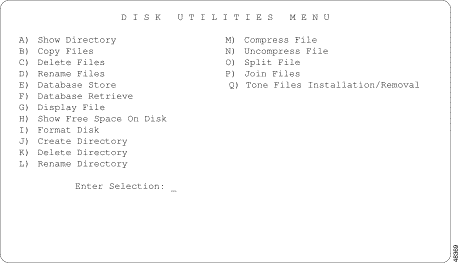
Step 3 Type 3 and press Return. The Disk Utilities Menu screen is displayed (see Figure 1-3).
Step 4 Type 2 and press Return. The following message appears:
Step 5 Type c:/dbase/*.tbl and press Return. The following message appears:
Step 6 Type a:/dbase and press Return. The following message appears:
When all files are copied, the Disk Utilities Menu screen is displayed (see Figure 1-3).
Step 7 Verify that the database was backed up onto the floppy disk as follows:
Step 8 Type 15 and press Return to exit the Disk Utilities Menu screen and return to the Installation Utilities screen.
Step 9 Remove the backup diskette.
|
Note For redundant systems, you do not need to back up the database on the B-side. Backing up the database on the A-side is sufficient. |
The database backup procedure is now complete. Continue with the installation procedures described in the preceding sections.
The software and hardware associated with the ICC PRI ISDN package must be configured and installed according to the following steps:
Step 2 Configure the ICC PRI ISDN span(s) in the database. Refer to "System Administration Support," for instructions.
Step 3 Insert the ICC I/O module into the appropriate slot at the rear of the VCO system chassis.
Step 4 Insert the ICC card into the corresponding slot at the front of the VCO system chassis.
You must perform two further configuration issues to enable ISDN call processing on your system.
Contact the Cisco Systems TAC if you encounter any difficulties during the installation process.
Cisco Systems has identified and evaluated functional considerations in the ISDN PRI and ISDN NFAS software packages. This section provides explanations and, where applicable, workarounds for functional considerations in the areas that follow. These considerations are in addition to the known functional constraints, which are contained in the Cisco VCO/4K System Software Release Notes.
The use of the Null Outpulse Rule in the ISDN Port Control ($49) command (null outpulse rule 0) is not supported for ISDN channels.
For interworking scenarios in which the incoming port is an ISDN B-channel and the outgoing is another type of interface, the condition token ANSBK (answerback) cannot be used in conjunction with the TIME event to satisfy the supervision template. In this case, the incoming B-channel remains in CP_WANS state when the event occurs. The call does not go stable; no information is transferred to the SBY controller (if the system is equipped with redundant system controllers).
The following functional considerations have been identified in D-channel message handling:
The following functional considerations have been identified in PRI synchronization and timing:
All PRI diagnostic mode utilities are performed via the Card Maintenance screen, and performed to the ICC card. Refer to the Cisco VCO/4K System Administrator's Guide for further information.
Switch Types Supporting NFAS Operation—The four Switch Type settings on the ICC ISDN Span Configuration screen which are supported in NFAS are
All other switch types (ICC-T1 PRI/NTT, ICC-E1 PRI/NET5 (EURO), ICC-E1 PRI/QSIG, and ICC-E1 PRI/TS014) are not supported with NFAS operations. Verify that all ICC PRI ISDN spans placed in NFAS groups are configured for appropriate connections.
This document describes and defines the ISDN configuration implemented for your system. For general ISDN information and details on ISDN message and information element structure, refer to the International Telecommunications Union's document ITU-T Q.931. Implementation of ISDN protocols on the ICC was based on information contained in the following documents.
Refer to the following documents for further information on the National ISDN-2 (NI-2) protocol:
Refer to the following documents for further information on the AT&T #4 Electronic Switching System, and AT&T #5 Electronic Switching System (4ESS and 5ESS) protocols:
Refer to the following document for further information on the Northern Telecom, Inc., (NTI) protocol:
Refer to the following document for further information on the Nippon Telegraph and Telephone Corporation (NTT) protocol:
Refer to the following documents for further information on the European Telecommunications Standard network-userside-interface, EURO, protocol:
Refer to the following documents for further information on the Private Integrated Signaling System No. 1 (PSS1) Q-reference Point Signaling (QSIG) protocol:
Refer to the following document for further information on the Australia Communications Authority (ACA) Technical Standard 014 (TS 014) protocol:
![]()
![]()
![]()
![]()
![]()
![]()
![]()
![]()
Posted: Fri Jan 23 12:12:47 PST 2004
All contents are Copyright © 1992--2004 Cisco Systems, Inc. All rights reserved.
Important Notices and Privacy Statement.