|
|

This chapter describes the Non-Facility Associated Signaling (NFAS) option available for system ISDN call processing. The following topics are discussed:
The functions and screens described in this chapter can only be used when the NFAS option is installed on the system. Installation instructions for the NFAS option are discussed in the "ISDN PRI and ISDN NFAS Installation" section.
Standard T1 ISDN PRI consists of 24 channels—where a single signaling channel (D-channel) controls the remaining 23 bearer channels (B-channels) on the interface. In system terms, this means ports 1 through 23 on the ICC ISDN span (B-channels) are controlled by port 24 (D-channel). The NFAS option extends D-channel control to B-channels not resident on the same interface. This allows a single D-channel to control up to 20 interfaces (a maximum of 479 B-channels, or a maximum of 478 with one B-channel as a backup).
The NFAS option does not support all ICC ISDN span types. Table 5-1 lists the ICC ISDN span types and indicates their level of NFAS support.
The following features are supported for NFAS operation:
A single system can simultaneously support both standard 23B+D ICC ISDN spans and the NFAS operation.
ICC ISDN spans and ICC T1 spans are assigned to NFAS groups using the system administration functions. Two screens are provided for NFAS configuration—the NFAS Group Summary screen and the NFAS Configuration screen. Each NFAS group consists of an interface containing the primary D-channel and up to 19 additional interfaces (supporting a maximum of 479 B-channels). Up to 37 NFAS groups can be configured, each with a separate primary D-channel. An optional backup D-channel can also be configured for each group (supporting a maximum of 478 B-channels, with one B-channel as a backup).
Instructions for using the NFAS administration screens are provided in the "NFAS System Administration" section.
Users have the option of designating a backup D-channel (usually called the D2 channel) for each NFAS group. This allows one D-channel to be active (controlling the NFAS group) while another standby D-channel is available should a D-channel switchover occur. The following conditions can cause a D-channel switchover:
If a backup D-channel is defined for the group, all stable calls are maintained when control is passed to the standby D-channel. The standby D-channel transitions from the standby (STBY) state to the in service (IS) state, while the active D-channel transitions from IS to the maintenance busy (MB) state and then to the out of service (OOS) state.
 |
Note To ensure D-channel redundancy, the ISDN interfaces must be provisioned identically at both the system and the network ends. The ICC ISDN span containing the primary D-channel must be connected to the primary (D1) line, while the ICC ISDN span containing the backup D-channel must be connected to the backup (D2) line for the initial contacts and channel switchovers to occur properly. |
When a D-channel switchover occurs, a 40-second system timer (T321) is started. If the standby D-channel transitions to IS before the timer expires, all stable calls are maintained and the timer is cancelled. During the switchover, calls that are not stable are cleared by the system. The system then sends an ISDN Port Change of State ($EA) report to the host for each call cleared. If the timer expires (switchover occurred but was not successful), all calls are cleared. The system generates a System Card Status ($D9) report for each interface span in the group.
Manual D-channel switchovers are also possible. You can use a command field on the NFAS Configuration screen to force the standby D-channel to assume control of the NFAS group selected. A manual switchover has the same effect on ISDN calls in progress as an automatic switchover.
Refer to "Valid Information Elements for I FLD and D FLD Action Tokens," for descriptions of D-channel state processing on the primary and backup D-channels during channel initialization and switchovers. The NFAS option follows network requirements for backup D-channel service as discussed in Annex F of the AT&T Integrated Services Digital Network (ISDN) Primary Rate Interface Specification (TR 41449) and Appendix F of the ISDN Primary Rate User-Network Interface Specification (NIS A211-1). Refer to these publications for more information on switchover timing and D-channel state transitions.
NFAS is defined and configured for your system through the use of two system administration screens—the NFAS Group Summary screen and the NFAS Configuration screen.
The NFAS Group Summary screen allows you to perform the following functions:
Up to 37 NFAS groups can be configured for the system from this screen.
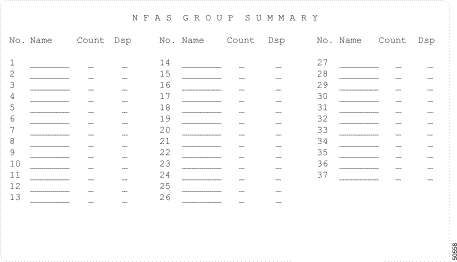
To access the NFAS Group Summary screen (see Figure 5-1) from the Database Administration menu, type L and press Enter. The cursor is located in the first Name field.
The NFAS Group Summary screen consists of one screen. Press Tab and < to move between Name fields. Press Next Field and Prev Field to move between the Name and Dsp fields. Press Print Screen to obtain a hard copy of any screen.
The NFAS Group Summary screen has the following fields:
No.—Display only. Indicates the number of the NFAS group. Possible values for this field range between 1 and 37.
Name—Data entry via main keyboard. Optional entry that determines the name of the NFAS group. This field accepts up to eight alphanumeric characters, either upper- and/or lowercase.
Count—Display only. Indicates the number of B-channels currently in this NFAS group. The number is updated when changes are made to the group via the NFAS Configuration screens. The value for this field can be a number between 0 and 479 (or between 0 and 478 with a backup D-channel span).
Dsp—Data entry via main keyboard, access to another screen(s). Display group—provides access to the NFAS Configuration screens. Any character on the main keyboard is valid for entry. Refer to the "Changing NFAS Group Summary Screen Field Parameters" section for instructions on using this field.
You can change the Name field for each group by using the NFAS Group Summary screen. To change this field, complete the following steps:
Step 2 Type the Name information, then press Next Field. The cursor moves to the Dsp field.
Step 3 To assign a name to another NFAS group, press Next Field and repeat Step 2. Use Tab and < to move between Name fields.
Step 4 When all changes have been made, press Enter. The following message is displayed:
Step 5 Press Enter. The following message is displayed, and the database is automatically updated.
Step 6 To display or edit an NFAS group configuration, use the Next Field and Prev Field keys to position the cursor in the Dsp field corresponding to that group, type any character and press Enter (the NFAS Configuration screen is described in the "NFAS Configuration Screen" section). If no further NFAS group changes are to be made, press Exit or Prev Menu to return to the Database Administration menu.
To leave the NFAS Group Summary screen without making any changes, press Exit, Prev Menu, or Main Menu. No changes are made to the database unless you press Enter.
You can access the following screens from the NFAS Group Summary Screen:
To access the NFAS Configuration screen, complete the following steps:
Step 2 Type any character and press Enter.
Use the NFAS Configuration screen to create NFAS groups. An NFAS group consists or one or two ICC ISDN spans—the primary span and the backup span. The D-channel on the active span, primary or backup, receives the call control messages for the entire NFAS group. All other interfaces in the NFAS group are ICC T1 spans. Each group consists of the following components:
The following configuration rules apply to NFAS groups:
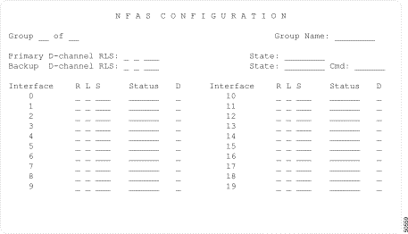
The NFAS Configuration screen is shown in Figure 5-2. The cursor is located in the Primary D-channel RLS field.
The NFAS Configuration screen consists of a single screen.
Press Prev Field and Next Field keys to move between fields for an interface, and from the last field for an interface to the first field for the next interface. Press Tab and < to move between interface R L S fields. Press Prev Screen and Next Screen to move through the NFAS Group displays. Press Print Screen to obtain a hard copy of this screen.
The NFAS Configuration screen contains the following fields:
Group__of__—Display only. Indicates the number of the NFAS group currently displayed. Interpret this field as: Group n of 37, where n is a numerical value in the range from 1 to 37.
Group Name—Display only. Indicates the name assigned to the currently displayed NFAS group. This field can be changed using the NFAS Group Summary screen, and can contain up to eight alphanumeric characters, upper- and/or lowercase.
Primary D-channel RLS—Data entry via main keypad. Indicates the rack, level, slot (RLS) address of the span which contains the D-channel designated as the primary control channel for the currently displayed NFAS group. Refer to the "ISDN Primary Rate Interface Package" section for span location conventions.
|
Note An ICC ISDN span RLS address must be entered in this field for the NFAS group to function. This span must be configured as a 23B+D PRI. |
State—Display only. This field indicates the current state of the primary D-channel. With the exception of the manual out of service (MOOS) state, the state transitions are controlled by link signaling between the system and the network interface and cannot be set via system administration. Possible values for this field are listed in Table 5-2.
Backup D-channel RLS—Data entry via main keyboard. Optional entry that indicates the rack, level, slot (RLS) address of the span which contains the D-channel designated as the backup control channel for the currently displayed NFAS group. Refer to the Cisco VCO/4K System Administrator's Guide for span location conventions.
State—Display only. This State field indicates the current state of the backup D-channel. Possible values for this for this field are listed in Table 5-2.
Cmd—Data entry via Select key. Allows the user to change the state of the backup D-channel using one of three commands, listed in Table 5-3. Use this field to perform a manual switchover between the primary and backup D-channels, and to place the primary or backup D-channel into and out of the manual out of service (MOOS) state.
|
Note The command selections available to the user depend upon the current state of the standby D-channel. For example, if the D-channel is currently in MOOS state, the only selection available is ACTIVATE. |
Table 5-3 Cmd Field Commands and Resulting Backup D-channel State Changes
Interface—Display only. Specifies the interface number of the ICC ISDN span or the ICC T1 span being added to the NFAS group. Up to 20 interfaces, including those containing the primary and backup D-channels, are listed for each NFAS group. Corresponding R L S, Status, and D fields are listed for each interface. The interface number must correspond to the provisioning of the interfaces at the far-end connection.
R L S—Data entry via main keyboard. Indicates the rack, level, slot (RLS) address of the span. Refer to the Cisco VCO/4K System Administrator's Guide for the span location conventions.
|
Note The primary D-channel and optional backup D-channel (if defined) must be entered in the Interface RLS fields for the NFAS group. |
Status—Display only. Indicates the current status of the ICC ISDN spans and ICC T1 spans. This field can be changed using the Card Maintenance screens. Possible values for this field are listed in Table 5-4.
Table 5-4 Status Field States and Associated Meanings for ICC ISDN Spans
and ICC T1 Spans
|
||||||||||||||||||
D—Data entry via main keyboard, access to another screen. Depending on the span type, provides access to the appropriate ICC ISDN Span Configuration screen or the ICC Programmable Trunk Configuration screen. Any character is valid for entry.
To specify the RLS address of an interface in an NFAS group, complete the following steps:
Step 2 Type the single-digit level number (0, 1, or 2) and press Next Field. The cursor moves to the S field.
Step 3 Type the one- or two-digit slot number (2 through 21).
Refer to the Cisco VCO/4K System Administrator's Guide for span location conventions.
Create an NFAS group by adding interfaces to it and specifying a primary (required) and backup (optional) D-channel. All spans that are to be added to the group must be taken out of service prior to their addition to the group. For other NFAS grouping conventions, refer to the preceding sections.
To add an interface or span(s) to an NFAS group, complete the following steps:
Step 2 Change or define the primary D-channel interface as follows:
Step 3 Change or define the backup D-channel as follows:
Step 4 Use the Tab key to position the cursor in the R L S field for the interface to be added or changed.
Step 5 Type the RLS address of the interface. Refer to the "Specifying RLS Addresses" section.
Step 6 Repeat Step 4 and Step 5 for each interface you want to add or change.
Step 7 Press Enter. The database is automatically updated and the cursor moves to the Group field.
Step 8 Repeat Step 2 through Step 7 for all NFAS groups you want to change.
|
Note Before leaving the NFAS Group Configuration screen, verify that a primary D-channel span is defined in the Primary D-channel RLS and Interface R L S fields. If a backup D-channel is defined, verify that its RLS address is also entered in both the Backup D-channel RLS and Interface R L S fields. |
Step 9 Press Exit to return to the NFAS Group Summary screen.
To leave the NFAS Configuration screen without making any changes, press Exit, Prev Menu, or Main Menu. No changes are made to the database unless you press Enter.
To delete one or more interfaces from an NFAS group, follow these steps:
Step 2 Use the Tab key to position the cursor in the R L S field for the interface to be deleted.
Step 3 Using the space bar, space over the address of the interface, leaving the fields blank.
Step 4 Repeat Step 2 and Step 3 for each interface you want to delete.
Step 5 Press Enter. The database is automatically updated and the cursor moves to the Group field.
Step 6 Repeat Step 2 through Step 5 for all NFAS groups you want to change.
Step 7 Press Exit to return to the NFAS Group Summary screen.
Change the state of the standby D-channel or cause a manual switchover between the D-channels, by completing the following steps:
Step 2 Press the Tab key twice to position the cursor in the Cmd field.
Step 3 Use the Select and Reverse Select keys to step through the values until the correct command (MOOS, ACTIVATE or SWITCH) is shown.
Step 4 Press Enter. The following message appears:
Step 5 Press Enter again to submit the command. The display is updated to show the changes to the D-channel state(s), and the following message appears:
Step 6 Repeat Step 2 through Step 5 for all NFAS groups you want to change.
Step 7 Press Exit to return to the NFAS Group Summary screen.
You can access the following screens from the NFAS Configuration screen:
To access either the ICC ISDN Span Configuration screen, or the Trunk Card Configuration screen, for a particular interface, complete the following steps:
Step 2 Type any character and press Enter.
In addition to the NFAS Group Summary screen and NFAS Group Configuration screen, other system administration screens support NFAS. These screens, and their features, are listed below.
NFAS system administration is also supported by system status messages, which are described in the Cisco VCO/4K System Messages.
The Card Summary screen identifies ICC ISDN span and ICC T1 spans assigned to NFAS groups in the following ways:
Refer to the Cisco VCO/4K System Administrator's Guide for further information on the Card Summary screen.
The Card Maintenance screen identifies ICC ISDN span and ICC T1 spans assigned to NFAS groups in the following ways:
|
Note If the ICC ISDN span containing the primary D-channel for an NFAS group is deleted using the Card Maintenance screen and no backup D-channel is defined, the configuration for that NFAS group is deleted from the database. The interface spans associated with that group remain listed in the database span table; however, the NFAS group configuration is lost (group name and interface listing is deleted). If a backup D-channel is defined for the group and the ICC ISDN span containing the primary D-channel is deleted, only the primary D-channel setting is removed from the group configuration; all other settings (interfaces and backup D-channel) remain. |
Refer to "System Administration Support,"of this manual and the Cisco VCO/4K System Administrator's Guide for more information on ISDN NFAS system administration support.
The Type field on the ICC ISDN Span Configuration screen displays ICC ISDN spans containing the primary D-channel as ICC T1-PRI/Primary, while the span containing the backup D-channel is designated as ICC T1-PRI/Backup.
The ICC ISDN Span Configuration screen can be accessed from both the Card Summary screen and the NFAS Group Configuration screen.
Refer to "System Administration Support," for further information on the ICC ISDN Span Configuration screen.
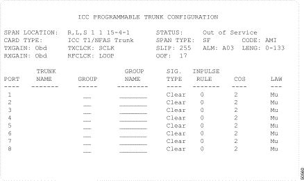
The ICC Programmable Trunk Configuration screen (see Figure 5-3) allows you to configure ICC T1 spans to NFAS groups as ICC T1/NFAS Trunk type spans.
Two fields in the ICC Programmable Trunk Configuration screen are specific to NFAS groups—ALM and SIG. TYPE. These two fields are displayed in the ICC Programmable Trunk Configuration screen only when NFAS groups have been defined. The fields are described in detail below.
ALM—Data entry via Select or Rev Select keys. The ALM field refers to the alarm specification file which determines how the VCO system responds to ICC alarms. The default value is SYS, with an additional selectable value of A03, the recommended value for NFAS groups. You must configure the ALM field, which invokes the alarm specification file, to A03 for NFAS groups.
SIG. TYPE—Data entry via Select or Rev Select, and Enter keys. The SIG. TYPE field determines the signal type in use for the ICC span. Possible values, and their meanings, are as follows:
After you have selected and entered the first port's signal type, Clear, the system software displays the following message at the bottom of your screen:
Press any key to propagate the Clear value to all remaining ports.
Refer to the Cisco VCO/4K System Administrator's Guide for further information on the ICC Programmable Trunk Configuration screen.
The following guidelines assist application designers develop ISDN NFAS applications that make the most efficient use of the system. These are guidelines only, and should not preclude other application design approaches. The guidelines are described in the following sections.
Once NFAS resources (ICC ISDN span and ICC T1 span) are physically inserted in the system equipment frame, use the following steps to add these resources into the system database:
Step 2 Access the ICC ISDN Span Configuration screen through the Card Summary screen and define the operating parameters for the ICC ISDN span. Refer to the "Card Summary Screen" section.
Step 3 Access the ICC Programmable Trunk Configuration screen through the Card Summary screen and define the operating parameters for the ICC T1 spans. The COS must be defined for each T1 port, but the default inpulse rule is not required. Refer to the "ICC Programmable Trunk Configuration Screen" section.
Step 4 Create an NFAS group using the NFAS Group Summary screen.
Step 5 Access the NFAS Group Configuration screen through the NFAS Group Summary screen and add all ICC ISDN span and ICC T1 spans to the interface listing.
To ensure D-channel redundancy, the PRI interfaces must be provisioned identically at both the system and network end. The ICC ISDN span containing the primary D-channel must be connected to the primary (D1) line, while the ICC ISDN span containing the backup D-channel must be connected to the backup (D2) line for the initial contacts and channel switchovers to occur properly. The interface numbering scheme on the NFAS Group Configuration screen can be used for this purpose.
Users may configure different default inpulse rules for the backup D-channel than those set for the primary D-channel. To ensure consistent operation following a switchover, the default inpulse rule for the primary and backup D-channels should be the same.
ICC T1 spans used as NFAS B-channels can interface to 56-KB channels, but actually only support 48-KB transmissions. These channels are suitable for voice traffic only and cannot be used for data. Use ICC ISDN span B-channels for data transmissions.
During a D-channel switchover, some host commands cannot be processed properly because of the slight delay before the backup D-channel is available. These commands are returned with a network status byte of $3D to indicate that the D-channel is not available. Disconnect commands from the host, however, are processed and queued, waiting for the switchover to complete. These commands appear to process normally to the host.
![]()
![]()
![]()
![]()
![]()
![]()
![]()
![]()
Posted: Fri Jan 23 12:18:46 PST 2004
All contents are Copyright © 1992--2004 Cisco Systems, Inc. All rights reserved.
Important Notices and Privacy Statement.