This document provides information on configuring and monitoring the Cisco Easy VPN Remote feature to create IPSec Virtual Private Network (VPN) tunnels between a supported router and an Easy VPN server (Cisco IOS router, VPN 3000 concentrator, or Cisco PIX Firewall) that supports this form of IPSec encryption and decryption.
Feature Specifications for the Cisco Easy VPN Remote
Feature History
Release
Modification
12.2(4)YA
Support for Cisco Easy VPN Remote (Phase I) of this feature was introduced for Cisco 806, Cisco 826, Cisco 827, and Cisco 828 routers; Cisco 1700 series routers; and Cisco uBR905 and Cisco uBR925 cable access routers.
12.2(13)T
Cisco Easy VPN Remote was integrated into Cisco IOS Release 12.2(13)T.
12.2(8)YJ
Support for Cisco Easy VPN Remote (Phase II) of this feature was introduced for Cisco 806, Cisco 826, Cisco 827, and Cisco 828 routers; Cisco 1700 series routers; and Cisco uBR905 and Cisco uBR925 cable access routers.
12.2(15)T
The Cisco Easy VPN Remote feature was integrated into Cisco IOS Release 12.2(15)T. Support for the Cisco 2600 series, Cisco 3600 series, and Cisco 3700 series routers was added.
12.3(2)T
The Type 6 Password in IOS Configuration feature was added.
12.3(4)T
The Save Password and Multiple Peer Backup features were added.
Cable modems, xDSL routers, and other forms of broadband access provide high-performance connections to the Internet, but many applications also require the security of VPN connections that perform a high level of authentication and that encrypt the data between two particular endpoints. However, establishing a VPN connection between two routers can be complicated, and typically requires tedious coordination between network administrators to configure the VPN parameters of the two routers.
The Cisco Easy VPN Remote feature eliminates much of this tedious work by implementing Cisco Unity Client Protocol, which allows most VPN parameters to be defined at a Cisco IOS Easy VPN server. This server can be a dedicated VPN device, such as a Cisco VPN 3000 concentrator or a Cisco PIX Firewall or a Cisco IOS router that supports the Cisco Unity Client Protocol.
After the Cisco Easy VPN server has been configured, a VPN connection can be created with minimal configuration on an Easy VPN remote, such as a Cisco uBR905 or Cisco uBR925 cable access router, a Cisco 800 series router, or a Cisco 1700 series router. When the Easy VPN remote then initiates the VPN tunnel connection, the Cisco Easy VPN server pushes the IPSec policies to the Easy VPN remote and creates the corresponding VPN tunnel connection.
The Cisco Easy VPN Remote feature provides for automatic management of the following details:
Negotiating tunnel parameters, such as addresses, algorithms, and lifetime.
Establishing tunnels according to the parameters.
Automatically creating the Network Address Translation (NAT) or Port Address Translation (PAT) and associated access lists that are needed, if any.
Authenticating users—Making sure that users are who they say they are by way of usernames, group names, and passwords.
Managing security keys for encryption and decryption.
Authenticating, encrypting, and decrypting data through the tunnel.
Modes of Operation
The Cisco Easy VPN Remote feature supports two modes of operation:
Client—Specifies that NAT or PAT be done so that the PCs and other hosts at the client end of the VPN tunnel form a private network that does not use any IP addresses in the IP address space of the destination server.
In client mode, the Cisco Easy VPN Remote feature automatically configures the NAT or PAT translation and access lists that are needed to implement the VPN tunnel. These configurations are automatically created when the IPSec VPN connection is initiated. When the tunnel is torn down, the NAT or PAT and access list configurations are automatically deleted.
The NAT or PAT configuration is created with the following assumptions:
The ip nat inside command is applied to all inside interfaces, including default inside interfaces. The default inside interface is the Ethernet 0 interface (for the Cisco 806, Cisco 826, Cisco 827, Cisco 828, Cisco 831, Cisco 836, and Cisco 837 routers and the Cisco uBR905 and Cisco uBR925 cable access routers).
The ip nat outside command is applied to the interface that is configured with the Cisco Easy VPN Remote configuration. On the Cisco uBR905 and Cisco uBR925 routers, this is always the Cable-modem 0 interface. On the Cisco 800 series and Cisco 1700 series routers, this is the outside interface configured with the Cisco Easy VPN Remote configuration. On the Cisco 1700 series routers, Cisco 2600 series routers, Cisco 3600 series routers, and Cisco 3700 series routers, multiple outside interfaces can be configured.
Tip The NAT or PAT translation and access list configurations that are created by the Cisco Easy VPN Remote feature are not written to either the startup configuration or running configuration files. These configurations, however, can be displayed using the show ip nat statistics and show access-list commands.
Network Extension—Specifies that the PCs and other hosts at the client end of the VPN tunnel should be given IP addresses that are fully routable and reachable by the destination network over the tunneled network so that they form one logical network. PAT is not used, which allows the client PCs and hosts to have direct access to the PCs and hosts at the destination network.
Both modes of operation also optionally support split tunneling, which allows secure access to corporate resources through the VPN tunnel while also allowing Internet access through a connection to an Internet Service Provider (ISP) or other service—thereby eliminating the corporate network from the path for web access.
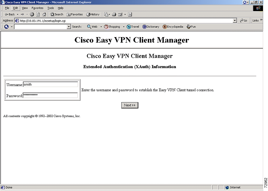
Authentication can also be done using Extended Authentication (Xauth). In this situation, when the Cisco IOS Easy VPN server requests Xauth authentication, the following messages are displayed on the console of the router:
EZVPN: Pending XAuth Request, Please enter the following command:
EZVPN: crypto ipsec client ezvpn xauth
The user can then provide the necessary user ID, password, and other information by entering the crypto ipsec client ezvpn connect command and responding to the prompts that follow.
Note The timeout for entering the username and password is determined by the configuration of the Cisco
IOS Easy VPN server. For servers running Cisco IOS software, this timeout value is specified by the
crypto isakmp xauth timeout command.
Figure 1 illustrates the client mode of operation. In this example, the Cisco uBR905 cable access router provides access to two PCs, which have IP addresses in the 10.0.0.0 private network space. These PCs connect to the Ethernet interface on the Cisco uBR905 router, which also has an IP address in the 10.0.0.0 private network space. The Cisco uBR905 router performs NAT or PAT translation over the VPN tunnel so that the PCs can access the destination network.
Figure 1 Cisco Easy VPN Remote Connection
Note The diagram in Figure 1 could also
represent a split tunneling connection, in which the client PCs can access public resources in the
global Internet without including the corporate network in the path for the public resources.
Figure 2 also illustrates the client mode of operation, in which a VPN concentrator provides destination endpoints to multiple xDSL clients. In this example, Cisco 800 series routers provide access to multiple small business clients, each of which uses IP addresses in the 10.0.0.0 private network space. The Cisco 800 series routers perform NAT or PAT translation over the VPN tunnel so that the PCs can access the destination network.
Figure 3 illustrates the network extension mode of operation. In this example, the Cisco uBR905 cable access router and Cisco 1700 series router both act as Cisco Easy VPN remote devices, connecting to a Cisco VPN 3000 concentrator.
The client hosts are given IP addresses that are fully routable by the destination network over the tunnel. These IP addresses could be either in the same subnet space as the destination network, or they could also be in separate subnets, as long as the destination routers are configured to properly route those IP addresses over the tunnel.
In this example, the PCs and hosts attached to the two routers have IP addresses that are in the same address space as the destination enterprise network. The PCs connect to the Ethernet interface of the Cisco uBR905 router, which also has an IP address in the enterprise address space. This scenario provides a seamless extension of the remote network.
Note For information on configuring the VPN 3000 concentrator for use with the Cisco Easy VPN Remote
feature, see the "Configuring Manual
Tunnel Control" section.
Cisco Easy VPN Remote
The Cisco Easy VPN Remote feature is a collection of features that improves the capabilities of the Cisco Easy VPN Remote feature introduced in Cisco IOS Release 12.2(4)YA. The Cisco Easy VPN Remote feature includes the following:
NAT Interoperability Support—Automatically restores the NAT configuration when the IPSec VPN tunnel is disconnected.
Local Address Support—The Cisco Easy VPN Remote feature is enhanced to support an additional local-address attribute that specifies which interface is used to determine the IP address used to source the Easy VPN tunnel traffic.
Peer Hostname—When a peer is defined as a host name, the host name is stored and the Domain Name System (DNS) lookup is done at time of tunnel connection.
Proxy DNS Server Support—Configures the router in a Cisco Easy VPN Remote configuration to act as a proxy DNS server for LAN-connected users.
Cisco Easy VPN Remote Web Managers—Users can manage the Cisco Easy VPN Remote feature on the Cisco uBR905 and Cisco uBR925 cable access routers using a built-in web interface.
Encrypted Preshared Key—Allows users to securely store plain text passwords in type 6 (encrypted) format in NVRAM.
Save Password—Allows users to save Xauth passwords locally on their PCs so that after the password has been entered initially, the attribute is "pushed" down from the server to the client.
In addition, as part of configuring the Cisco VPN 3000 series concentrator—for the Cisco Easy VPN Remote image—you do not need to create a new IPSec Security Association. Use the default Internet Key Exchange (IKE) and Easy VPN remote lifetime configured on the Cisco VPN 3000 series concentrator.
Manual Tunnel Control
The IPSec Virtual Private Network (VPN) tunnel is automatically connected when the Cisco Easy VPN Remote feature is configured on an interface. If the tunnel times out or fails, the tunnel automatically reconnects and retries indefinitely. Cisco Easy VPN Remote implements manual control of IPSec VPN tunnels so that you can establish and terminate the IPSec VPN tunnel on demand.
The Easy VPN Remote configuration command crypto ipsec client ezvpn name is enhanced with the new subcommand connect [auto | manual] to allow you to specify manual tunnel control.
Automatic is the default setting because it was the initial Cisco Easy VPN Remote functionality. If automatic is the configuration, then you do not need to use the subcommand.
The manual setting means that the Cisco Easy VPN remote will wait for a command before attempting to establish the Cisco Easy VPN Remote connection. When the tunnel times out or fails, subsequent connections will have to wait for the command also.
If the configuration is manual, the tunnel is connected only after you issue the new command, crypto ipsec client ezvpn connect name.
The clear command, clear crypto ipsec client ezvpn [name], is enhanced to disconnect a given tunnel.
The Cisco Easy VPN Remote feature initially supported only one inside interface, which by default was the Fastethernet interface on the Cisco 1700 series and the Ethernet interface on the Cisco 800 series and Cisco uBR900 series.
The inside interface support is enhanced in the Cisco Easy VPN Remote feature to support multiple inside interfaces for all platforms. Inside interfaces can be manually configured with the enhanced command and subcommand:
interface interface-name
crypto ipsec client ezvpn name [outside | inside]
If you want to disable the default inside interface and configure another inside interface on the Cisco uBR905, Cisco uBR925, and on a Cisco 800 series router, you must configure the other inside interface first and then disable the default inside interface. You can use the following command to disable the default inside interface:
no crypto ipsec client ezvpn <name> inside
If you did not configure the other inside interface first before disabling the default inside interface, you receive a message such as the following:
The multiple inside interface enhancements support the following capabilities:
Up to three inside interfaces are supported on the Cisco 1700 and Cisco 800 series routers. The Cisco uBR 925 supports up to only two inside interfaces (Ethernet and USB). The Cisco uBR905 is not affected as it supports only one inside interface (Ethernet).
When multiple tunnels are configured, there can be confusion as to which tunnel gets the default inside interface. The Cisco 1700 series router has no default inside interface, and any inside interface must be configured. The Cisco 800 series and Cisco uBR905 and Cisco uBR925 series cable access routers have default inside interfaces (Ethernet interface). However, any inside interfaces for these platforms can be manually configured and the default inside interface can be disabled.
At least one inside interface must be configured for each outside interface; otherwise, the Cisco Easy VPN Remote feature does not establish a connection.
Adding a new inside interface or removing an existing inside interface automatically resets the Cisco Easy VPN Remote connection (the currently established tunnel). You must reconnect a manually configured tunnel, and if extended authentication (Xauth) is required by the Cisco Easy VPN server, the user is reprompted. If you have set the Cisco Easy VPN Remote configuration to connect automatically and no Xauth is required, no user input is required.
Configuration information for the default inside interface is shown with the show crypto ipsec client ezvpncommand. All inside interfaces, whether they belong to a tunnel, are listed in interface configuration mode as an inside interface, along with the tunnel name.
Multiple Outside Interfaces
The Cisco Easy VPN Client feature initially supported the configuration of only one tunnel for a single outside interface. The Cisco Easy VPN Remote feature adds support for configuration of multiple tunnels for outside interfaces by establishing one tunnel per outside interface. This functionality is applicable to multiple outside interface platforms, such as the Cisco 1700 series routers. The Cisco 800 series routers and the uBR905 and uBR925 cable access routers are not affected because these routers support only one outside interface.
You can configure a maximum of four tunnels. This is done by the enhanced command crypto ipsec client ezvpn nameoutside.
Note Each inside or outside interface supports only one tunnel. Multiple inside interfaces can be mapped to
one outside interface.
To disconnect or clear a specific tunnel, the enhanced command clear crypto ipsec ezvpn name specifies the IPSec VPN tunnel name. If there is no tunnel name specified, all existing tunnels are cleared.
Cisco Easy VPN Remote supports interoperability with Network Address Translation (NAT). You can have a NAT configuration and a Cisco Easy VPN Remote configuration that coexist. When an IPSec VPN tunnel is down, the NAT configuration works.
The Cisco Easy VPN Remote feature automatically creates a NAT configuration, with the corresponding access lists, to implement client mode and split tunneling. In the initial release of the Cisco Easy VPN Remote feature, this automatic NAT and access list configuration overrode any previous NAT and access list configuration. When a tunnel timed out or disconnected—due to manual tunnel control, for example—the automatic NAT and access configuration was automatically removed, which prevented any Internet access even to non-tunnel destinations.
In the Cisco Easy VPN Remote feature, the router automatically restores the previous NAT configuration when the IPSec VPN tunnel is torn down. The user-defined access lists are not disturbed. Users can continue to access non-tunnel areas of the Internet when the tunnel times out or disconnects.
Local Address Support
The Cisco Easy VPN Remote feature is enhanced to support an additional local-address attribute that specifies which interface is used to determine the IP address used to source the Easy VPN Remote tunnel traffic. After specifying the interface with the local-address subcommand, you can manually assign a static IP address to the interface or use the cable-modem dhcp-proxy interface command to automatically configure the specified interface with a public IP address. See the "Configuring Proxy DNS Server Support" section for configuration information. See the "Cable DHCP Proxy Enhancement Configuration Examples" section for more information on the cable-modem dhcp-proxy interface command.
The local-address support is available for all platforms, but it is more applicable to the Cisco uBR905 and Cisco uBR925 cable access routers in conjunction with the cable-modem dhcp-proxy interface command. Typically, the loopback interface is the interface used to source tunnel traffic for the Cisco uBR905 and Cisco uBR925 cable access routers.
In a typical DOCSIS network, the Cisco uBR905 and Cisco uBR925 cable access routers are normally configured with a private IP address on the cable-modem interface. In the initial Cisco Easy VPN Remote feature, a public IP address was required on the cable-modem interface to support the Easy VPN remote.
In the Cisco Easy VPN Remote feature, cable providers can use the Cable DHCP Proxy feature to obtain a public IP address and assign it to the cable modem interface, which is usually the loopback interface.
To support the Cisco Easy VPN Remote feature on the uBR905 and uBR925 cable access routers, the existing cable-modem dhcp-proxy interface configuration command is enhanced to support the loopback interface. The router automatically configures the loopback interface with the public IP address obtained from the DHCP server. You must create the loopback interface, which is a virtual interface, first before issuing the cable-modem dhcp-proxy interface command.
Note The cable-modem dhcp-proxy interface command is supported only for the Cisco uBR905 and
Cisco uBR925 cable access routers.
Peer Hostname
The peer in a Cisco Easy VPN Remote feature configuration can be defined as an IP address or a hostname. Typically when a peer is defined as a hostname, a Domain Name System (DNS) lookup is done immediately to get an IP address. In the Cisco Easy VPN Remote feature, the peer hostname operation is enhanced to support DNS entry changes. The text string of the hostname is stored so that the DNS lookup is done at the time of the tunnel connection, not when the peer is defined as a hostname.
When the WAN connection is down—that is, the IPSec VPN tunnel is down—the Domain Name System (DNS) addresses of the ISP or cable provider should be used to resolve DNS requests. When the WAN connection is up, the DNS addresses of the enterprise should be used.
As a way of implementing use of the DNS addresses of the cable provider when the WAN connection is down, the router in a Cisco Easy VPN Remote configuration can be configured to act as a proxy DNS server. The router, acting as a proxy DNS server for LAN-connected users, receives DNS queries from local users on behalf of the real DNS server. The Dynamic Host Configuration Protocol (DHCP) server then is able to send out the LAN address of the router as the IP address of the DNS server. Then after the WAN connection comes up, the router forwards the DNS queries to the real DNS server and caches the DNS query records.
The Cisco Easy VPN Remote feature works in conjunction with Cisco IOS Firewall configurations on all platforms.
Simultaneous Easy VPN Remote and Server
You can configure simultaneous Cisco Easy VPN remote and Cisco Easy VPN server support on the same Cisco 1700 series routers. You can configure one outside interface as a Cisco Easy VPN server and another outside interface on the same router as a Cisco Easy VPN remote device. This support is applicable for multiple outside interface platforms, such as the Cisco 1700 series routers, Cisco 2600 series routers, Cisco 3600 series routers, and Cisco 3700 series routers.
Note The Easy VPN remote and Easy VPN server configuration cannot be on the same interface.
Cisco Easy VPN Remote Web Managers
Web interface managers may be used to manage the Cisco Easy VPN Remote feature. One such web interface manager is Security Device Manager (SDM), which is supported on the Cisco 830 series, Cisco 1700 series, Cisco 2600 series, Cisco 3600 series, and Cisco 3700 series routers. SDM enables you to connect or disconnect the tunnel and provides a web interface for Xauth. For more information about SDM, refer to Cisco Security Device Manager .
Another web interface manager is the Cisco Router Web Setup (CRWS) tool, which is supported on the Cisco 806 router. The CRWS provides a similar web interface as SDM.
A third web interface manager, Cisco Easy VPN Remote Web Manager, is used to manage the Cisco Easy VPN Remote feature for Cisco uBR905 and Cisco uBR925 cable access routers. You do not need access to the command-line interface (CLI) to manage the Cisco Easy VPN remote connection.
The web interface managers allow you to do the following:
See the current status of the Cisco Easy VPN remote tunnel.
Connect a tunnel that is configured for manual control.
Disconnect a tunnel that is configured for manual control or reset a tunnel configured for automatic connection.
Be prompted for Xauth information if Xauth information is needed.
The Encrypted Preshared Key feature allows you to securely store plain text passwords in type 6 (encrypted) format in NVRAM.
For information about the Encrypted Preshared Key feature, refer to the following document:
Encrypted Preshared Key feature module for Cisco IOS Release 12.3(2)T
Save Password
The Save Password feature allows the Xauth username and password to be saved in the Easy VPN Remote configuration so that you are not required to enter the username and password manually. One time Password (OTP) schemes are not supported and must be entered manually every time. The Easy VPN server must be configured to "Allow Saved Passwords," and the remote router will issue a message to unconfigure any saved usernames and passwords if the server does not allow saved passwords.
To configure the Save Password feature on the remote, use the username subcommand of the crypto ipsec client ezvpn command in global configuration mode.
If encryption of the saved password in the running configuration is required, the following two commands have to be issued before the password is configured: password encryption aes and key config-key password-encryption.
Multiple Peer Support for Dead Peer Detection Stateless Failover
The Multiple Peer Support for Dead Peer Detection Stateless Failover feature allows users to enter multiple peer statements. With this feature configured, if the client is connecting to a peer and the negotiation fails, Easy VPN fails over to the next peer. This failover continues through the list of peers. When the last peer is reached, Easy VPN rolls over to the first peer. The IKE and IPSec security associations (SAs) to the previous peer are deleted. Multiple peer statements work for both IP addresses as well as for host names. Setting or unsetting the peer statements will not affect the order of the peer statements.
To use this feature, use the peer subcommand of the crypto ipsec client ezvpn command.
Benefits
Allows dynamic configuration of end-user policy, requiring less manual configuration by end users and field technicians, thus reducing errors and further service calls.
Allows the provider to change equipment and network configurations as needed, with little or no reconfiguration of the end-user equipment.
Provides for centralized security policy management.
Enables large-scale deployments with rapid user provisioning.
Eliminates the need for end users to purchase and configure external VPN devices.
Eliminates the need for end users to install and configure Easy VPN Client software on their PCs.
Offloads the creation and maintenance of the VPN connections from the PC to the router.
Reduces interoperability problems between the different PC-based software VPN clients, external hardware-based VPN solutions, and other VPN applications.
Restrictions
Subinterfaces Not Supported
Establishing Cisco Easy VPN Remote tunnels over subinterfaces is not supported in Cisco IOS Releases 12.2(15)T, 12.3(2)T, or 12.3(4)T.
Cisco Easy VPN Remote Web Manager Does Not Support Cable-Monitor Web Interface
The Cisco Easy VPN Remote Web Manager does not work with the cable monitor web interface in Cisco IOS Releases 12.2(15)T, 12.3(2)T, or 12.3(4)T. To access the cable monitor web interface, you must first disable the Cisco Easy VPN Remote web interface with the no ip http ezvpn command, and then enable the Cable Monitor with the ip http cable-monitor command.
Required Easy VPN Servers
The Cisco Easy VPN Remote feature requires that the destination peer be a Cisco IOS Easy VPN server or VPN concentrator that supports the Cisco Easy VPN Server feature. At the time of publication, this includes the following platforms when running the indicated software releases:
Cisco 806, Cisco 826, Cisco 827, Cisco 828, Cisco 831, Cisco 836, and Cisco 837 routers—Cisco IOS Release 12.2(8)T or later release
Cisco 1700 series—Cisco IOS Release 12.2(8)T or later release
Cisco 2600 series—Cisco IOS Release 12.2(8)T or later release
Cisco 3620—Cisco IOS Release 12.2(8)T or later release
Cisco 3640—Cisco IOS Release 12.2(8)T or later release
Cisco 3660—Cisco IOS Release 12.2(8)T or later release
Cisco 7100 series VPN routers—Cisco IOS Release 12.2(8)T or later release
Cisco 7200 series routers—Cisco IOS Release 12.2(8)T or later release
Cisco 7500 series routers—Cisco IOS Release 12.2(8)T or later release
Cisco uBR905 and Cisco uBR925 cable access routers—Cisco IOS Release 12.2(8)T or later release
Cisco VPN 3000 series—Software Release 3.11 or later release
Cisco PIX 500 series—Software Release 6.2 or later release
Digital Certificates Not Supported
In Cisco IOS Release 12.2(15)T, 12.3(2)T, and 12.3(4)T, the Cisco Easy VPN Remote feature does not support authentication using digital certificates. Authentication is supported using preshared keys and Xauth.
Only ISAKMP Policy Group 2 Supported on Easy VPN Servers
The Unity Protocol supports only Internet Security Association Key Management Protocol (ISAKMP) policies that use group 2 (1024-bit Diffie-Hellman) IKE negotiation, so the Easy VPN server being used with the Cisco Easy VPN Remote feature must be configured for a group 2 ISAKMP policy. The Easy VPN server cannot be configured for ISAKMP group 1 or group 5 when being used with a Cisco Easy VPN client.
Perfect Forward Secrecy Not Supported
The Cisco Easy VPN Remote feature does not support the Perfect Forward Secrecy (PFS) feature that is available on the Cisco VPN 3000 concentrator.
Transform Sets Supported
To ensure a secure tunnel connection, the Cisco Easy VPN Remote feature does not support transform sets that provide encryption without authentication (ESP-DES and ESP-3DES) or transform sets that provide authentication without encryption (ESP-NULL ESP-SHA-HMAC and ESP-NULL ESP-MD5-HMAC).
Note The Cisco Unity Client Protocol does not support Authentication Header (AH) authentication, but
Encapsulation Security Protocol (ESP) is supported.
Changing the IP Address on the LAN Interface on Cisco 800 Series Routers
The Ethernet 0 LAN interface on the Cisco 800 series routers defaults to a primary IP address in the private network of 10.10.10.0. You can change this IP address to match the configuration of the local network by using either the ip address command or the CRWS web interface.
These two techniques differ slightly in how the new IP address is assigned. When the CLI command is used, the new IP address is assigned as the primary address for the interface. When the CRWS interface is used, the new IP address is assigned as the secondary address and the existing IP address is preserved as the primary address for the interface. This allows the CRWS interface to maintain the existing connection between the PC web browser and the Cisco 800 series router.
Because of this behavior, the Cisco Easy VPN Remote feature assumes that if a secondary IP address exists on the Ethernet 0 interface, the secondary address should be used as the IP address for the inside interface for the NAT or PAT configuration. If no secondary address exists, the primary IP address is used for the inside interface address, as is normally done on other platforms. If this behavior is not desired, use the ip address command to change the address of the interface, instead of using the CRWS web interface.
VPN 3000 Configuration
The configuration of the Cisco VPN 3000 concentrator has some restrictions when used with the Cisco Easy VPN Remote feature. See the "Configuring Manual Tunnel Control" section for more details.
Cisco 2600 Series, 3600 Series, and 3700 Series Regulatory Compliance and Safety Information on the Cisco.com website.
IPsec and VPN Documentation
For information on the Easy VPN Server feature, which provides Cisco Unity client support for the Cisco Easy VPN Remote feature, see Easy VPN Server for Cisco IOS Release 12.2(8)T.
For general information on IPSec and VPN subjects, see the following information in the product literature and IP technical tips sections on Cisco.com :
Deploying IPsec —Provides an overview of IPsec encryption and its key concepts, along with sample configurations. Also provides a link to many other documents on related topics.
The following technical documents, available on Cisco.com and the Documentation CD-ROM, also provide more in-depth configuration information:
IPSec VPN (under the "Technical Documents" and "Cisco IOS IPSec Configuration Documents" sections)—Provides examples for configuring Cisco IOS Easy VPN in client mode and in network extension mode.
Cisco Easy VPN Solutions —Provides white papers and examples for configuring Cisco IOS Easy VPN in network extension mode.
Cisco IOS Security Command Reference , Cisco IOS Release 12.3 T—Provides a reference for each of the Cisco IOS commands used to configure IPsec encryption and related security features.
Cisco IOS Master Commands List, Release 12.3—Summarizes the Cisco IOS commands used to configure all Release 12.1 security features.
Note Additional documentation on IPSec becomes available on
Cisco.com and the Documentation CD-ROM as
new features and platforms are added. Cisco Press also publishes several books on IPSec—go to
http://www.ciscopress.com for more
information on Cisco Press books.
Determining Platform Support Through Feature Navigator
Use Cisco Feature Navigator to find information about platform support and Cisco IOS software image support. Access Cisco Feature Navigator at http://www.cisco.com/go/fn . You must have an account on Cisco.com. If you do not have an account or have forgotten your username or password, click Cancel at the login dialog box and follow the instructions that appear.
Supported Standards, MIBs, and RFCs
Standards
No new or modified standards are supported by this feature.
MIBs
The following new or modified MIBs are supported by this feature:
CISCO-IPSEC-FLOW-MONITOR-MIB—Contains attributes describing IPSec-based VPNs (Internet Engineering Task Force (IETF) IPSec Working Group Draft).
CISCO-IPSEC-MIB—Describes Cisco implementation-specific attributes for Cisco routers implementing IPSec VPNs.
CISCO-IPSEC-POLICY-MAP-MIB—Extends the CISCO-IPSEC-FLOW-MONITOR-MIB to map dynamically instantiated structures to the policies, transforms, cryptomaps, and other structures that created or are using them.
To obtain lists of supported MIBs by platform and Cisco IOS release, and to download MIB modules, go to the Cisco MIB website on Cisco.com at the following URL:
No new or modified RFCs are supported by this feature.
Prerequisites
The following requirements are necessary to use the Cisco Easy VPN Remote feature:
A Cisco 800 series router; Cisco 1700 series router; or Cisco uBR905 or Cisco uBR925 cable access router running Cisco IOS Release 12.2(15)T, 12.3(2)T, and 12.3(4)T or later, configured as a Cisco Easy VPN Client.
Another Cisco router or VPN concentrator that supports the Cisco Easy VPN Server feature and that is configured as a Cisco IOS Easy VPN server. See the "Required Easy VPN Servers" section for a detailed list.
Configuration Tasks
See the following sections for configuration tasks for the Cisco Easy VPN Remote feature. The tasks are listed under the subsections Remote Tasks, Easy VPN Server Tasks, and Web Interface Tasks. Each task is identified as either required or optional.
Configuring and Assigning the Cisco Easy VPN Remote Configuration
The router acting as the Easy VPN remote must create a Cisco Easy VPN Remote configuration and assign it to the outgoing interface. To do so, use the following commands beginning in global configuration mode.
Command
Purpose
Step 1
Router(config)# crypto ipsec client ezvpn
name
Creates an remote configuration named name and enters Cisco Easy VPN Remote configuration mode.
Step 2
Router(config-crypto-ezvpn)# group
group-namekey group-key
Specifies the IPSec group and IPSec key value to be associated with this configuration.
Note The value of group-name must match the group defined on the IPSec server. On Cisco IOS routers, use the crypto isakmp client configuration group and crypto map dynmap isakmp authorization list commands.
Note The value of group-key must match the key defined on the IPSec server. On Cisco IOS routers, use the crypto isakmp client configuration group command.
Specifies the type of VPN connection that should be made:
client—Specifies that the router is configured for VPN client operation, using NAT or PAT address translation.
network-extension—Specifies that the router is to become a remote extension of the enterprise network at the destination of the VPN connection.
Step 5
Router(config-crypto-ezvpn)# exit
Exits Cisco Easy VPN Remote configuration mode.
Step 6
Router(config)# interface interface
Enters interface configuration mode for the interface. This interface will become the outside interface for the NAT or PAT translation.
Step 7
Router(config-if)# crypto ipsec client
ezvpn name [outside]
Assigns the Cisco Easy VPN Remote configuration to the interface. This automatically creates the necessary NAT or PAT translation parameters and initiates the VPN connection.
Note You can assign the Cisco Easy VPN Remote configuration to only one interface. You cannot assign the configuration to the interface that defaults to being the "inside" interface for the NAT or PAT translation. On Cisco 1700 series routers, this is the FastEthernet 0 interface. On Cisco 800 series routers, this could be either the Ethernet 0 or Dialer 1 interface, depending on which is applicable. On Cisco uBR905 and Cisco uBR925 cable access routers, this is the Ethernet 0 interface.
Step 8
Router(config-if)# exit
Exits interface configuration mode.
Step 9
Router(config)# exit
Exits global configuration mode.
Verifying the Cisco Easy VPN Configuration
To verify that the Cisco Easy VPN remote configuration has been correctly configured, that the configuration has been assigned to an interface, and that the IPSec VPN tunnel has been established, use the following commands:
Step 1 Display the current state of the Cisco Easy VPN Remote connection using the show crypto ipsec client ezvpn command. The following is typical output for a Cisco 1700 series router using client mode:
The following is typical output for a router using network extension mode:
Router# show crypto ipsec client ezvpn
Current State: IPSEC_ACTIVE
Last Event: SOCKET_UP
Address: 10.30.0.53
Mask: 255.255.255.255
Split Tunnel List: 1
Address : 10.300.0.0
Mask : 255.255.255.128
Protocol : 0x0
Source Port: 0
Dest Port : 0
Step 2 Display the NAT or PAT configuration that was automatically created for the VPN connection using the show ip nat statistics command. The "Dynamic mappings" field of this display gives the details for the NAT or PAT translation that is occurring on the VPN tunnel.
Router# show ip nat statistics
Total active translations: 0 (0 static, 0 dynamic; 0 extended)
Outside interfaces:
cable-modem0
Inside interfaces:
Ethernet0
Hits: 1489 Misses: 1
Expired translations: 1
Dynamic mappings:
-- Inside Source
access-list 198 pool enterprise refcount 0
pool enterprise: netmask 255.255.255.0
start 192.1.1.90 end 192.1.1.90
type generic, total addresses 1, allocated 0 (0%), misses 0\
Router#
Step 3 In client mode, the NAT or PAT translation creates one or more access lists that are also dynamically configured at the time the VPN tunnel is initiated. Display this access list using the show access-list command. The following is a typical display for a client configuration without split tunneling:
Router# show access-list
Extended IP access list 198
permit ip 192.1.1.0 0.0.0.255 any
Router#
Note In this example, the Cisco Easy VPN Remote configuration creates access list 198 for the
VPN tunnel NAT or PAT translation. The exact numbering of the access list can vary,
depending on the other access lists that have been configured on the router. Do not
assume that the VPN tunnel will use the same access list every time the connection is
initiated.
The following is a typical display for a Cisco uBR905 or a Cisco uBR925 cable access router configured for client mode with split tunneling:
Router# show access-list
Extended IP access list 197
deny ip 192.168.100.0 0.0.0.255 172.168.0.128 0.0.0.127
deny ip 192.168.100.0 0.0.0.255 172.168.1.128 0.0.0.127
permit ip 192.168.100.0 0.0.0.255 any
Extended IP access list 198
permit ip 192.168.100.0 0.0.0.255 172.168.0.128 0.0.0.127
permit ip 192.168.100.0 0.0.0.255 172.168.1.128 0.0.0.127
Router#
Tip Network extension mode without split tunneling does not need any access lists and thus does not create them. Network extension mode with split tunneling typically creates a single access list.
The following is a typical display for a Cisco 827 router configured for client mode with split tunneling:
Router# show access-list
Extended IP access list 197
deny ip 70.0.0.0 0.255.255.255 30.100.0.0 0.0.0.127 (5 matches)
permit ip 70.0.0.0 0.255.255.255 any
Extended IP access list 198
permit ip 70.0.0.0 0.255.255.255 30.100.0.0 0.0.0.127 (5 matches)
Step 4 Display the destination IPSec peer and the key value being used with the show crypto isakmp key command:
Router# show crypto isakmp key
Hostname/Address Preshared Key
192.1.1.1 hw-client-password
Router#
Configuring Save Password
To configure the Save Password feature, perform the following procedure beginning in global configuration mode.
Command
Purpose
Step 1
Router(config)# crypto ipsec client
ezvpnname
Creates a Cisco Easy VPN remote configuration and enters the Cisco Easy VPN remote configuration mode.
Allows you to save your Xauth password locally on the PC.
The 0 keyword specifies that an unencrypted password will follow.
The 6 keyword specifies that an encrypted password will follow.
The password argument is the unencrypted (cleartext) user password.
Step 5
Router (config-crypto-ezvpn)# exit
Exits the Cisco Easy VPN remote configuration mode.
Step 6
Router (config)# show running-config
Displays the contents of the currently running configuration file.
Configuring Dead Peer Detention
To configure dead peer support, perform the following procedure beginning in global configuration mode. This procedure must be done before multiple peer support can be configured.
Sends dead peer detection (DPD) messages to the router.
Configuring Manual Tunnel Control
To configure control of IPSec VPN tunnels manually so that you can establish and terminate the IPSec VPN tunnels on demand, use the following procedure beginning in global configuration mode.
Note CLI is one option for connecting the tunnel. The preferred method is via the web interface (using
SDM).
Command
Purpose
Step 1
Router(config)# crypto ipsec client ezvpnname
Assigns a Cisco Easy VPN remote configuration to an interface and enters Cisco Easy VPN Remote configuration mode. Specify the configuration name to be assigned to the interface.
Connects the VPN tunnel. Specify manual to configure manual tunnel control. Automatic is the default; you do not need to use this subcommand if your configuration is automatic.
Step 3
Router(config-crypto-ezvpn)# exit
Exits Cisco Easy VPN Remote configuration mode.
Step 4
Router(config)# exit
Exits global configuration mode and enters privileged EXEC mode.
Step 5
Router#crypto ipsec client ezvpn connectname
Connects a given Cisco Easy VPN remote configuration. Specify the IPSec VPN tunnel name.
Note If the tunnel name is not specified, the active tunnel is
connected. If there is more than one active tunnel, the
command fails with an error requesting that you
specify the tunnel name.
Step 6
Router# clear crypto ipsec client ezvpn
[name]
(Optional) Disconnects a given Cisco Easy VPN remote configuration. If the IPSec VPN tunnel name is specified, then that tunnel only is cleared. If no tunnel name is specified, then all active tunnels are cleared.
Note If the tunnel name is not specified, the active tunnel is
disconnected. If there is more than one active tunnel,
the command fails with an error requesting that you
specify the tunnel name.
Configuring Automatic Tunnel Control
This configuration is the same as the "Configuring Manual Tunnel Control" configuration except that in Step 2, the auto keyword should be used.
Configuring Multiple Inside Interfaces
You can configure up to three inside interfaces for all platforms. You need to manually configure each inside interface with the following procedure:
Command
Purpose
Step 1
Router(config-if)# interfaceinterface-name1
Selects the interface you want to configure by specifying the interface name.
Specifies the Cisco Easy VPN remote configuration name to be assigned to the first inside interface. You must specify inside for each inside interface.
Step 3
Router(config-if)# interfaceinterface-name2
Selects the next interface you want to configure by specifying the next interface name.
Specifies the Cisco Easy VPN remote configuration name to be assigned to the next inside interface. You must specify inside for each inside interface.
Repeat step 3 through step 4 to configure an additional tunnel if desired.
Configuring Multiple Outside Interfaces
You can configure multiple tunnels for outside interfaces, setting up a tunnel for each outside interface. You can configure a maximum of four tunnels using the following procedure for each outside interface:
Command
Purpose
Step 1
Router(config-if)# interfaceinterface-name1
Selects the first outside interface you want to configure by specifying the interface name.
Specifies the Cisco Easy VPN remote configuration name to be assigned to the first outside interface. Specify outside (optional) for each outside interface.
If neither outside nor inside is specified for the interface, the default is outside.
Step 3
Router(config-if)#interface
interface-name2
Selects the next outside interface you want to configure by specifying the next interface name.
Specifies the Cisco Easy VPN remote configuration name to be assigned to the next outside interface. Specify outside (optional) for each outside interface.
If neither outside nor inside is specified for the interface, the default is outside.
Repeat step 3 through step 4 to configure additional tunnels if desired.
Configuring Proxy DNS Server Support
As a way of implementing the use of the DNS addresses of the cable provider when the WAN connection is down, the router in a Cisco Easy VPN remote configuration can be configured to act as a proxy DNS server. To enable the proxy DNS server functionality with the ip dns server command, use the following commands beginning in global configuration mode.
Command
Purpose
Step 1
Router(config)# ip dns server
Enables the router to act as a proxy DNS server.
Note This definition is IOS specific.
After configuring the router, you configure the Cisco IOS Easy VPN server as follows:
Under the crypto isakmp client configuration groupgroupname
dnsA.B.C.D A1.B1.C1.D1
These DNS server addresses should be pushed from the server to the Cisco Easy VPN remote and dynamically added to or deleted from the running configuration of the router.
The local router uses DHCP to assign IP addresses to the PCs that are connected to the LAN interface of the router. This requires creating a pool of IP addresses for the onboard DHCP server of the router. The DHCP server then assigns an IP address from this pool to each PC when it connects to the router.
In a typical VPN connection, the PCs connected to the LAN interface of the router are assigned an IP address in a private address space. The router then uses NAT or PAT to translate those IP addresses into a single IP address that is transmitted across the VPN tunnel connection.
Tip Configuring the DHCP server pool is not normally needed on the Cisco 800 series routers because this is automatically done when using the SDM or CRWS web interface that is available on those routers. Also, the DHCP server pool is not normally needed if using a router, such as the Cisco 827, with an ATM interface configured for PPPoE connections.
To configure the DHCP server pool on the Cisco uBR905 and Cisco uBR925 cable access routers and the Cisco 1700 series routers, use the following commands beginning in global configuration mode.
Command
Purpose
Step 1
Router(config)# ip dhcp poolpool-name
Creates a DHCP server address pool named pool-name and enters DHCP pool configuration mode.
Specifies the IP network number and subnet mask of the DHCP address pool that is to be used for the PCs connected to the local Ethernet interface of the router. This network number and subnet mask must specify the same subnet as the IP address assigned to the Ethernet interface.
The subnet mask can also be specified as a prefix length that specifies the number of bits in the address portion of the subnet address. The prefix length must be preceded by a forward slash (/).
Specifies the IP address of the default router for a DHCP client. You must specify at least one address. You can optionally specify additional addresses, up to a total of eight addresses per command.
Tip The first IP address for the default-router option should be the IP address that is assigned to the Ethernet address of the router.
Step 4
Router(dhcp-config)# import all
Imports the following DHCP option parameters from a central DHCP server into the local DHCP database of the router:
Domain Name
DNS server
NetBIOS WINS server
Note This option requires that a central DHCP server be configured to provide the DHCP options. The central DHCP server should be on the same subnet that was configured using the network option. (On Cisco IOS routers, this is done using the ip dhcp database command.) If you are using the Point-to-Point Protocol (PPP) or IP Control Protocol (IPCP) on the outside interface, or the client on the outside interface supports the Cisco Easy IP feature, the central DHCP server can be on a different subnet or network.
Note You can also specify the DHCP option parameters manually by using the domain-name, dns-server, and netbios-name-server keywords, but this is not recommended. Almost all installations should use the import all option to ensure that the router is configured with the proper DHCP parameters.
Step 5
Router(dhcp-config)# lease {days
[hours][minutes] | infinite}
(Optional) Specifies the duration of the DHCP lease. The default is a one-day lease.
Step 6
Router(dhcp-config)# exit
Leaves DHCP pool configuration mode.
Step 7
Router(config)# ip dhcp excluded-addresslan-ip-address
Excludes the specified IP address from the DHCP server pool. The lan-ip-address should be the IP address assigned to the LAN interface of the router (for example, the Ethernet 0 on Cisco uBR905 and Cisco uBR925 routers and FastEthernet 0 on Cisco 1700 series routers).
Note The ip dhcp pool command supports a number of options for configuring the DHCP server pool.
These other options are typically not needed for a Cisco Easy VPN remote configuration.
Verifying the DHCP Server Pool
To verify that the DHCP server pool has been correctly configured, use the following commands:
Step 1 Use the show ip dhcp pool command in privileged EXEC mode to display the server pools that have been created:
Router# show ip dhcp pool
Pool localpool :
Current index : 192.168.100.1
Address range : 192.168.100.1 - 192.168.100.254
Router#
Step 2 If you used the import all option when you created the DHCP server pool, use the show ip dhcp import command to display the options that have been imported from the central DHCP server:
Router# show ip dhcp import
Address Pool Name: localpool
Domain Name Server(s): 192.168.20.5
NetBIOS Name Server(s): 192.168.20.6
Domain Name Option: cisco.com
Router#
Step 3 To display the IP addresses that the DHCP server has assigned, use the show ip dhcp binding command:
Router# show ip dhcp binding
IP address Hardware address Lease expiration Type
192.168.100.3 00c0.abcd.32de Nov 01 2001 12:00 AM Automatic
192.168.100.5 00c0.abcd.331a Nov 01 2001 12:00 AM Automatic
Router#
Troubleshooting Tips
If PCs connected to the LAN interface of the router cannot obtain an IP address using DHCP, check the following:
Verify that the DHCP server has not been disabled on the router. The DHCP server is enabled by default, but it might have been disabled using the no service dhcp command. To check this, use the show running-config command:
Router# show running-config | include dhcp
no service dhcp
ip dhcp pool localpool
Router#
If the output from the show running-config command does not include the no service dhcp command, the DHCP server is enabled.
Use the show ip dhcp binding command to display the IP addresses that have already been assigned. Verify that the address pool has not been exhausted. If necessary, recreate the pool to create a larger pool of addresses.
On a Windows PC that is connected to the LAN interface of the router, use the ipconfig /all command to display its IP address configuration, including the DHCP server address:
Configuring the Cisco VPN 3000 Series Concentrator
This section describes the guidelines required to configure the Cisco VPN 3000 series concentrator for use with the Cisco Easy VPN Remote feature. As a general rule, you can use the default configuration except for IP addresses, server addresses, and routing configurations and for the following parameters and options:
Note You must be using Cisco VPN 3000 series concentrator software release 3.11 or later to support
Cisco Easy VPN Clients and remotes.
When you have configured the Cisco Easy VPN server configuration on the VPN 3000 concentrator to use hostname as its identity, then you must configure the peer on the Cisco Easy VPN remote using hostname. You can either configure DNS on the client to resolve the peer hostname, or you can configure peer hostname locally on the client using the ip host peer_hostname ip_address command. As an example, you can configure the peer host name locally on an Easy VPN remote with the ip host crypto-gw.cisco.com 10.0.0.1 command. Or you can configure the Easy VPN remote to use the host name with the peer hostname command, such as peer crypto-gw.cisco.com.
The Interactive Hardware Client Authentication Version 3.5—The Cisco Easy VPN Remote feature does not support the Interactive Hardware Client Authentication Version 3.5 feature. This feature must be disabled. This is configured on the VPN 3000 series concentrator by clicking the HW Clienttab on the Configuration | User Management | Base Group screen.
IPSec Tunnel Protocol—Enables the IPSec tunnel protocol so that it is available for users. This is configured on the Cisco VPN 3000 series concentrator by clicking the General tab on the Configuration | User Management | Base Group screen.
IPSec group—Configures the Cisco VPN 3000 series concentrator with a group name and password that match the values configured for the Cisco Easy VPN remote configuration on the router. These values are configured on the router with the groupgroup-namekeygroup-key command and are configured on the Cisco VPN 3000 series concentrator using the Configuration | User Management | Groupsscreen.
Perfect Forward Secrecy—The Cisco Easy VPN Remote feature does not support the PFS option. This option must be set to Disabled in the Configuration | Policy Management | Traffic Management | Security Associations screens.
Group Lock—If you are defining multiple users in multiple groups on the VPN 3000 series concentrator, you must check the Group Lock box in the IPSec tab to prevent users in one group from logging in with the parameters of another group. For example, if you have configured one group for split tunneling access and another group without split tunneling access, clicking the Group Lock box prevents users in the second group from gaining access to the split tunneling features. The Group Lock checkbox appears in the IPSec tab in the Configuration | User Management | Base Groupscreen and in the IPSec tab in the Configuration | User Management | Groups | Add/Modifyscreens.
Xauth—To use Xauth, set the Authentication parameter to None. The Authentication parameter appears in the IPSec tab in the Configuration | User Management | Base Groupscreen and in the IPSec tab in the Configuration | User Management | Groups | Add/Modifyscreens.
Split Tunneling—The Configuration | User Management | Base Group, Mode Configuration Parameters Tab screen includes a Split Tunnel option with a checkbox that says "Allow the networks in the list to bypass the tunnel."
IKE Proposals—The Cisco VPN 3000 series concentrator is preconfigured with a default IKE proposal, CiscoVPNClient-3DES-MD5, that can be used with Cisco Easy VPN remotes. This IKE proposal supports preshared keys with Xauth using the MD5/HMAC-128 algorithm and Diffie-Hellman Group 2.
This proposal is active by default, but verify that it is still an active proposal using the Configuration | System | Tunneling Protocols | IPSec | IKE Proposals screen.
Note You can also use the default IKE proposals IKE-DES-MD5 and IKE-3DES-MD5, but
they do not enable XAUTH support by default.
Create a new IPSec Security Association. Cisco Easy VPN Clients use a security association with the following parameters:
Authentication Algorithm=ESP/MD5/HMAC-128
Encryption Algorithm=DES-56 or 3DES-168 (recommended)
Encapsulation Mode=Tunnel
Digital Certificate=None (use preshared keys)
IKE Proposal=CiscoVPNClient-3DES-MD5 (preferred)
The Cisco VPN 3000 series concentrator is preconfigured with several default security associations, but they do not meet the IKE proposal requirements. To use an IKE proposal of CiscoVPNClient-3DES-MD5, copy the ESP/IKE-3DES-MD5 security association and modify it to use CiscoVPNClient-3DES-MD5 as its IKE proposal. This is configured on the VPN 3000 series concentrator using the Configuration | Policy Management | Traffic Management | Security Associationsscreen.
Configuring an Easy VPN Server on a PIX Firewall
For information about configuring an Easy VPN Server on a PIX Firewall, refer to the following document:
Configuring and Using the Cisco Easy VPN Remote Web Manager
To configure and use the Cisco Easy VPN Remote Web Manager for the Cisco uBR905 and Cisco uBR925 cable access routers, follow these steps:
1. Enter configuration information in the IOS configuration file to enable the Hypertext Transfer Protocol (HTTP) web server and the Cisco Easy VPN remote part of the HTTP server, in global configuration mode as follows:
Command
Purpose
Step 1
Router# configure terminal
Enters global configuration mode.
Step 2
Router(config)# ip http server
To enable an HTTP server on your system and allow use of the Cisco Web browser user interface to monitor the router and issue commands to it.
Step 3
Router(config)# ip http authentication
{aaa|enable|local|tacacs}
To set up an HTTP authentication method for HTTP server users to access the Cisco Easy VPN Remote Web Manager, select one of the following:
aaa—Indicates that the AAA facility is used for authentication.
enable—Indicates that the enable password method is used for authentication. This is the default method of HTTP server user authentication and authenticates at privilege level 15. If there is no enable password, no authentication is prompted.
local—Indicates that the local user database as defined on the Cisco router or access server is used for authentication. Allows you to tailor a password without revealing the enable password to the end user. This method is preferred to authenticate the Cisco Easy VPN Remote Web Manager.
tacacs—Indicates that the Terminal Access Controller Access Control System+ (TACACS) or Extended TACACS (XTACACS) server is used for authentication.
Step 4
Router(config)# ip http ezvpn
Enables the Cisco Easy VPN Remote feature on the HTTP server.
See "Command Reference" for an example of selecting the local method of authentication.
Note The Cisco Easy VPN Remote Web Manager does not work with the cable monitor web
interface in Cisco IOS Release 12.2(15)T. To access the cable monitor web interface, you
must first disable the Cisco Easy VPN remote web interface with the no ip http ezvpn
command, and then enable the cable monitor with the ip http cable-monitor command.
2. An HTTP authentication box for user login is displayed. Enter your user login information.
3. The web page of the Cisco Easy VPN Remote Web Manager is displayed to show the current tunnel status:
Click Connect to initiate a manual tunnel connection if you already have manual tunnel control configured.
If you have configured automatic tunnel control, the Connect button has no effect.
Click Disconnect to disconnect a manually configured tunnel or to reset a tunnel that is configured for automatic connection.
Click Refresh to redisplay the page to show tunnel status changes. Automatic page refresh is not supported.
4. If Xauth information is needed, the user is directed to the following screen and prompted for Xauth information.
Click Next to return to the web page screen showing tunnel status.
When in the tunnel status screen, hit Refresh a few times to display current tunnel status if needed.
Cable DHCP Tasks
Configuring Easy VPN Remote Using Cable DHCP Proxy
You can configure the Cisco Easy VPN Remote feature to automatically obtain a public IP address, which is required to support a tunnel interface for the Cisco uBR905 and Cisco uBR925 cable access routers, and assign it to the loopback interface of the router. Use the following steps:
1. Configure the loopback interface with the local-address subcommand to specify that the loopback interface IP address is used as the local address for tunnel traffic.
2. Configure the loopback interface with the cable-modem dhcp-proxy interface command to automatically assign the IP address to the loopback interface.
For more information about configuring the cable DHCP proxy, refer to the following document:
Specifies that the loopback interface IP address is used as the local address for tunnel traffic originating from or destined to that interface. The loopback interface, loopback 0, is usually specified as the local address interface (interface-name) because the loopback interface never goes down.
Step 4
Router(config-crypto-ezvpn)# exit
Exits Cisco Easy VPN Remote configuration mode and enters global configuration mode.
Troubleshooting Tips
To troubleshoot a VPN connection created using the Cisco Easy VPN Remote feature, use the following suggested techniques.
Any changes to an active Cisco Easy VPN remote configuration or IP address changes to the involved interfaces, such as adding or removing an inside interface, result in a reset of the Cisco Easy VPN Remote connection.
Enable debugging of the Cisco Easy VPN Remote feature using the debug crypto ipsec client ezvpncommand.
Enable debugging of IPSec and Internet Key Exchange (IKE) events using the debug crypto ipsecand debug crypto isakmpcommands.
Display the active IPSec VPN connections using the show crypto engine connections active command.
To reset the VPN connection, use the clear crypto ipsec client ezvpn command. If you have debugging enabled, you might prefer to use the clear crypto sa and clear crypto isakmp commands.
Configuration Examples
This section provides the following configuration examples. The examples are listed under the subsections Remote Examples, Easy VPN Server Examples, Web Interface Examples, and Cable DHCP Examples.
The examples in this section show configurations for the Cisco Easy VPN Remote feature in client mode. Also shown are the Cisco IOS Easy VPN server configurations that correspond to these client configurations.
For more Client mode configuration examples, refer to IPSec VPN (under the "Technical Documents" and "Cisco IOS IPSec Configuration Documents" sections) and to Cisco Easy VPN Solutions .
Note Typically, users configure the Cisco 800 series routers with the SDM or CRWS web interface, not by
entering CLI commands. However, the configurations shown here for the Cisco 800 series routers
display typical configurations that can be used if manual configuration is desired.
Cisco Easy VPN Client in Client Mode (Cisco 831) Example
In the following example, a Cisco 831 router is configured as an Easy VPN remote using the Cisco Easy VPN Remote feature in client mode. This example shows the following components of the Cisco Easy VPN remote configuration:
DHCP server pool—The ip dhcp pool command creates a pool of IP addresses to be assigned to the PCs connected to the Ethernet 0 interface of the router. The pool assigns addresses in the class C private address space (192.168.100.0) and configures each PC so that its default route is 192.168.100.1, which is the IP address assigned to the Ethernet interface of the router. The DHCP lease period is one day.
Cisco Easy VPN remote configuration—The first crypto ipsec client ezvpn easy vpn remote command (global configuration mode) creates a Cisco Easy VPN remote configuration named easy vpn remote. This configuration specifies a group name of easy vpn remote-groupname and a shared key value of easy vpn remote-password, and it sets the peer destination to the IP address 192.185.0.5 (which is the address assigned to the interface connected to the Internet on the destination peer router). The Cisco Easy VPN Remote configuration is configured for the default client mode.
Note If DNS is also configured on the router, the peer option also supports a host name instead
of an IP address.
The second crypto ipsec client ezvpn easy vpn remote command (interface configuration mode) assigns the Cisco Easy VPN Remote configuration to the Ethernet 1 interface so that all traffic received and transmitted on that interface is sent through the VPN tunnel.
! Cisco Router Web Setup Template
!
no service pad
no service tcp-small-servers
no service udp-small-servers
service timestamps debug uptime
service timestamps log uptime
service password-encryption
!
hostname 806Router
!
!
ip subnet-zero
ip domain-lookup
ip dhcp excluded-address 10.10.10.1
!
ip dhcp pool CLIENT
import all
network 10.10.10.0 255.255.255.0
default-router 10.10.10.1
lease 1 0 0
!
!
crypto ipsec client ezvpn easy vpn remote
peer 192.185.0.5
group easy vpn remote-groupname key easy vpn remote-password
mode client
!
!
interface Ethernet0
ip address 10.10.10.1 255.255.255.0
no cdp enable
hold-queue 32 in
!
interface Ethernet1
ip address dhcp
no cdp enable
crypto ipsec client ezvpn easy vpn remote
!
ip classless
ip http server
!
!
ip route 0.0.0.0 0.0.0.0 Ethernet1
!
line con 0
exec-timeout 120 0
stopbits 1
line vty 0 4
exec-timeout 0 0
login local
!
end
Cisco Easy VPN Client in Client Mode (Cisco 837) Example
In the following example, a Cisco 837 router is configured as an Easy VPN remote using the Cisco Easy VPN Remote feature in the client mode of operation. This example shows the following components of the Cisco Easy VPN remote configuration:
PPP over Ethernet (PPPoE) Configuration—The ATM 0 interface is configured to support PPPoE connections over the Dialer 1 virtual interface. Because the interfaces use PPPoE, a DHCP IP address pool is not needed to provide IP addresses to the connected PCs.
Cisco Easy VPN Remote configuration—The first crypto ipsec client ezvpn easy vpn remote command (global configuration mode) creates a Cisco Easy VPN remote configuration named easy vpn remote. This configuration specifies a group name of easy vpn remote-groupname and a shared key value of easy vpn remote-password, and it sets the peer destination to the IP address 10.0.0.5 (which is the address assigned to the interface connected to the Internet on the destination peer router). The Cisco Easy VPN remote configuration is configured for the default client mode.
Note If DNS is also configured on the router, the peer option also supports a host name instead
of an IP address.
The second crypto ipsec client ezvpn easy vpn remote command (interface configuration mode) assigns the Cisco Easy VPN remote configuration to the Dialer 1 interface so that all traffic received and transmitted on that interface is sent through the VPN tunnel.
version 12.2
no service pad
service timestamps debug uptime
service timestamps log uptime
no service password-encryption
!
hostname c827
!
!
mmi polling-interval 60
no mmi auto-configure
no mmi pvc
mmi snmp-timeout 180
ip subnet-zero
!
ip ssh time-out 120
ip ssh authentication-retries 3
vpdn enable
!
vpdn-group pppoe
request-dialin
protocol pppoe
ip mtu adjust
!!
!
crypto ipsec client ezvpn easy vpn remote
group easy vpn remote-groupname key easy vpn remote-password
mode client
peer 10.0.0.5
!!
!
interface Ethernet0
ip address 10.0.0.117 255.0.0.0
hold-queue 100 out
!
interface ATM0
no ip address
no atm ilmi-keepalive
pvc 1/40
pppoe-client dial-pool-number 1
!
dsl operating-mode auto
!
interface Dialer1
ip address 10.0.0.3 255.0.0.0
ip mtu 1492
encapsulation ppp
dialer pool 1
crypto ipsec client ezvpn easy vpn remote
!
ip classless
ip route 0.0.0.0 0.0.0.0 ATM0
ip route 0.0.0.0 0.0.0.0 Dialer1 permanent
ip route 10.0.0.0 255.0.0.0 12.0.0.13
ip http server
ip pim bidir-enable
!
line con 0
stopbits 1
line vty 0 4
login
!
scheduler max-task-time 5000
end
Cisco Easy VPN Client in Client Mode (Cisco 1700 Series) Example
In the following example, a Cisco 1753 router is configured as an Easy VPN remote using the Cisco Easy VPN Remote feature in the client mode of operation. This example shows a running configuration of a Cisco 1753 that has two inside interfaces and one outside interface on one tunnel. The connect auto subcommand manually establishes the IPSec VPN tunnel.
Router# show running-config
Building configuration...
Current configuration : 881 bytes
!
version 12.2
service timestamps debug uptime
service timestamps log uptime
no service password-encryption
!
hostname mma-1753
!
!
memory-size iomem 15
ip subnet-zero
!!
!
ip ssh time-out 120
ip ssh authentication-retries 3
! !
!
crypto ipsec client ezvpn easy vpn remote2
connect auto
group ezvpn key ezvpn
mode network-extension
peer 10.6.6.1
crypto ipsec client ezvpn easy vpn remote1
connect auto
group ezvpn key ezvpn
mode client
peer 10.6.6.1
! !
!
interface FastEthernet0/0
ip address 10.4.4.2 255.255.255.0
speed auto
crypto ipsec client ezvpn easy vpn remote1 inside
!
interface Serial0/0
ip address 10.6.6.2 255.255.255.0
no fair-queue
crypto ipsec client ezvpn easy vpn remote1
!
interface Serial1/0
ip address 10.5.5.2 255.255.255.0
clock rate 4000000
crypto ipsec client ezvpn easy vpn remote1 inside
!
ip classless
no ip http server
ip pim bidir-enable
! !
!
line con 0
line aux 0
line vty 0 4
login
!
end
The following example shows a running configuration of a Cisco 1760 router that has two active, automatically connected tunnels, easy vpn remote1 and easy vpn remote2. Tunnel easy vpn remote1 has two configured inside interfaces and one configured outside interface. Tunnel easy vpn remote2 has one configured inside interface and one configured outside interface. The example also shows the output for the show crypto ipsect client ezvpn command that lists the tunnel names, outside and inside interfaces.
Cisco Easy VPN Client in Client Mode (Cisco uBR905 and Cisco uBR925) Example
In the following example, a Cisco uBR905 cable access router is configured as an Easy VPN remote using the Cisco Easy VPN Remote feature in client mode. This example shows the following components of the rconfiguration:
Routing mode—The no cable-modem compliant bridge command places the router in routing mode. IP routing, such as RIPv2, is not activated because the VPN configuration directs all traffic to the destination point of the VPN tunnel.
DHCP server pool—The ip dhcp pool command creates a pool of IP addresses to be assigned to the PCs connected to the Ethernet interface of the router. (On the Cisco uBR925 cable access router, this pool also applies to the PC connected to the universal serial bus [USB] interface of the router.) The pool assigns addresses in the class C private address space (192.168.100.0) and configures each PC so that its default route is 192.168.100.1, which is the IP address assigned to the Ethernet interface of the router. The DHCP lease period is one day.
Cisco Easy VPN Remote configuration—The first crypto ipsec client ezvpn easy vpn remote command (global configuration mode) creates a Cisco Easy VPN remote configuration named easy vpn remote. This configuration specifies a group name of easy vpn remote-groupname and a shared key value of easy vpn remote-password, and it sets the peer destination to the IP address 192.185.0.5 (which is the address assigned to the interface connected to the Internet on the destination peer router). The Cisco Easy VPN remote configuration is configured for the default clientmode.
Note If DNS is also configured on the router, the peer option also supports a host name instead
of an IP address.
The second crypto ipsec client ezvpn easy vpn remote command (interface configuration mode) assigns the Cisco Easy VPN remote configuration to the cable interface so that all traffic received and transmitted on the cable interface is sent through the VPN tunnel.
version 12.2
no service pad
service timestamps debug uptime
service timestamps log uptime
no service password-encryption
service internal
!
hostname uBR905Client
!
!
clock timezone - 0 6
ip subnet-zero
ip tftp source-interface cable-modem0
ip dhcp excluded-address 172.168.1.1
!
ip dhcp pool localpool
import all
network 172.168.1.0 255.255.255.248
default-router 172.168.1.1
lease 1 0 0
!
!
ip ssh time-out 120
ip ssh authentication-retries 3
!
!
crypto ipsec client ezvpn easy vpn remote
peer 192.185.0.5
group easy vpn remote-groupname key easy vpn remote-password
mode network-extension
!!
!
interface Ethernet0
ip address 172.168.1.1 255.255.255.248
!
interface cable-modem0
no cable-modem compliant bridge
crypto ipsec client ezvpn easy vpn remote
!
ip classless
ip route 0.0.0.0 0.0.0.0 cable-modem0
no ip http server
no ip http cable-monitor
!
snmp-server packetsize 4096
snmp-server chassis-id
snmp-server manager
!
line con 0
exec-timeout 0 0
line vty 0 4
login
!
scheduler max-task-time 5000
end
Local Address Support for Easy VPN Remote Example
The following example shows the local-address subcommand used to specify the loopback 0 interface for sourcing tunnel traffic:
In this section, the following examples demonstrate how to configure the Cisco Easy VPN Remote feature in the network extension mode of operation. Also shown are the Cisco IOS Easy VPN server configurations that correspond to these client configurations.
For more network extension mode configuration examples, refer to IPSec VPN (under the "Technical Documents" and "Cisco IOS IPSec Configuration Documents" sections) and to Cisco Easy VPN Solutions.
Cisco Easy VPN Client in Network Extension Mode (Cisco 831) Example
In the following example, a Cisco 831 router is configured as an Easy VPN remote using the Cisco Easy VPN Remote feature. This example shows the following components of the Cisco Easy VPN remote configuration:
The Ethernet 0 interface is assigned an address in the network address space of the Cisco IOS Easy VPN server. The ip route command directs all traffic for this network space out the Ethernet 1 interface to the destination server.
Cisco Easy VPN Remote configuration—The first crypto ipsec client ezvpn easy vpn remote command (global configuration mode) creates a Cisco Easy VPN remote configuration named easy vpn remote. This configuration specifies a group name of easy vpn remote-groupname and a shared key value of easy vpn remote-password, and it sets the peer destination to the IP address 192.185.0.5 (which is the address assigned to the interface connected to the Internet on the destination peer router). The Cisco Easy VPN remote configuration is configured for network extension mode.
Note If DNS is also configured on the router, the peer option also supports a host name instead
of an IP address.
The second crypto ipsec client ezvpn easy vpn remote command (interface configuration mode) assigns the Cisco Easy VPN Remote configuration to the Ethernet 1 interface so that all traffic that is received and transmitted on that interface is sent through the VPN tunnel.
! Cisco Router Web Setup Template
!
no service pad
no service tcp-small-servers
no service udp-small-servers
service timestamps debug uptime
service timestamps log uptime
service password-encryption
!
hostname Router
!
!
ip subnet-zero
ip domain-lookup
!
!
ip dhcp excluded-address 172.168.1.1
!
ip dhcp pool localpool
import all
network 172.168.1.0 255.255.255.248
default-router 172.168.1.1
lease 1 0 0
!
!
crypto ipsec client ezvpn easy vpn remote
peer 192.185.0.5
group easy vpn remote-groupname key easy vpn remote-password
mode network-extension
!
!
interface Ethernet0
ip address 172.168.1.1 255.255.255.192
no cdp enable
hold-queue 32 in
!
interface Ethernet1
ip address dhcp
no cdp enable
crypto ipsec client ezvpn easy vpn remote
!
ip classless
ip route 172.168.0.0 255.255.255.128 Ethernet1
ip http server
!
!
line con 0
exec-timeout 120 0
stopbits 1
line vty 0 4
exec-timeout 0 0
login local
!
end
Cisco Easy VPN Client in Network Extension Mode (Cisco 837) Example
In the following example, a Cisco 837 router is configured as an Easy VPN remote using the Cisco Easy VPN Remote feature in client mode. This example shows the following components of the Cisco Easy VPN remote configuration:
PPPoE Configuration—The ATM 0 interface is configured to support PPPoE connections over the Dialer 1 virtual interface. Because the interfaces use PPPoE, a DHCP IP address pool is not needed to provide IP addresses to the connected PCs.
The Ethernet 0 interface is assigned an address in the network address space of the Cisco IOS Easy VPN server. The ip route command directs all traffic for this network space out the Dialer 1 interface to the destination server.
Cisco Easy VPN Remote configuration—The first crypto ipsec client ezvpn easy vpn remote command (global configuration mode) creates a Cisco Easy VPN remote configuration named easy vpn remote. This configuration specifies a group name of easy vpn remote-groupname and a shared key value of easy vpn remote-password, and it sets the peer destination to the IP address 10.0.0.5 (which is the address assigned to the interface connected to the Internet on the destination peer router). The Cisco Easy VPN remote configuration is configured for the default network extension mode.
Note If DNS is also configured on the router, the peer option also supports a host name instead
of an IP address.
The second crypto ipsec client ezvpn easy vpn remote command (interface configuration mode) assigns the Cisco Easy VPN remote configuration to the Dialer1 interface so that all traffic received and transmitted on that interface is sent through the VPN tunnel.
version 12.2
no service pad
service timestamps debug uptime
service timestamps log uptime
no service password-encryption
!
hostname c827
!
!
mmi polling-interval 60
no mmi auto-configure
no mmi pvc
mmi snmp-timeout 180
ip subnet-zero
!
ip ssh time-out 120
ip ssh authentication-retries 3
vpdn enable
!
vpdn-group pppoe
request-dialin
protocol pppoe
ip mtu adjust
!
!
crypto ipsec client ezvpn easy vpn remote
group easy vpn remote-groupname key easy vpn remote-password
mode network-extension
peer 20.0.0.5
!
!
interface Ethernet0
ip address 172.168.0.30 255.255.255.192
hold-queue 100 out
!
interface ATM0
no ip address
no atm ilmi-keepalive
pvc 1/40
pppoe-client dial-pool-number 1
!
dsl operating-mode auto
!
interface Dialer1
ip address 12.0.0.3 255.0.0.0
ip mtu 1492
encapsulation ppp
dialer pool 1
crypto ipsec client ezvpn easy vpn remote
!
ip classless
ip route 172.168.0.0 255.255.255.128 Dialer1
ip route 0.0.0.0 0.0.0.0 ATM0
ip route 0.0.0.0 0.0.0.0 Dialer1 permanent
ip route 20.0.0.0 255.0.0.0 12.0.0.13
ip http server
ip pim bidir-enable
!
line con 0
stopbits 1
line vty 0 4
login
!
scheduler max-task-time 5000
end
Cisco Easy VPN Client in Network Extension Mode (Cisco 1700 Series) Example
In the following example, a Cisco 1700 series router is configured as an Easy VPN remote using the Cisco Easy VPN Remote feature in the network extension mode of operation. This example shows the following components of the Cisco Easy VPN remote configuration:
Cisco Easy VPN Remote configuration—The first crypto ipsec client ezvpn easy vpn remote command (global configuration mode) creates a Cisco Easy VPN remote configuration named easy vpn remote. This configuration specifies a group name of easy vpn remote-groupname and a shared key value of easy vpn remote-password, and it sets the peer destination to the IP address 10.0.0.2(which is the address assigned to the interface connected to the Internet on the destination peer router). The Cisco Easy VPN remote configuration is configured for Network Extension mode.
Note If DNS is also configured on the router, the peer option also supports a host name instead
of an IP address.
The second crypto ipsec client ezvpn easy vpn remote command (interface configuration mode) assigns the Cisco Easy VPN remote configuration to the Ethernet 0 interface so that all traffic that is received and transmitted on that interface is sent through the VPN tunnel.
!
version 12.2
service timestamps debug uptime
service timestamps log uptime
no service password-encryption
!
hostname 1710
!
!
mmi polling-interval 60
no mmi auto-configure
no mmi pvc
mmi snmp-timeout 180
ip subnet-zero
!
!
ip ssh time-out 120
ip ssh authentication-retries 3
!
!
ip dhcp excluded-address 70.0.0.10
!
ip dhcp pool localpool
import all
network 10.70.0.0 255.255.255.248
default-router 10.70.0.10
lease 1 0 0
!
!
crypto ipsec client ezvpn easy vpn remote
group easy vpn remote-groupname key easy vpn remote-password
mode network-extension
peer 10.0.0.2
!
!
interface Ethernet0
ip address 10.50.0.10 255.0.0.0
half-duplex
crypto ipsec client ezvpn easy vpn remote
!
interface FastEthernet0
ip address 10.10.0.10 255.0.0.0
speed auto
!
ip classless
ip route 10.20.0.0 255.0.0.0 Ethernet0
ip route 10.20.0.0 255.0.0.0 Ethernet0
no ip http server
ip pim bidir-enable
!!
!
line con 0
exec-timeout 0 0
line aux 0
line vty 0 4
login
!
end
Cisco Easy VPN Client in Network Extension Mode (Cisco uBR905 and Cisco uBR925) Example
In the following example, a Cisco uBR905 cable access router is configured as an Easy VPN remote using the Cisco Easy VPN Remote feature in the network extension mode of operation. This example shows the following components of the Cisco Easy VPN Remote configuration:
Routing mode—The no cable-modem compliant bridge command places the router in routing mode. IP routing, such as RIPv2, is not activated because the VPN configuration directs all traffic to the destination point of the VPN tunnel.
The Ethernet interface is assigned an address in the network address space of the Cisco IOS Easy VPN server. The ip route command directs all traffic for this network space out the cable-modem interface to the destination server.
Cisco Easy VPN Remote configuration—The first crypto ipsec client ezvpn easy vpn remote command (global configuration mode) creates a Cisco Easy VPN remote configuration named easy vpn remote. This configuration specifies a group name of easy vpn remote-groupname and a shared key value of easy vpn remote-password, and it sets the peer destination to the IP address 192.185.0.5 (which is the address assigned to the interface connected to the Internet on the destination peer router). The Cisco Easy VPN remote configuration is configured for Network Extension mode.
Note If DNS is also configured on the router, the peer option also supports a host name instead
of an IP address.
The second crypto ipsec client ezvpn easy vpn remote command (interface configuration mode) assigns the Cisco Easy VPN Remote configuration to the cable interface so that all traffic received and transmitted on the cable interface is sent through the VPN tunnel.
version 12.2
no service pad
service timestamps debug uptime
service timestamps log uptime
no service password-encryption
service internal
!
hostname uBR905Client
!
!
clock timezone - 0 6
ip subnet-zero
ip tftp source-interface cable-modem0
ip dhcp excluded-address 172.168.1.1
!
ip dhcp pool localpool
import all
network 172.168.1.0 255.255.255.248
default-router 172.168.1.1
lease 1 0 0
!
!
ip ssh time-out 120
ip ssh authentication-retries 3
!
!
crypto ipsec client ezvpn easy vpn remote
peer 188.185.0.5
group easy vpn remote-groupname key easy vpn remote-password
mode network-extension
!
!
interface Ethernet0
ip address 172.168.1.1 255.255.255.248
!
interface cable-modem0
no cable-modem compliant bridge
crypto ipsec client ezvpn easy vpn remote
!
ip classless
ip route 0.0.0.0 0.0.0.0 cable-modem0
no ip http server
no ip http cable-monitor
!
snmp-server packetsize 4096
snmp-server chassis-id
snmp-server manager
!
line con 0
exec-timeout 0 0
line vty 0 4
login
!
scheduler max-task-time 5000
end
Save Password Configuration Example
The following sample show running-config output shows that the Save Password feature has been configured (note the password encryption aes command and username keywords in the output):
Router# show running-config
133.CABLEMODEM.CISCO: Oct 28 18:42:07.115: %SYS-5-CONFIG_I: Configured from console by consolen
Building configuration...
Current configuration : 1269 bytes
!
! Last configuration change at 14:42:07 UTC Tue Oct 28 2003
This configuration describes basic Cisco Easy VPN server configurations that support the Cisco Easy VPN remote configurations given in the previous sections. For complete information on configuring these servers, see Easy VPN Server for Cisco IOS Release 12.2(8)T, available on Cisco.com and the Customer Documentation CD-ROM.
Cisco Easy VPN Server Without Split Tunneling Example
The following example shows the Cisco Easy VPN server that is the destination peer router for the Cisco Easy VPN remote network extension mode configurations shown earlier in this section. In addition to the other IPSec configuration commands, the crypto isakmp client configuration group easy vpn remote-groupname command defines the attributes for the VPN group that was assigned to the Easy VPN remote router. This includes a matching key value (easy vpn remote password), and the appropriate routing parameters, such as DNS server, for the Easy VPN remotes.
To support the network extension mode of operation, the ip route command instructs that incoming packets for the 172.168.0.0 network be directed out the cable modem interface to the Cisco Easy VPN remote. Other ip route commands might be needed, depending on the topology of your network.
Note This example shows a Cisco uBR925 cable access router, but typically the destination Easy VPN
remote is a router, such as a Cisco VPN 3000 concentrator or a Cisco IOS router, that supports the
Easy VPN Server feature.
version 12.2
no service pad
service timestamps debug uptime
service timestamps log uptime
no service password-encryption
service internal
!
hostname uBR925Server
!
aaa new-model
!
!
aaa authorization network easy vpn remote-groupname local
aaa session-id common
!
!
clock timezone - 0 6
ip subnet-zero
!
ip ssh time-out 120
ip ssh authentication-retries 3
!
crypto isakmp policy 1
authentication pre-share
group 2
crypto isakmp client configuration address-pool local dynpool
!
crypto isakmp client configuration group easy vpn remote-groupname
! Add the appropriate ip route commands for network-extension mode
ip route 172.168.1.0 255.255.255.248 cable-modem0
no ip http server
no ip http cable-monitor
!
snmp-server manager
!
line con 0
exec-timeout 0 0
line vty 0 4
!
scheduler max-task-time 5000
end
Cisco Easy VPN Server Configuration with Split Tunneling Example
The following example shows a Cisco Easy VPN server configured for a split tunneling configuration with a Cisco Easy VPN remote. This example is identical to that shown in the "Cisco Easy VPN Server Without Split Tunneling Example" except for access list 150, which is assigned as part of the crypto isakmp client configuration group easy vpn remote-groupname command. This access list allows the Cisco Easy VPN remote to use the server to access one additional subnet that is not part of the VPN tunnel without compromising the security of the IPSec connection.
To support network extension mode, the ip route command instructs that incoming packets for the 172.168.0.0 network be directed out the cable modem interface to the Cisco Easy VPN remote. Other ip route commands might be needed, depending on the topology of your network.
Note This example shows a Cisco uBR925 cable access router, but typically the destination Easy VPN
remote will be a router, such as a VPN 3000 concentrator or a Cisco IOS router, that supports the
Easy VPN Server feature.
version 12.2
no service pad
service timestamps debug uptime
service timestamps log uptime
no service password-encryption
service internal
!
hostname uBR925Server
!
aaa new-model
!
!
aaa authorization network easy vpn remote-groupname local
aaa session-id common
!
!
clock timezone - 0 6
ip subnet-zero
!
ip ssh time-out 120
ip ssh authentication-retries 3
!
crypto isakmp policy 1
authentication pre-share
group 2
crypto isakmp client configuration address-pool local dynpool
!
crypto isakmp client configuration group easy vpn remote-groupname
! Add the appropriate ip route commands for network-extension mode
ip route 172.168.1.0 255.255.255.248 cable-modem0
no ip http server
no ip http cable-monitor
!
access-list 150 permit ip 172.168.0.128 0.0.0.127 any
snmp-server manager
!
line con 0
exec-timeout 0 0
line vty 0 4
!
scheduler max-task-time 5000
end
Cisco Easy VPN Server Configuration with Xauth Example
The following example shows a Cisco Easy VPN server configured to support Xauth authentication with the Cisco Easy VPN Remote feature. This example is identical to that shown in the "Cisco Easy VPN Server Configuration with Split Tunneling Example" except for the following commands that enable and configure Xauth authentication:
aaa authentication login userlist local—Specifies the local username database for authentication at login time. You could also specify the use of RADIUS servers by first using the aaa authentication login userlist group radius command and then by specifying the RADIUS servers using the aaa group server radius command.
username cisco password 7 cisco—Creates an entry in the local username database for a user with the username of "cisco" and an encrypted password of "cisco." This command should be repeated for each separate user that will access the server.
crypto isakmp xauth timeout—Specifies the amount of time, in seconds, that the user has to enter the appropriate username and password to authenticate the session.
crypto map dynmap client authentication list userlist—Creates a crypto map named dynamp that enables Xauth authentication.
The following commands, which are also present in the non-Xauth configurations, are also required for Xauth use:
aaa new-model—Specifies that the router should use the new AAA authentication commands.
aaa authorization network easy vpn remote-groupname local—Requires authorization for all network-related service requests for users in the group named easy vpn remote-groupname using the local username database.
aaa session-id common—Specifies that a unique and common session ID should be used for AAA sessions.
crypto map dynmap isakmp authorization list easy vpn remote-groupname—Configures the crypto map named dynmap to use IKE Shared Secret using the group named easy vpn remote-groupname.
crypto map dynmap client configuration address respond—Enables IKE negotiation, accepting requests from any requesting peers.
crypto map dynmap 1 ipsec-isakmp dynamic dynmap—Specifies that IKE should be used to establish the IPSec security associations, using the crypt map named dynmap as the policy template.
Tip This configuration shows the server configured for split tunneling, but Xauth can also be used with non-split tunnel configurations as well.
Note This example shows a Cisco uBR925 cable access router, but typically the destination IPsec server
is a router such as a VPN 3000 concentrator or a Cisco IOS router that supports the Easy VPN Server
feature.
version 12.2
no service pad
service timestamps debug uptime
service timestamps log uptime
no service password-encryption
service internal
!
hostname uBR925Server
!
aaa new-model
!
!
aaa authentication login userlist local
aaa authorization network easy vpn remote-groupname local
aaa session-id common
!
username cisco password 7 cisco
!
!
clock timezone - 0 6
ip subnet-zero
!
ip ssh time-out 120
ip ssh authentication-retries 3
!
crypto isakmp policy 1
authentication pre-share
group 2
crypto isakmp client configuration address-pool local dynpool
crypto isakmp xauth timeout 60
!
crypto isakmp client configuration group easy vpn remote-groupname
crypto dynamic-map dyna 15 set transform-set unity-set
crypto map static 10 ipsec-isakmp dynamic dyna
crypto map static interface outside
isakmp enable outside
isakmp identity address
isakmp policy 5 authentication pre-share
isakmp policy 5 encryption des
isakmp policy 5 hash sha
isakmp policy 5 group 2
isakmp policy 5 lifetime 86400
vpngroup mygroup address-pool unity-pool
vpngroup mygroup dns-server 10.129.0.30
vpngroup mygroup wins-server 10.129.0.14
vpngroup mygroup default-domain cisco.com
vpngroup mygroup split-tunnel 102
vpngroup mygroup idle-time 1800
vpngroup mygroup password ********
telnet timeout 5
ssh timeout 5
terminal width 80
Note When you have configured the Cisco Easy VPN server configuration on the VPN 3000 concentrator
or Cisco PIX Firewall to use the hostname as its identity, you must configure the peer on the Cisco
Easy VPN remote using the hostname. You can either configure DNS on the client to resolve the peer
hostname, or you can configure the peer hostname locally on the client using the ip host command.
As an example, you can configure a peer hostname locally on a Cisco Easy VPN remote using the ip
host command (for example, ip host crypto-gw.cisco.com 10.0.0.1). Or you can configure the Easy
VPN remote to use the hostname with the peer hostname command (for example, peer
crypto-gw.cisco.com).
Web Interface Examples
Cisco Easy VPN Remote Web Manager Example
The following example shows the local HTTP authentication method selected to authenticate access to the Cisco Easy VPN Remote Web Manager:
router# configure terminal
router(config)# ip http server
router(config)# ip http authentication local
router(config)# username john privilege 15 password fifteen
Note Cable DHCP proxy support configurations are applicable only for the Cisco uBR905 and
Cisco uBR925 routers.
The following example shows a loopback interface created first and then the loopback interface being specified so the router automatically assigns it with the public IP address:
The following example shows an Easy VPN remote configuration that has an IP address on the loopback interface automatically configured using the Cable DHCP Proxy feature:
Router# show running-config
Building configuration...
Current configuration : 1214 bytes
!
! Last configuration change at 02:25:45 - Sat Jun 1 2002
! NVRAM config last updated at 20:09:42 - Wed May 29 2002
!
version 12.2
no parser cache
no service pad
service timestamps debug uptime
service timestamps log uptime
no service password-encryption
!
hostname Router
!
!
clock timezone - 0 6
ip subnet-zero
ip tftp source-interface cable-modem0
!
ip audit notify log
ip audit po max-events 100
!
!
crypto ipsec client ezvpn easy vpn remote
connect auto
group easy vpn remote-groupname key easy vpn remote-password
local-address Loopback0
mode client
peer 192.185.0.13
!
!
interface Loopback0
ip address 10.100.1.1 255.255.0.0
!
interface Ethernet0
ip address 192.168.100.1 255.255.255.0
no cdp enable
crypto ipsec client ezvpn easy vpn remote inside
!
interface cable-modem0
no cable-modem compliant bridge
cable-modem dhcp-proxy interface Loopback0
crypto ipsec client ezvpn easy vpn remote
!
ip classless
no ip http server
no ip http cable-monitor
ip pim bidir-enable
!
!
snmp-server manager
!
line con 0
exec-timeout 0 0
line vty 0 4
login
!
scheduler max-task-time 5000
The following example shows how to statically assign an IP address to the loopback interface:
Router# show running-config
Current configuration : 1214 bytes
!
! Last configuration change at 02:25:45 - Sat Jun 1 2002
! NVRAM config last updated at 20:09:42 - Wed May 29 2002
!
version 12.2
no parser cache
no service pad
service timestamps debug uptime
service timestamps log uptime
no service password-encryption
!
hostname Router
!
!
clock timezone - 0 6
ip subnet-zero
ip tftp source-interface cable-modem0
!
ip audit notify log
ip audit po max-events 100
!
!
crypto ipsec client ezvpn easy vpn remote
connect auto
group easy vpn remote-groupname key easy vpn remote-password
local-address Loopback0
mode client
peer 192.185.0.13
!
!
interface Loopback0
ip address 10.100.1.1 255.255.0.0
!
interface Ethernet0
ip address 192.168.100.1 255.255.255.0
no cdp enable
crypto ipsec client ezvpn easy vpn remote inside
!
interface cable-modem0
no cable-modem compliant bridge
crypto ipsec client ezvpn easy vpn remote
!
ip classless
no ip http server
no ip http cable-monitor
ip pim bidir-enable
!
!
snmp-server manager
!
line con 0
exec-timeout 0 0
line vty 0 4
login
!
scheduler max-task-time 5000
Command Reference
This section documents new or modified commands to support the Cisco Easy VPN Remote feature. All other commands used with this feature are documented in the Cisco IOS Release 12.3 T command reference publications.
To reset the Cisco Easy VPN remote state machine and bring down the Cisco Easy VPN remote connection on all interfaces or on a given interface (tunnel), use the clear crypto ipsec client ezvpn command in privileged EXEC mode. If a tunnel name is specified, only the specified tunnel is cleared.
clear crypto ipsec client ezvpn [name]
Syntax Description
name
(Optional) Identifies the IPSec VPN tunnel that is to be disconnected or cleared with a unique, arbitrary name. If no name is specified, then all existing tunnels are disconnected or cleared.
Defaults
If no tunnel name is specified, all active tunnels on the machine are cleared.
Command Modes
Privileged EXEC
Command History
Release
Modification
12.2(4)YA
This command was introduced for Cisco 806, Cisco 826, Cisco 827, and Cisco 828 routers; Cisco 1700 series routers; and Cisco uBR905 and Cisco uBR925 cable access routers.
12.2(13)T
This command was integrated into Cisco IOS Release 12.2(13)T.
12.2(8)YJ
This command was enhanced to specify an IPSec VPN tunnel to be cleared or disconnected for Cisco 806, Cisco 826, Cisco 827, and Cisco 828 routers; Cisco 1700 series routers; and Cisco uBR905 and Cisco uBR925 cable access routers.
12.2(15)T
This command was integrated into Cisco IOS Release 12.2(15)T.
Usage Guidelines
The clear crypto ipsec client ezvpn command resets the Cisco Easy VPN remote state machine, bringing down the current Cisco Easy VPN remote connection and bringing it back up on the interface. If you specify a tunnel name, only that tunnel is cleared. If no tunnel name is specified, all active tunnels on the machine are cleared.
If the Cisco Easy VPN remote connection for a particular interface is configured for autoconnect, this command also initiates a new Cisco Easy VPN remote connection.
Examples
The following example shows the Cisco Easy VPN remote state machine being reset:
Router# clear crypto ipsec client ezvpn
Related Commands
Command
Description
crypto ipsec client ezvpn (global)
Creates a Cisco Easy VPN remote configuration.
crypto ipsec client ezvpn(interface)
Assigns a Cisco Easy VPN remote configuration to an interface.
crypto ipsec client ezvpn (global)
To create a Cisco Easy VPN remote configuration and enter the Cisco Easy VPN Remote configuration mode, use the crypto ipsec client ezvpn command in global configuration mode. To delete the Cisco Easy VPN remote configuration, use the no form of this command.
crypto ipsec client ezvpn name
no crypto ipsec client ezvpn name
Note A separate crypto ipsec client ezvpn command exists in interface configuration mode that assigns a
Cisco Easy VPN remote configuration to the interface.
Syntax Description
name
Identifies the Cisco Easy VPN remote configuration with a unique, arbitrary name.
Defaults
Newly created Cisco Easy VPN Remote configurations default to client mode.
Command Modes
Global configuration
Command History
Release
Modification
12.2(4)YA
This command was introduced for Cisco 806, Cisco 826, Cisco 827, and Cisco 828 routers; Cisco 1700 series routers; and Cisco uBR905 and Cisco uBR925 cable access routers.
12.2(13)T
This command was integrated into Cisco IOS Release 12.2(13)T.
12.2(8)YJ
This command was enhanced to enable you to manually establish and terminate an IPSec VPN tunnel on demand for Cisco 806, Cisco 826, Cisco 827, and Cisco 828 routers; Cisco 1700 series routers; and Cisco uBR905 and Cisco uBR925 cable access routers.
12.2(15)T
This command was integrated into Cisco IOS Release 12.2(15)T.
12.3(4)T
The username subcommand was added and the peer subcommand was changed so that it may now be input multiple times.
Usage Guidelines
The crypto ipsec client ezvpn command creates a Cisco Easy VPN remote configuration and then enters the Cisco Easy VPN Remote configuration mode, at which point you can enter the following subcommands:
connect [auto | manual]—To manually establish and terminate an IPSec VPN tunnel on demand.
The auto option is the default setting, because it was the initial Cisco Easy VPN remote functionality. The IPSec Virtual Private Network (VPN) tunnel is automatically connected when the Cisco Easy VPN Remote feature is configured on an interface.
The manual option specifies the manual setting to direct the Cisco Easy VPN remote to wait for a command or application programming interface (API) call before attempting to establish the Cisco Easy VPN Remote connection. When the tunnel times out or fails, subsequent connections have to wait for the command to reset to manual or to an API call.
default—Sets the following command to its default values.
exit—Exits the Cisco Easy VPN configuration mode and returns to global configuration mode.
group group-name key group-key—Specifies the group name and key value for the VPN connection.
local-address interface-name—Informs the Cisco Easy VPN remote which interface is used to determine the public IP address, which is used to source the tunnel. This applies only to the Cisco uBR905 and Cisco uBR925 cable access routers.
The value of interface-name specifies the interface used for tunnel traffic.
After specifying the local address used to source tunnel traffic, the IP address can be obtained in two ways:
The local-address subcommand can be used with the cable-modem dhcp-proxy{interface loopbacknumber} command to obtain a public IP address and automatically assign it to the loopback interface.
The IP address can be manually assigned to the loopback interface.
mode {client | network-extension}—Specifies the VPN mode of operation of the router:
The client option (default) automatically configures the router for Cisco Easy VPN client mode operation, which uses NAT or PAT address translations. When the Cisco Easy VPN remote configuration is assigned to an interface, the router automatically creates the NAT or PAT and access list configuration needed for the VPN connection.
The network-extension option specifies that the router should become a remote extension of the enterprise network at the other end of the VPN connection. The PCs that are connected to the router typically are assigned an IP address in the address space of the enterprise network.
no—Removes the command or sets it to its default values.
peer {ipaddress | hostname}—Sets the peer IP address or hostname for the VPN connection. A hostname can be specified only when the router has a DNS server available for host-name resolution.
The peer subcommand may be input multiple times.
usernamenamepassword {0 | 6} {password}—Allows you to save your Xauth password in the remote router configuration. On subsequent authentications, you may activate the save-password tick box on the software client or add the username and password to the Cisco IOS hardware client profile. The setting remains until the save-password attribute is removed from the server group profile.
0 specifies that an unencrypted password will follow.
6 specifies that an encrypted password will follow.
password is the unencrypted(cleartext) user password.
The save-password option is useful only if the user password is static; that is, if it is not a one-time password (OTP), such as a password generated by a token.
After configuring the Cisco Easy VPN remote configuration, use the exit command to exit the Cisco Easy VPN Remote configuration mode and return to global configuration mode.
Note You cannot use the no crypto ipsec client ezvpn command to delete a Cisco Easy VPN remote
configuration that is assigned to an interface. You must remove that Cisco Easy VPN remote
configuration from the interface before you can delete the configuration.
Examples
The following example shows a Cisco Easy VPN remote configuration named telecommuter-client being created on a Cisco uBR905 or Cisco uBR925 cable access router and being assigned to cable interface 0:
Note Specifying the mode client option as shown above is optional, because this is default configuration
for these options.
The following example shows the Cisco Easy VPN remote configuration named telecommuter-client being removed from the interface and then deleted:
Router# configure terminal
Router(config)# interface e1
Router(config-if)# no crypto ipsec client ezvpn telecommuter-client
Router(config-if)# exit
Router(config)# no crypto ipsec client ezvpn telecommuter-client
Related Commands
Command
Description
crypto ipsec client ezvpn(interface)
Assigns a Cisco Easy VPN Remote configuration to an interface.
crypto ipsec client ezvpn (interface)
To assign a Cisco Easy VPN remote configuration to an interface, specify whether that interface is outside or inside, and configure multiple outside and inside interfaces, use the crypto ipsec client ezvpn command in interface configuration mode. To remove the Cisco Easy VPN remote configuration from the interface, use the no form of this command.
crypto ipsec client ezvpn name [outside | inside]
no crypto ipsec client ezvpn name [outside | inside]
Note A separate crypto ipsec client ezvpn command exists in global configuration mode that creates a
Cisco Easy VPN remote configuration.
Syntax Description
name
Specifies the Cisco Easy VPN remote configuration to be assigned to the interface.
outside
(Optional) Specifies the outside interface of the Easy VPN remote router. This is optional for outside interfaces. You can add up to four outside tunnels, one tunnel per outside interface, for all platforms.
inside
(Optional) Specifies the inside interface of the Easy VPN remote router. The Cisco 1700 series has no default inside interface and any inside interface must be configured. The Cisco 800 series routers, and Cisco uBR905 and Cisco uBR925 cable access routers have default inside interfaces. However, you can configure any inside interface. You can add up to three inside interfaces for all platforms.
Defaults
The default inside interface is the Ethernet interface on Cisco 800 series routers and Cisco uBR905 and Cisco uBR925 cable access routers.
Command Modes
Interface configuration
Command History
Release
Modification
12.2(4)YA
This command was introduced on Cisco 806, Cisco 826, Cisco 827, and Cisco 828 routers; Cisco 1700 series routers; and Cisco uBR905 and Cisco uBR925 cable access routers.
12.2(13)T
This command was integrated into Cisco IOS Release 12.2(13)T.
12.2(8)YJ
This command was enhanced to enable you to configure multiple outside and inside interfaces for Cisco 806, Cisco 826, Cisco 827, and Cisco 828 routers; Cisco 1700 series routers; and Cisco uBR905 and Cisco uBR925 cable access routers.
12.2(15)T
This command was integrated into Cisco IOS Release 12.2(15)T.
Usage Guidelines
The crypto ipsec client ezvpn command assigns a Cisco Easy VPN remote configuration to an interface, enabling the creation of a virtual private network (VPN) connection over that interface to the specified VPN peer. If the Cisco Easy VPN remote configuration is configured for the client mode of operation, this also automatically configures the router for Network Address Translation (NAT) or Port Address Translation (PAT) and an associated access list.
In Cisco IOS Release 12.2(8)YJ, the Cisco Easy VPN Remote feature enhanced the command to allow you to configure multiple outside and inside interfaces. To configure multiple outside and inside interfaces, you must use the interface interface-name command to first define the type of interface on the Easy VPN remote router.
In client mode for the Cisco Easy VPN Client, a single security association (SA) connection is used for encrypting and decrypting the traffic coming from all the inside interfaces. In network extension mode, one SA connection is established for each inside interface.
When a new inside interface is added or an existing one is removed, all established security association (SA) connections are deleted and new ones are initiated.
Configuration information for the default inside interface is shown with the crypto ipsec client ezvpn name insidecommand. All inside interfaces, whether they belong to a tunnel, are listed in interface configuration mode, as an inside interface, along with the tunnel name.
The following Cisco IOS Release 12.2(4)YA restrictions apply to the crypto ipsec client ezvpn command:
In Cisco IOS Release 12.2(4)YA, the Cisco Easy VPN Remote feature supports only one tunnel, so the crypto ipsec client ezvpn command can be assigned to only one interface. If you attempt to assign it to more than one interface, an error message is displayed. You must use the no form of this command to remove the configuration from the first interface before assigning it to the second interface.
The crypto ipsec client ezvpn command should be assigned to the outside interface of the NAT or PAT translation. This command cannot be used on the inside NAT or PAT interface. On some platforms, the inside and outside interfaces are fixed.
For example, on Cisco uBR905 and Cisco uBR925 cable access routers, the outside interface is always the cable interface. On Cisco 1700 series routers, the FastEthernet interface defaults to being the inside interface, so attempting to use the crypto ipsec client ezvpn command on the FastEthernet interface displays an error message.
Note You must first use the global configuration version of the crypto ipsec client ezvpn command to
create a Cisco Easy VPN remote configuration before assigning it to an interface.
Examples
The following example shows a Cisco Easy VPN remote configuration named telecommuter-client being assigned to the cable interface on a Cisco uBR905/uBR925 cable access router:
The following example first shows an attempt to delete the Cisco Easy VPN remote configuration named telecommuter-client, but the configuration cannot be deleted because it is still assigned to an interface. The configuration is removed from the interface and then deleted:
Router# configure terminal
Router(config)# no crypto ipsec client ezvpn telecommuter-client
Error: crypto map in use by interface; cannot delete
Router(config)# interface ethernet1
Router(config-if)# no crypto ipsec client ezvpn telecommuter-client
Router(config-if)# exit
Router(config)# no crypto ipsec client ezvpn telecommuter-client
Related Commands
Command
Description
crypto ipsec client ezvpn (global)
Creates and modifies a Cisco Easy VPN remote configuration.
crypto ipsec client ezvpn connect
To connect to a specified IPSec VPN tunnel in a manual configuration, use the crypto ipsec client ezvpn connect command in privileged EXEC mode. To disable, use the no form of this command.
crypto ipsec client ezvpn connectname
no crypto ipsec client ezvpn connectname
Syntax Description
name
Identifies the IPSec VPN tunnel with a unique, arbitrary name.
Defaults
No default behavior or values
Command Modes
Privileged EXEC
Command History
Release
Modification
12.2(8)YJ
This command was introduced on Cisco 806, Cisco 826, Cisco 827, and Cisco 828 routers; Cisco 1700 series routers; and Cisco uBR905 and Cisco uBR925 cable access routers.
12.2(15)T
This command was integrated into Cisco IOS Release 12.2(15)T.
Usage Guidelines
This command is used with the connect [auto | manual] subcommand. After the manual setting is designated, the Cisco Easy VPN Client waits for a command or application programming interface (API) call before attempting to establish the Cisco Easy VPN remote connection.
If the configuration is manual, then the tunnel is connected only after the crypto ipsec client ezvpn connect name command is entered in privileged EXEC mode, and after the connect [auto] | manual subcommand is entered.
Examples
The following example shows how to connect an IPSec VPN tunnel named ISP-tunnel on a Cisco uBR905/uBR925 cable access router:
Creates and modifies a Cisco Easy VPN remote configuration.
crypto ipsec client ezvpn xauth
To respond to a pending VPN authorization request, use the crypto ipsec client ezvpn xauth command in privileged EXEC mode.
crypto ipsec client ezvpn xauth name
Syntax Description
name
Identifies the IPSec VPN tunnel with a unique, arbitrary name. This is required.
Defaults
No default behavior or values
Command Modes
Privileged EXEC
Command History
Release
Modification
12.2(4)YA
This command was introduced on Cisco 806, Cisco 826, Cisco 827, and Cisco 828 routers; Cisco 1700 series routers; and Cisco uBR905 and Cisco uBR925 cable access routers.
12.2(13)T
This command was integrated into Cisco IOS Release 12.2(13)T.
12.2(8)YJ
This command was enhanced to specify an IPSec VPN tunnel for Cisco 806, Cisco 826, Cisco 827, and Cisco 828 routers; Cisco 1700 series routers; and Cisco uBR905 and Cisco uBR925 cable access routers.
12.2(15)T
This command was integrated into Cisco IOS Release 12.2(15)T.
Usage Guidelines
If the tunnel name is not specified, the authorization request is made on the active tunnel. If there is more than one active tunnel, the command fails with an error requesting that you specify the tunnel name.
When making a VPN connection, individual users might also be required to provide authorization information, such as a username or password. When the remote end requires this information, the router displays a message on the console of the router instructing the user to enter the crypto ipsec client ezvpn xauth command. The user then uses the command-line interface (CLI) to enter this command and to reply to the prompts that follow to provide the required information.
Note If the user does not respond to the Authentication notification, the message is repeated every ten
seconds.
Examples
The following example shows the user being prompted to enter the crypto ipsec client ezvpn xauth command. The user then enters the requested information and continues.
Router#
20:27:39: EZVPN: Pending XAuth Request, Please enter the following command:
20:27:39: EZVPN: crypto ipsec client ezvpn xauth
Router# crypto ipsec client ezvpn xauth
Enter Username and Password: userid
Password: ************
Related Commands
Command
Description
crypto ipsec client ezvpn (interface)
Assigns a Cisco Easy VPN remote configuration to an interface.
debug crypto ipsec client ezvpn
To display information showing the configuration and implementation of the Cisco Easy VPN Remote feature, use the debug crypto ipsec client ezvpncommand in privileged EXEC mode. To turn off debugging of the Cisco Easy VPN Remote feature, use the no form of this command.
debug crypto ipsec client ezvpn
no debug crypto ipsec client ezvpn
Syntax Description
This command has no arguments or keywords.
Command Modes
Privileged EXEC
Command History
Release
Modification
12.2(4)YA
This command was introduced on Cisco 806, Cisco 826, Cisco 827, and Cisco 828 routers; Cisco 1700 series routers; and Cisco uBR905 and Cisco uBR925 cable access routers.
12.2(13)T
This command was integrated into Cisco IOS Release 12.2(13)T.
Usage Guidelines
To force the Cisco Easy VPN Remote feature to reestablish the virtual private network (VPN) connections, use the clear crypto sa and clear crypto isakmp commands to delete the IPSec security associations and Internet Key Exchange (IKE) connections, respectively.
Examples
The following example shows debugging of the Cisco Easy VPN Remote feature being turned on and typical debugging messages that appear when the VPN tunnel is created:
Router# debug crypto ipsec client ezvpn
EzVPN debugging is on
router#
00:02:28: EZVPN(hw1): Current State: IPSEC_ACTIVE
00:02:28: EZVPN(hw1): Event: RESET
00:02:28: EZVPN(hw1): ezvpn_close
00:02:28: EZVPN(hw1): New State: CONNECT_REQUIRED
00:02:28: EZVPN(hw1): Current State: CONNECT_REQUIRED
00:02:28: EZVPN(hw1): Event: CONNECT
00:02:28: EZVPN(hw1): ezvpn_connect_request
00:02:28: EZVPN(hw1): New State: READY
00:02:29: EZVPN(hw1): Current State: READY
00:02:29: EZVPN(hw1): Event: MODE_CONFIG_REPLY
00:02:29: EZVPN(hw1): ezvpn_mode_config
00:02:29: EZVPN(hw1): ezvpn_parse_mode_config_msg
00:02:29: EZVPN: Attributes sent in message:
00:02:29: Address: 10.0.0.5
00:02:29: Default Domain: cisco.com
00:02:29: EZVPN(hw1): ezvpn_nat_config
00:02:29: EZVPN(hw1): New State: SS_OPEN
00:02:29: EZVPN(hw1): Current State: SS_OPEN
00:02:29: EZVPN(hw1): Event: SOCKET_READY
00:02:29: EZVPN(hw1): No state change
00:02:30: EZVPN(hw1): Current State: SS_OPEN
00:02:30: EZVPN(hw1): Event: MTU_CHANGED
00:02:30: EZVPN(hw1): No state change
00:02:30: EZVPN(hw1): Current State: SS_OPEN
00:02:30: EZVPN(hw1): Event: SOCKET_UP
00:02:30: ezvpn_socket_up
00:02:30: EZVPN(hw1): New State: IPSEC_ACTIVE
The following example shows the typical display for a VPN tunnel that is reset with the clear crypto ipsec client ezvpn command:
3d17h: EZVPN: Current State: READY
3d17h: EZVPN: Event: RESET
3d17h: ezvpn_reconnect_request
3d17h: ezvpn_close
3d17h: ezvpn_connect_request
3d17h: EZVPN: New State: READY
3d17h: EZVPN: Current State: READY
3d17h: EZVPN: Event: MODE_CONFIG_REPLY
3d17h: ezvpn_mode_config
3d17h: ezvpn_parse_mode_config_msg
3d17h: EZVPN: Attributes sent in message:
3d17h: DNS Primary: 172.168.0.250
3d17h: DNS Secondary: 172.168.0.251
3d17h: NBMS/WINS Primary: 172.168.0.252
3d17h: NBMS/WINS Secondary: 172.168.0.253
3d17h: Split Tunnel List: 1
3d17h: Address : 172.168.0.128
3d17h: Mask : 255.255.255.128
3d17h: Protocol : 0x0
3d17h: Source Port: 0
3d17h: Dest Port : 0
3d17h: Split Tunnel List: 2
3d17h: Address : 172.168.1.128
3d17h: Mask : 255.255.255.128
3d17h: Protocol : 0x0
3d17h: Source Port: 0
3d17h: Dest Port : 0
3d17h: Default Domain: cisco.com
3d17h: ezvpn_nat_config
3d17h: EZVPN: New State: SS_OPEN
3d17h: EZVPN: Current State: SS_OPEN
3d17h: EZVPN: Event: SOCKET_READY
3d17h: EZVPN: No state change
3d17h: EZVPN: Current State: SS_OPEN
3d17h: EZVPN: Event: SOCKET_READY
3d17h: EZVPN: No state change
3d17h: EZVPN: Current State: SS_OPEN
3d17h: EZVPN: Event: MTU_CHANGED
3d17h: EZVPN: No state change
3d17h: EZVPN: Current State: SS_OPEN
3d17h: EZVPN: Event: SOCKET_UP
3d17h: EZVPN: New State: IPSEC_ACTIVE
3d17h: EZVPN: Current State: IPSEC_ACTIVE
3d17h: EZVPN: Event: MTU_CHANGED
3d17h: EZVPN: No state change
3d17h: EZVPN: Current State: IPSEC_ACTIVE
3d17h: EZVPN: Event: SOCKET_UP
The following example shows the typical display for a VPN tunnel that is removed from the interface with the no crypto ipsec client ezvpn command:
4d16h: EZVPN: Current State: IPSEC ACTIVE
4d16h: EZVPN: Event: REMOVE INTERFACE CFG
4d16h: ezvpn_close_and_remove
4d16h: ezvpn_close
4d16h: ezvpn_remove
4d16h: EZVPN: New State: IDLE
Related Commands
Command
Description
debug crypto ipsec
Displays debugging messages for generic IPSec events.
debug crypto isakmp
Displays debugging messages for IKE events.
ip http ezvpn
To enable the Cisco Easy VPN remote web server interface, use the ip http ezvpn command in global configuration mode. To disable the Cisco Easy VPN remote web interface, use the no form of this command.
Cisco uBR905 and Cisco BR925 cable access routers
ip http ezvpn
no ip http ezvpn
Syntax Description
This command has no keywords or arguments.
Defaults
The Cisco Easy VPN Remote web interface is disabled by default.
Command Modes
Global configuration
Command History
Release
Modification
12.2(8)YJ
This command was introduced for the Cisco uBR905 and Cisco uBR925 cable access routers.
12.2(15)T
This command was integrated into Cisco IOS Release 12.2(15)T.
Usage Guidelines
This command enables the Cisco Easy VPN Remote web server, an onboard web server that allows users to connect an IPSec Easy VPN tunnel and to provide the required authentication information. This allows the user to perform these functions without having to use the Cisco command-line interface.
Before using this command, you must first enable the Cisco web server that is onboard the cable access router by entering the ip http server command. Then use the ip http ezvpn command to enable the Cisco Easy VPN remote web server. You can then access the web server by entering the IP address for the Ethernet interface of the router in your web browser.
Note The Cisco Easy VPN Remote web interface does not work with the cable monitor web interface in
Cisco IOS Release 12.2(8)YJ. To access the cable monitor web interface, you must first disable the
Cisco Easy VPN remote web interface with the no ip http ezvpn command, and then enable the cable
monitor with the ip http cable-monitor command.
Examples
The following example shows how to enable the Cisco Easy VPN remote web server interface:
Router# configure terminal
Router(config)# ip http server
Router(config)# ip http ezvpn
Router(config)# exit
Router# copy running-config startup-config
Related Commands
Command
Description
ip http cable-monitor
Enables and disables the Cable Monitor Web Server feature.
ip http port
Configures the TCP port number for the HTTP web server of the router. The default is the well-known web server port of 80.
ip http server
Enables and disables the HTTP web server of the router.
show crypto ipsec client ezvpn
To display the Cisco Easy VPN remote configuration, use the show crypto ipsec client ezvpn command in privileged EXEC mode.
show crypto ipsec client ezvpn
Syntax Description
This command has no arguments or keywords.
Command Modes
Privileged EXEC
Command History
Release
Modification
12.2(4)YA
This command was introduced on Cisco 806, Cisco 826, Cisco 827, and Cisco 828 routers; Cisco 1700 series routers; and Cisco uBR905 and Cisco uBR925 cable access routers.
12.2(13)T
This command was integrated into Cisco IOS Release 12.2(13)T.
Examples
The following example shows a typical display from the show crypto ipsec client ezvpn command for an active virtual private network (VPN) connection when the router is in client mode:
The following example shows a typical display from the show crypto ipsec client ezvpn command for an active VPN connection when the router is in network extension mode:
The following example shows a typical display from the show crypto ipsec client ezvpn command for an inactive VPN connection:
Router# show crypto ipsec client ezvpn
Current State: IDLE
Last Event: REMOVE INTERFACE CFG
Router#
Table 1 describes the significant fields in the display.
Table 1 show crypto ipsec client ezvpn Field Descriptions
Field
Description
Current State
Displays whether the VPN tunnel connection is active or idle. Typically, when the tunnel is up, the current state is IPSEC ACTIVE.
Last Event
Displays the last event performed on the VPN tunnel. Typically, the last event before a tunnel is created is SOCKET UP.
Address
Displays the IP address used on the outside interface.
Mask
Displays the subnet mask used for the outside interface.
DNS Primary
Displays the primary domain name system (DNS) server provided by the dynamic host configuration protocol (DHCP) server.
DNS Secondary
Displays the secondary DNS server provided by the DHCP server.
Domain Name
Displays the domain name provided by the DHCP server.
NBMS/WINS Primary
Displays the primary NetBIOS Microsoft Windows Name Server provided by the DHCP server.
NBMS/WINS Secondary
Displays the secondary NetBIOS Microsoft Windows Name Server provided by the DHCP server.
Related Commands
Command
Description
show crypto ipsec transform
Displays the specific configuration for one or all transformation sets.
show tech-support
To display general information about the router when reporting a problem to Cisco technical support, use the show tech-support command in privileged EXEC mode.
show tech-support [page] [password] [ipmulticast | rsvp]
Syntax Description
page
Pages the output of the command so that it is displayed one screen at a time
password
Displays passwords in the configuration file
ipmulticast
Displays the IP multicast related information by the show ip pim, show ip igmp, show ip mroute, and other IP multicast show commands.
rsvp
Displays the IP RSVP-related information that is generated by the different show ip rsvp commands.
Defaults
Does not display passwords and does not page the output.
Command Modes
Privileged EXEC
Command History
Release
Modification
12.0 T
This command was introduced on the Cisco 1700 series router.
12.0 T
This command was introduced on the Cisco 800 series router.
12.1(3a)XL
This command was introduced on the Cisco uBR905 cable access router.
12.1(3)T
Encryption module show commands were added for the Cisco 1700 series routers.
12.2(2)XA1
This command was introduced on the Cisco uBR925 cable access router.
12.2(4)YA
This command was enhanced for Cisco 806, Cisco 826, Cisco 827, and Cisco 828 routers; Cisco 1700 series routers; and Cisco uBR905 and Cisco uBR925 cable access routers by adding the output of Cisco Easy VPN Client, IPSec, access list, and network address translation (NAT)/port address translation (PAT) show commands.
12.2(13)T
This command was integrated into Cisco IOS Release 12.2(13)T.
Usage Guidelines
The show tech-support command displays a large amount of configuration, run-time status, and other information about the router for troubleshooting problems. The output of this command can be provided to technical support representatives when reporting a problem.
The show tech-support command automatically displays the output of a number of different show commands. The exact output depends on the platform, configuration, and type of protocols being used. Typically, the output includes the output from the following commands, depending on the platform:
Configuration Information
show running-config
show version
Run-Time State Information
show controllers
show controller c0 mac state
show interfaces
show process cpu
show process cpu history
show process memory
show stacks
Voice Port Information
show call active voice
show call history voice
show dialpeer voice
show gateway
show voice port
Memory Information
show buffers
show region
Cisco Easy VPN Configuration Information
show access-list
show crypto engine connection active
show crypto ipsec client ezvpn
show crypto ipsec sa
show crypto ipsec transform
show crypto isakmp policy
show crypto isakmp sa
show crypto map
show ip nat statistics
show ip nat translations
Tip Depending on the platform and configuration, the output from the show tech-support command can easily exceed the buffers found in most communications programs. To capture this output so that it can be sent to Cisco TAC, use a Telnet program that allows you to capture the output directly to disk.
Examples
The following example shows how to give the show tech-support command:
Router# show tech-support
Related Commands
Command
Description
show running-config
Displays the current run-time configuration.
show startup-config
Displays the configuration that was used to initially configure the CMTS at system startup.
show version
Displays the configuration of the system hardware, the software version, the names and sources of configuration files, and the boot images.
Glossary
AAA—authentication, authorization, and accounting. A framework of security services that provide the method for identifying users (authentication); for remote access control (authorization); and for collecting and sending security server information used for billing, auditing, and reporting (accounting).
aggressive mode—This mode eliminates several steps during Internet Key Exchange (IKE) authentication negotiation between two or more IPSec peers. Aggressive mode is faster than main mode, but is not as secure.
authentication, authorization, and accounting—See AAA.
authorization—The method for remote access control, including one-time authorization or authorization for each service; per-user account list and profile; user group support; and support of IP, IPX, ARA, and Telnet. AAA authorization works by assembling a set of attributes that describe what the user is authorized to perform. These attributes are compared to the information contained in a database for a given user and the result is returned to AAA to determine the actual capabilities and restrictions of the user. The database can be located locally on the access server or router, or it can be hosted remotely on a RADIUS or TACACS+ security server. Remote security servers, such as RADIUS and TACACS+, authorize users for specific rights by associating attribute-value (AV) pairs, which define those rights, with the appropriate user. All authorization methods must be defined through AAA.
IKE—Internet Key Exchange. A key management protocol standard that is used in conjunction with the IP security (IPSec) standard. IPSec is an IP security feature that provides robust authentication and encryption of IP packets. IPSec can be configured without IKE, but IKE enhances IPSec by providing additional features, flexibility, and ease of configuration for the IPSec standard. IKE is a hybrid protocol that implements the Oakley key exchange and Skeme key exchange inside the Internet Security Association and Key Management Protocol (ISAKMP) framework. ISAKMP, Oakley, and Skeme are security protocols implemented by IKE.
CA—certificate authority. A certificate authority (CA) is an entity in a network that issues and manages security credentials and public keys (in the form of X509v3 certificates) for message encryption. As part of a public key infrastructure (PKI), a CA checks with a registration authority (RA) to verify information provided by the requestor of a digital certificate. If the RA verifies the information of the requestor, the CA can then issue a certificate. Certificates generally include the public key of the owner, the expiration date of the certificate, the name of the owner, and other information about the public key owner.
certification authority—See CA.
Internet Key Exchange—See IKE.
IP Security Protocol—See IPSec.
IPSec—IP Security Protocol. A framework of open standards that provides data confidentiality, data integrity, and data authentication between participating peers. IPSec provides these security services at the IP layer. IPSec uses IKE to handle negotiation of protocols and algorithms based on local policy and to generate the encryption and authentication keys to be used by IPSec. IPSec can be used to protect one or more data flows between a pair of hosts, between a pair of security gateways, or between a security gateway and a host.
main mode—This mode ensures the highest level of security when two or more IPSec peers are negotiating IKE authentication. It requires more processing time than aggressive mode.
Management Information Base—See MIB.
MIB—Management Information Base. Database of network management information that is used and maintained by a network management protocol, such as Simple Network Management Protocol (SNMP) or Common Management Information Protocol (CMIP). The value of a MIB object can be changed or retrieved using SNMP or CMIP commands, usually through a graphical user interface (GUI) network management system (NMS). MIB objects are organized in a tree structure that includes public (standard) and private (proprietary) branches.
peer—A router or device that participates as an endpoint in IPSec and IKE.
pre-shared key—A pre-shared key is a shared, secret key that uses IKE for authentication.
QoS—quality of service. QoS refers to the capability of a network to provide better service to selected network traffic over various technologies, including Frame Relay; Asynchronous Transfer Mode (ATM); Ethernet; and 802.1 networks, SONET, and IP-routed networks that may use any or all of these underlying technologies.
RADIUS—Remote Authentication Dial-In User Service. A distributed client or server system that secures networks against unauthorized access. RADIUS clients run on Cisco routers and send authentication requests to a central RADIUS server that contains all user authentication and network service access information.
Remote Authentication Dial-In User Service—See RADIUS.
SA—security association. An instance of security policy and keying material applied to a data flow. Both IKE and IPSec use SAs, although SAs are independent of one another. IPSec SAs are unidirectional, and they are unique in each security protocol. An IKE SA is used by IKE only, and unlike the IPSec SA, it is bi-directional. IKE negotiates and establishes SAs on behalf of IPSec. A user can also establish IPSec SAs manually.
A set of SAs are needed for a protected data pipe, one per direction per protocol. For example, if you have a pipe that supports encapsulating security payload (ESP) between peers, one ESP SA is required for each direction. SAs are uniquely identified by destination (IPSec endpoint) address, security protocol (AH or ESP), and security parameter index (SPI).
security association—See SA.
Simple Network Management Protocol—See SNMP.
SNMP—Simple Network Management Protocol. An application-layer protocol that provides a message format for communication between SNMP managers and agents.
trap—Message sent by an SNMP agent to a network management system, console, or terminal to indicate the occurrence of a significant event, such as a specifically defined condition or a threshold that was reached.
Virtual Private Network—See VPN.
VPN—virtual private network. Enables IP traffic to travel securely over a public TCP/IP network by encrypting all traffic from one network to another. A VPN uses tunnels to encrypt all information at the IP level.