|
|

This chapter contains information you need to do the following:
You need to understand the following concepts:
Tunnel Builder Pro updates bandwidth information when you modify a link, as well as when you create, modify, or delete a tunnel.
Tunnel Builder Pro supplies bandwidth information (allocated, global pool, and subpool numbers) on a per-priority basis for each link in the network. The application reads this information from the output of the show mpls traffic topology command.
You can also update bandwidth information by clicking Update on the Tunnel Builder Pro Links window. Pressing Update causes the Tunnel Builder Pro server to go out to the seed router, get the MPLS topology, and update the bandwidth information for every link in the map. The bandwidth information is accurate as of the last Interior Gateway Protocol (IGP) update.
The IGP update process is completely separate from the Tunnel Builder Pro application and any map updates that occurs. The time between IGP updates is determined by a selected router configuration setting.
Autobandwidth automatically resizes a tunnel, based on its utilization. Autobandwidth decides whether to resize a tunnel at a specified collection frequency. The collection frequency is the number of seconds between samples of the tunnel output rate. A smaller number (more frequent sampling) increases the accuracy and responsiveness of autobandwidth, but increases network overhead and possibly degrades performance.
This section contains the following procedures:
To view information about a primary tunnel, perform the following steps:
Step 1 Click the Tunnels tab. The Tunnels window shown in Figure 7-1 appears.
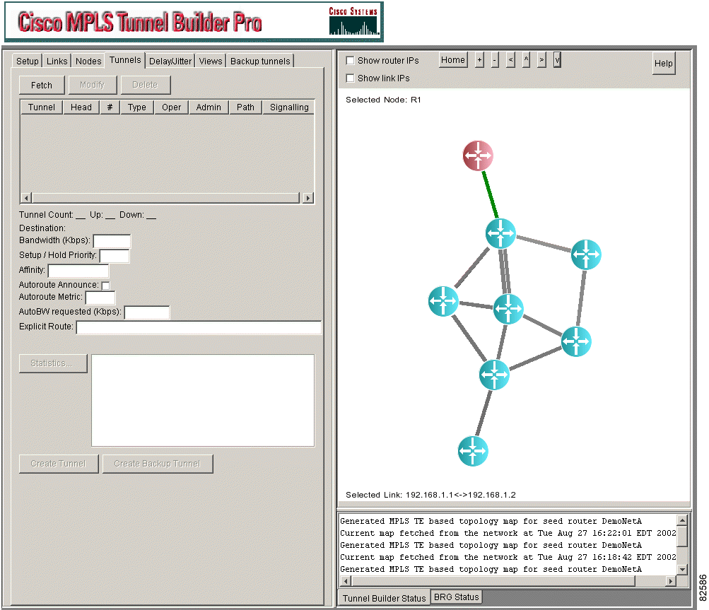
Step 2 Click Fetch. The Tunnel Information window in Figure 7-2 shows the following information for the tunnel:
The information in the Oper, Admin, Path, and Signalling fields is current as of one of the following events, whichever occurred last:
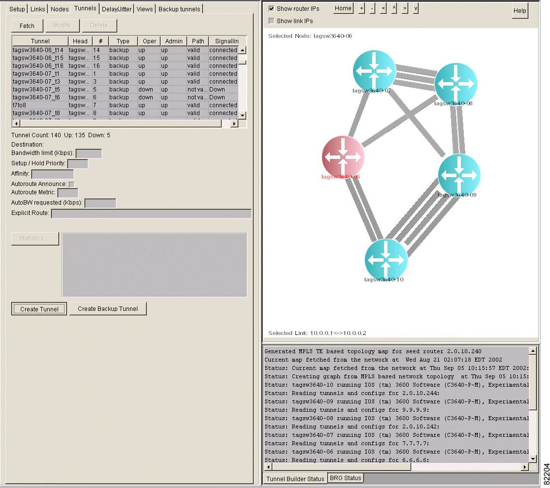
Step 3 To display additional information about an existing tunnel, select a tunnel in the table. The following information appears:
To modify a primary tunnel, perform the following steps:
Step 1 Click the Tunnels tab. The Tunnels window shown in Figure 7-3 appears.

Step 2 Click Fetch. The tunnels are listed in the list box, as shown in Figure 7-4.

Step 3 Select the tunnel that you want to modify in the Tunnels list box or right-click the tunnel in the network map.
Step 4 Click Modify. The Confirmation message shown in Figure 7-5 appears, unless you previously disabled it.
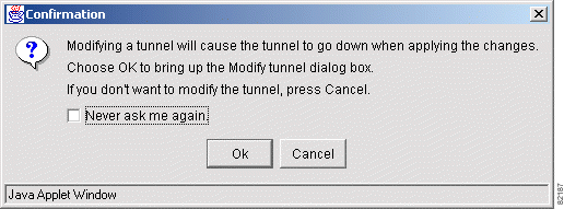
Step 5 If you receive the Confirmation message, click OK or Cancel. If you click OK, the Modify Tunnel window shown in Figure 7-6 appears.
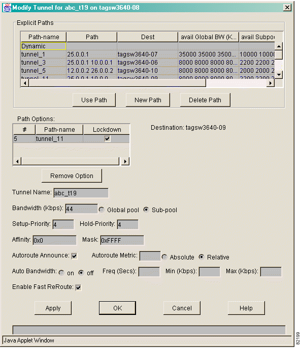
Step 6 You can change any or all of the following items:
 |
Note If you do not enter a value for the Bandwidth, Setup-Priority, Hold-Priority, Affinity, or Autoroute Metric field, the tunnel is configured with the default values specified on the head-end node. |
Step 7 Click Apply or OK.
This section contains the following procedures:
To view TE link parameters, perform the following steps:
Step 1 Click the Links tab. The Links window shown in Figure 7-7 appears.
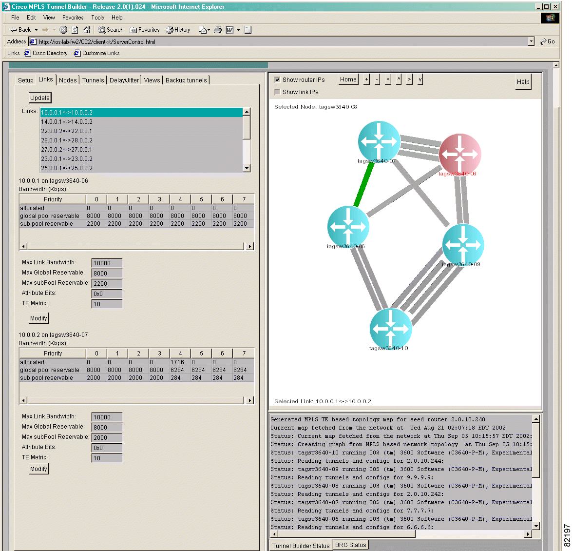
Step 2 To view the traffic engineering attributes of a link, do one of the following:
The link is highlighted in green on the network map.
The following bandwidth parameters are displayed for priority 0 through priority 7 traffic, in kilobytes per second:
The following interface parameters are displayed:
 |
Note If the router for the link is running a version of Cisco IOS that does not support subpool bandwidth, the Max subPool Reservable field is not displayed. |
 |
Note You can modify all the fields except the TE Metric. |
You can modify the TE link parameters.
To modify TE link parameters, perform the following steps:
Step 1 (Optional) Click the Links tab. The Links window shown in Figure 7-8 appears.

Step 2 In the Links list box, select the link for which you want to change values. The selected link is highlighted in green in the network map.
Step 3 You can change any or all of the following values:
 |
Note You can modify a link at either end of the node. Be sure to modify the values for the correct interface. |
Step 4 Click Modify.
Step 5 (Optional) To update bandwidth allocation information, click Update. The information will be accurate as of the last BGP update.
This section contains the following procedures:
To view TE node parameters, perform the following steps:
Step 1 Click the Nodes tab. The Nodes window shown in Figure 7-9 appears.
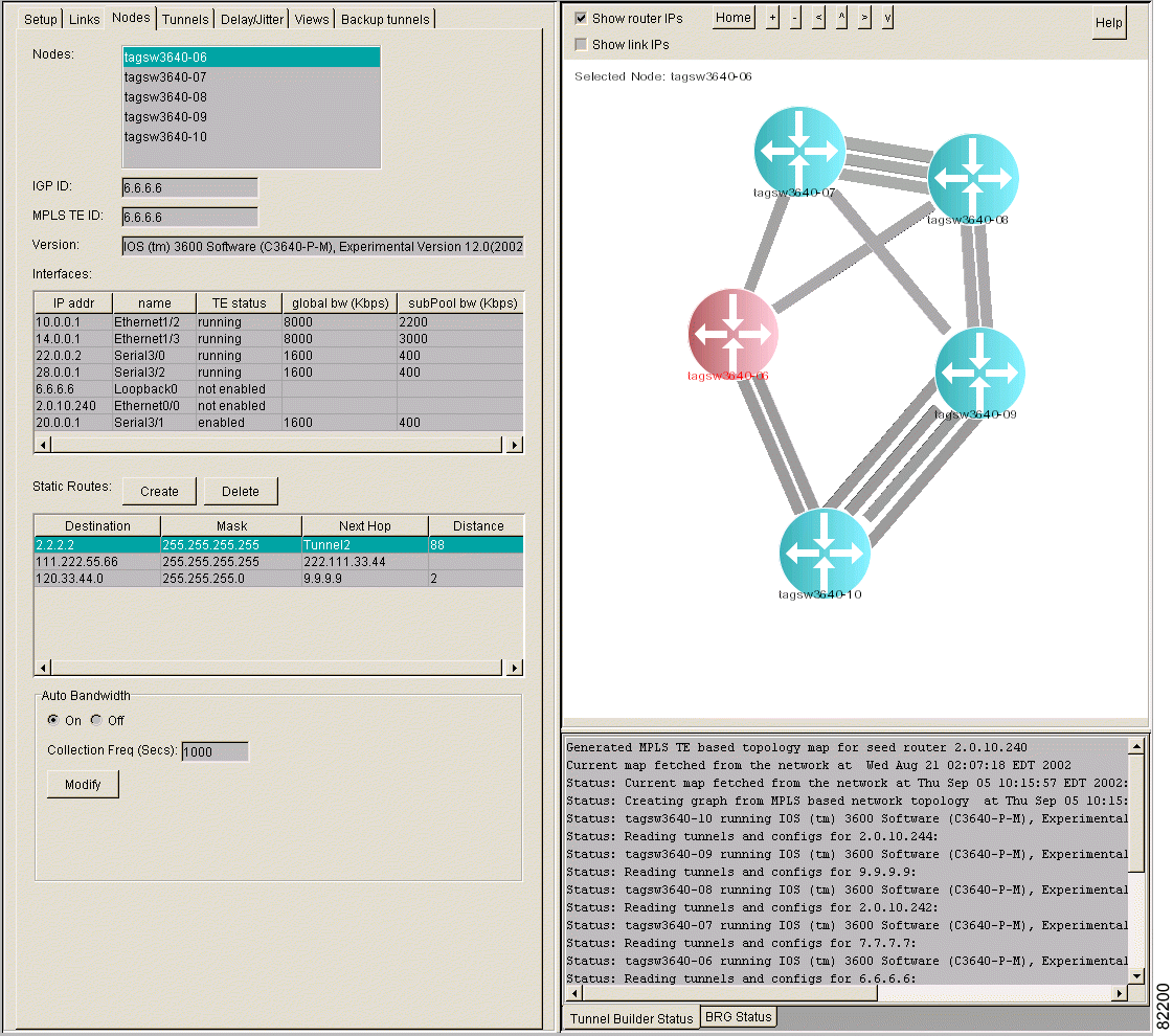
Step 2 To select the node for which you want to view information, do one of the following:
The following information for that node is displayed:
 |
Note If a node does not have MPLS TE configured correctly, it has an ID of 0.0.0.0 in the Nodes list box and in the network map. |
When you modify TE node parameters, you can do the following:
A static route is useful for mapping traffic onto tunnels. To create a static route, perform the following steps:
Step 1 Click the Nodes tab. The Nodes window shown in Figure 7-10 appears.

Step 2 Do one of the following:
The Create Static Route popup window shown in Figure 7-11 appears.
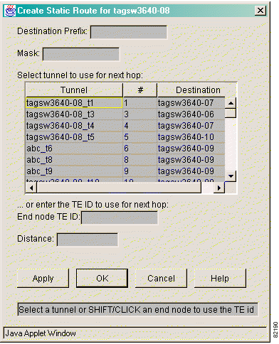
Step 3 In the Destination Prefix field, enter the destination prefix of the static route.
Step 4 In the Mask field, enter the mask for the destination IP address.
Step 5 To select the tunnel that you want to use for the next hop, do one of the following:
Step 6 (Optional) If you want a dynamic route to override the static route, enter a distance metric in the Distance field.
Step 7 (Optional) To create more static routes, click Apply and repeat Steps 2 through 6.
Step 8 When you are done creating static routes, click OK. For each static route that has been configured for a selected node, you can view the following information:
To delete a static route, perform the following steps:
Step 1 Click the Nodes tab.
Step 2 Select the static route.
Step 3 Click Delete.
To control autobandwidth, perform the following steps:
Step 1 Click the Nodes tab. The Nodes window shown in Figure 7-12 appears.

Step 2 In the Nodes list box, select the node for which you want to control autobandwidth.
Step 3 In the Auto Bandwidth field, click On if you want autobandwidth configured on that node. If you do not want autobandwidth configured on that node, click Off.
 |
Note If the selected node does not support the Auto Bandwidth feature, the On and Off buttons are not displayed. |
Step 4 Specify the collection frequency, in seconds (that is, the number of seconds between samples of the tunnel output rate). The default is 86400 seconds (1 day).
Step 5 Click Modify.
The Tunnel Builder Pro application provides timely notification to the user of interface up or interface down events that affect any links in a network map.
To make your changes permanent, see "Make Your Changes Permanent" in "Using Tunnel Builder Pro for the First Time."
![]()
![]()
![]()
![]()
![]()
![]()
![]()
![]()
Posted: Fri Oct 11 11:22:42 PDT 2002
All contents are Copyright © 1992--2002 Cisco Systems, Inc. All rights reserved.
Important Notices and Privacy Statement.