|
|

This chapter provides information you need to do the following:
For information about setting up backup tunnel calculations, and setting up Backup Route Generator (BRG) options that are used in performing compute backup and check protection operations, see "Protecting Your Network."
To understand if your network is protected, see the following sections:
Three types of elements can be protected using Tunnel Builder Pro:
 |
Note It may not always be possible to create backup tunnels; the topology may not permit it, or some nodes may not conform to Fast Reroute requirements. You can use affinity bits and/or explicit paths to ensure that primary tunnels are not routed through unprotected links or SRLGs. See "Managing Primary Tunnels." |
The section describes the following:
Next-hop (NHOP) backup tunnels protect against the failure of a link that is part of a primary tunnel's label-switched path (LSP). An NHOP backup tunnel terminates at a node adjacent to the head router.
If a link is in an SRLG, for each link in the SRLG Tunnel Builder Pro finds one NHOP backup tunnel that avoids all links in the SRLG. A link can belong to a maximum of one SRLG.
If a link is not in an SRLG, Tunnel Builder Pro simply finds an NHOP backup tunnel that avoids the link being protected.
Figure 4-1 illustrates backup tunnels that protect against link and SRLG failures.
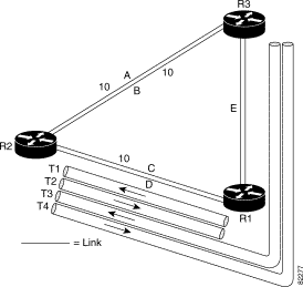
The illustration shows the following:
If the SRLG fails, the following occurs:
To protect against the failure of a node, Tunnel Builder Pro creates next-next-hop (NNHOP) backup tunnels that bypass the protected node. The backup tunnels must start and terminate at neighbors of the node being protected.
Tunnel Builder Pro also creates NHOP tunnels to protect against the failure of a link with primary tunnels terminating at the failed node. If a node fails, these NHOP tunnels are activated only until each neighbor node can determine whether an apparent interface failure indicates a link or node failure. Tunnel Builder Pro ensures that there is sufficient bandwidth for these NHOP and NNHOP tunnels because they are activated simultaneously if a node fails.
To ensure the compatibility of NHOP and NNHOP tunnels that are invoked when a node fails, do the following:
 |
Note When creating an NNHOP tunnel to protect a flow through a router, if the head link of the flow belongs to an SRLG, the NNHOP will avoid other members of that SRLG. If a link is incoming to the NHOP, each backup tunnel (depending on the NNHOP it is protecting) will have a specific set of SRLGs to avoid. |
Figure 4-2 illustrates backup tunnels that protect against node failures.
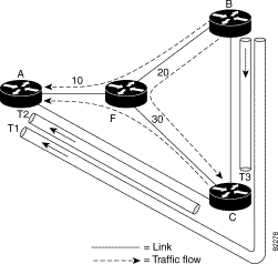
The illustration shows the following network:
| Backup Tunnel | Backup Tunnel Path | Protected Traffic Flow | Backup Tunnel's Bandwidth |
|---|---|---|---|
T1 | B—C—A | B—F—A | 10 |
T2 | C—A | C—F—A | 10 |
T3 | B—C | B—F—C | 20 |
When the router fails, backup tunnel T1 is activated to carry any traffic that was carried by primary tunnels using the path B—F—A, and backup tunnel T2 is activated to carry any traffic that was carried by primary tunnels using the path C—F—A.
For an explanation of load balancing, see "Protecting Your Network." For a more detailed explanation, see the MPLS TE Link and Node Protection, with RSVP Hello Support feature module.
MPLS traffic engineering (TE) allows constraint-based routing (CBR) of IP traffic. One of the constraints satisfied by CBR is the availability of required bandwidth over a selected path. DiffServ-aware TE extends MPLS TE to enable you to perform CBR of "guaranteed" traffic, which satisfies a more restrictive bandwidth constraint than that satisfied by CBR for regular traffic. The more restrictive bandwidth is called a subpool, while the regular TE tunnel bandwidth is called the global pool. (The subpool is a portion of the global pool.) This ability to satisfy a more restrictive bandwidth constraint translates into an ability to achieve higher quality of service (QoS) performance (in terms of delay, jitter, or loss) for the guaranteed traffic.
Tunnel Builder Pro analyzes the TE topology of a network and recommends where to place backup tunnels in order to provide bandwidth protection in the event of a single element failure. To perform this analysis, Tunnel Builder Pro defines primary bandwidth and backup bandwidth.
This section describes the following:
Primary bandwidth is the total bandwidth to be protected on a link. If that link or either of its endpoints fails, the traffic using the primary bandwidth of this link (that is, primary traffic) will be rerouted. For information about primary traffic for link versus node failure, see "Protecting Elements".
If any other element on the network fails, any traffic rerouted across this link will not interfere with traffic using the primary bandwidth of this link.
There are two possible settings for primary bandwidth in Tunnel Builder Pro:
Backup bandwidth is the total bandwidth available to accommodate backup tunnels without interfering with the primary traffic on the link. The default is the actual link speed minus the primary bandwidth. You can change the default by underbooking or overbooking bandwidth using the link speed factor.
Tunnel Builder Pro provides a facility for underbooking or overbooking link capacity in the event of an element failure. To do this, set the link speed factor, which is a global variable. Table 4-2 describes link speed factor settings for underbooking and overbooking backup bandwidth.
| Link Speed Factor Setting | Meaning |
|---|---|
1 | (Default) Desired backup bandwidth is the link speed minus the primary bandwidth. |
Less than 1 | Underbooking of the link capacity is desired. For example, use underbooking to accommodate delay and jitter constraints if there are microbursts of traffic. |
Greater than 1 | Overbooking of the link capacity is tolerable in the event of a single element failure. |
Tunnel Builder Pro is often used to provide bandwidth protection for all reservable traffic in the network. This application is typically used in regular MPLS traffic engineering where only a single class type is defined. The amount of primary traffic is limited by the maximum reservable (global) bandwidth. The goal is to back up all the maximum reservable (global) bandwidth on any link.
To provide bandwidth protection to all reservable traffic, click the Backup Tunnels tab and select Backup Any pool. The backup pool will then be the link speed minus the maximum reservable (global) bandwidth. To avoid load balancing of backup tunnels, set the maximum reservable (global) bandwidth to be significantly less than the link speed (approximately 70 percent or less than the value of the link speed) on the majority of the links. See "Bandwidth Sharing".
DiffServ-aware Traffic Engineering allows you to define several class-types and limit the maximum amount of traffic of each class-type to a specified amount, referred to as maximum reservable bandwidth of the class-type.
Tunnel Builder Pro supports two class-types, and the following bandwidth pools on each link:
To provide stringent worst case delay and jitter guarantees to delay-sensitive traffic such as VoIP in routers implementing aggregate class-based scheduling, limit the total amount of delay-sensitive traffic on any link to a predetermined fraction of the link bandwidth.
Tunnel Builder Pro can be used to guarantee the bandwidth of delay-sensitive traffic if the following conditions exist:
To provide bandwidth guarantees only to subpool traffic, click the Backup Tunnels tab and then select Backup sub pool only.
You can also select the backup pool by subtracting the maximum reservable subpool bandwidth from the link speed.
If the link speed factor is 1, then the subpool traffic on any link plus the backup traffic routed through this link in case of a failure elsewhere in the network cannot exceed the link speed. The subpool traffic is ensured a bandwidth guarantee in the presence of a single failure. However, because in the presence of a failure the combined backup and primary subpool traffic is no longer limited by a desired fraction of the link speed, delay and jitter characteristics may be degraded. Such a degradation may be unacceptable.
To maintain low delay and jitter for the subpool traffic in the event of a failure, configure the link speed factor to be the desired fraction of the link bandwidth. For example, set the maximum reservable subpool bandwidth to 25 percent of each link, and configure the link speed to be 0.5. In this case, the combined primary and backup subpool traffic will not exceed 50 percent of any link.
Backup tunnels are established with zero bandwidth reserved. Thus, in the absence of a failure the best-effort traffic using the global pool can use the entire bandwidth of the link not used by primary subpool traffic. However, because the subpool traffic is scheduled at a higher priority than the global pool traffic, when a failure occurs the entire backup pool becomes immediately available to subpool backup traffic. That ensures the desired level of bandwidth protection.
Bandwidth protection is not provided for best-effort traffic. However, connectivity protection can be provided for best-effort traffic in the following ways:
In both cases, bandwidth is guaranteed to the subpool traffic because it is scheduled at a higher priority, but protection for best-effort traffic remains "best-effort" with no bandwidth guarantees.
If the majority of all traffic in the network is best-effort traffic (which can typically cause congestion), you may not need to provide strict bandwidth protection. To limit the amount of overbooking (and resulting congestion) that may occur on any link if there is a failure, increase the link speed factor accordingly. Example: If the link speed factor is 1.5, if there is a failure, no link is overloaded by more than a factor of 1.5.
Bandwidth sharing is based on the principal of independent failures. It is unlikely that there will be multiple failures simultaneously, so a backup tunnel is used only for a short period of time.
A backup pool of bandwidth functions as follows:
If several backup tunnels protecting the same element (link or SRLG) are routed over the same interface, their total bandwidth is less than the backup bandwidth for that interface. However, backup tunnels protecting different elements can share backup bandwidth on any link.
Figure 4-3 illustrates how backup tunnels protecting two nodes can share bandwidth on the same link. Assuming that router A and router B will fail independently (that is, there will be only one failure at a time), the bandwidth of the link X—Y can be shared between backup tunnels protecting router A and router B. Only T1 or T2 will be active at any given time.
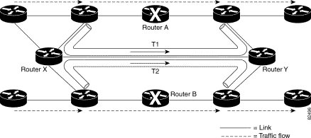
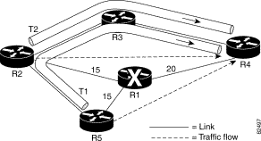
Figure 4-4 illustrates the ability of Tunnel Builder Pro to take further advantage of bandwidth sharing. The backup tunnels shown in Figure 4-4 and described in Table 4-3 protect against the failure of node R1.
| Backup Tunnel | Backup Tunnel Path | Protected Traffic Flow | Backup Tunnel's Bandwidth |
|---|---|---|---|
T1 | R5—R2—R3—R4 | R5—R1—R4 | 15 |
T2 | R2—R3—R4 | R2—R1—R4 | 15 |
T3 | not illustrated | R4—R1—R2 |
|
T4 | not illustrated | R5—R1—R2 |
|
T5 | not illustrated | R2—R1—R5 |
|
T6 | not illustrated | R4—R1—R5 |
|
Note the following:
A naive way of determining if link R3—R4 has enough bandwidth to support both T1 and T2 would be to assume that 30 Kbps of backup bandwidth is required on link R3—R4. However, the total traffic flow that is protected by T1 and T2 is only 20 Kbps because the protected traffic flows R5—R1—R4 and R2—R1—R4 both pass through link R1—R4, which only has a capacity of 20 Kbps. The algorithm used by Tunnel Builder Pro detects this type of scenario and is therefore better able to find and recommend backup tunnels with sufficient bandwidth.
For a more detailed explanation of bandwidth sharing, refer to the following IETF drafts:
This section contains the following procedures:
To interpret the results, go to the following:
Results of backup tunnel computations (Check Protection and Compute Backups) are displayed in the following areas of the Backup Tunnels window:
The following warning conditions are highlighted in the Backup Tunnels list box:
You can display information about requests to run the Tunnel Builder Pro BRG algorithm for checking or suggesting backup tunnel placement. Click the BRG Status tab in the bottom right corner of the Backup Tunnels window. The following information appears:
 |
Note To prevent inconsistent results from being displayed or deployed, Tunnel Builder Pro will only perform the following operations sequentially: compute backups, check protection, install backup tunnels, and delete backup tunnels. |
When you display backup tunnels, the highlighting on the network map shows what is protected.
 |
Note If there are parallel links, and only a subset of the parallel links is at the head link set for a particular tunnel, the head links for router backup tunnels are not displayed. |
To display backup tunnels, do the following:
Step 1 Click the Backup tunnels tab. The Backup Tunnels window shown in Figure 4-5 appears.
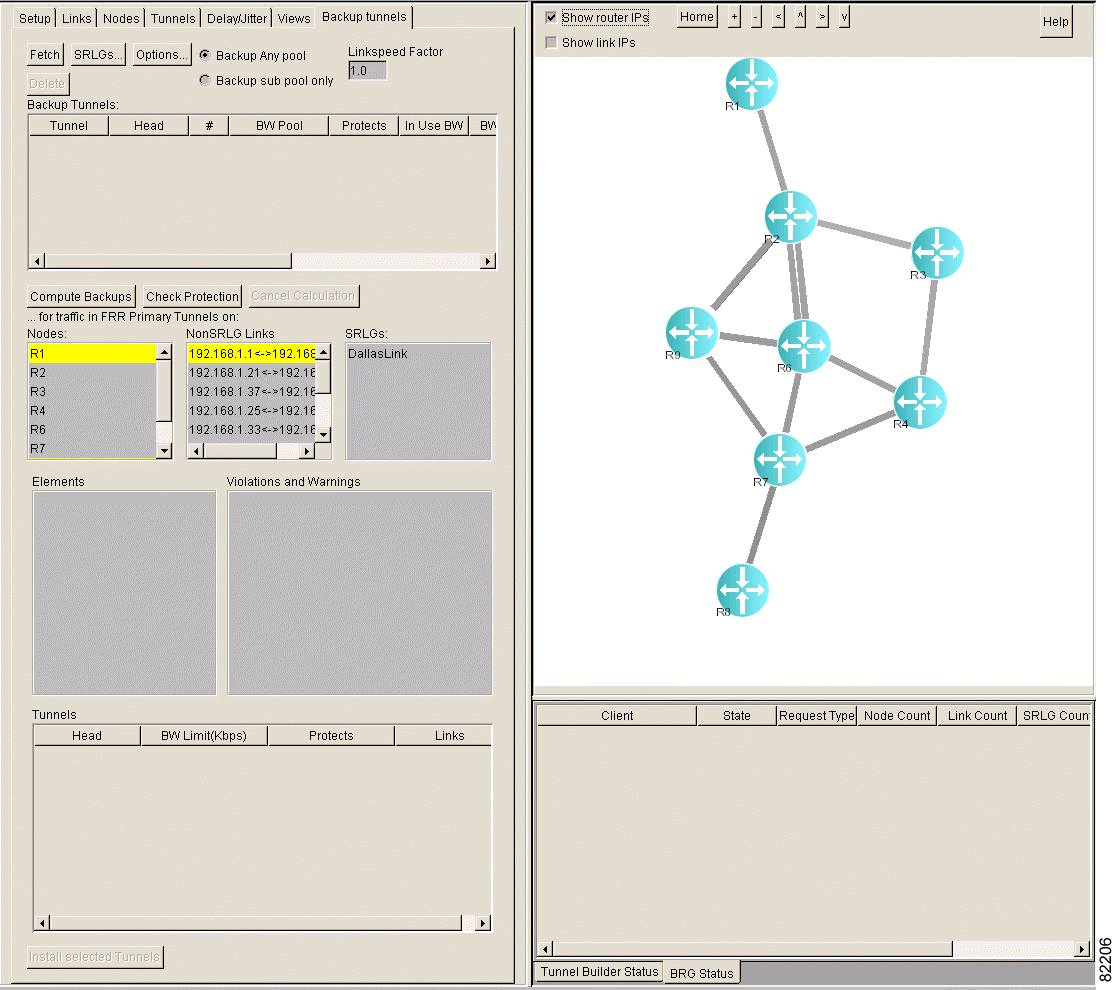
Step 2 Click Fetch.
Step 3 In the Backup Tunnels list box, select a tunnel. The selected tunnel is highlighted on the network map and the following information is displayed:
 |
Note The network map displays only the latest tunnel you selected, not all previously selected tunnels. |
 |
Note The values in the backup tunnels table (that is, Oper, Admin, Path, and Signalling) are accurate as of the last fetch from the network. |
To determine if non-SRLG links are protected, perform the following steps:
Step 1 Click the Backup tunnels tab. The Backup Tunnels window shown in Figure 4-6 appears.

Step 2 In the NonSRLG Links list box, select the links that you want to check. To select all links, select a single link in the list box and then press Ctrl-A.
Step 3 Click Check Protection. The window shown in Figure 4-7 appears.
 |
Note It may take some time to check the protection. To stop the check protection function, click Cancel Calculation. |
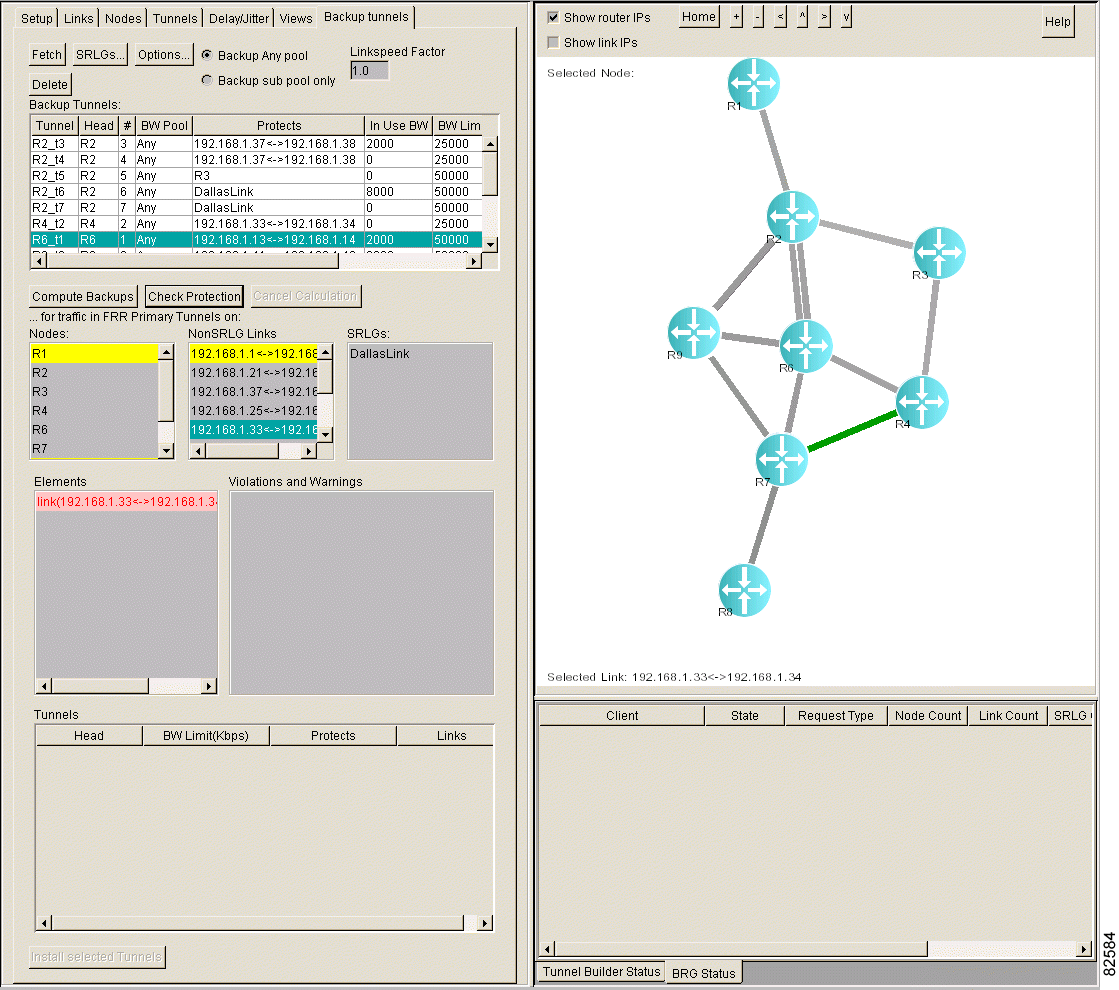
Step 4 In the Elements list box, select the link(s). Backup tunnels that protect the link(s) are highlighted in green in the Backup Tunnels list box, as shown in Figure 4-8.
If a non-SRLG link is unprotected, it is highlighted in pink in the Elements list box. The Violations and Warnings list box may contain an explanation for why the non-SRLS links are unprotected.
To interpret the colors, see "Backup Tunnel Computation Results and Color Display".
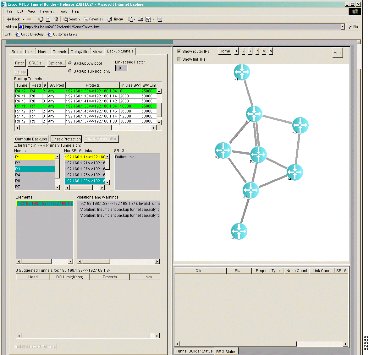
To determine if nodes are protected, perform the following steps:
Step 1 Click the Backup tunnels tab. The Backup Tunnels window shown in Figure 4-9 appears.

Step 2 In the Nodes list box, select the node(s) that you want to check. To select all nodes, select a single node and then press Ctrl-A.
Step 3 Click Check Protection.
 |
Note It may take some time to check the protection. To stop the check protection function, click Cancel Calculation. |
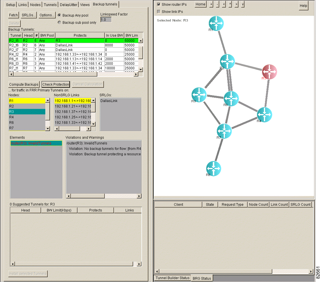
Step 4 In the Elements list box, select the node(s). Backup tunnels that protect the node(s) are highlighted in green in the Backup Tunnels list box, as shown in Figure 4-10.
If a node is unprotected, it is highlighted in pink in the Elements list box. The Violations and Warnings list box may contain an explanation for why the node is unprotected.
To interpret the colors, see "Backup Tunnel Computation Results and Color Display".
To determine if SRLGs are protected, perform the following steps:
Step 1 Click the Backup tunnels tab. The Backup Tunnels window shown in Figure 4-11 appears.

Step 2 In the SRLGs list box, select the SRLG(s) that you want to check. To select all SRLGs, select a single SRLG and then press Ctrl-A.
Step 3 Click Check Protection.
 |
Note It may take some time to check the protection. To stop the check protection function, click Cancel Calculation. |
Step 4 In the Elements list box, select the SRLGs. Backup tunnels that protect the SRLGs are highlighted in green in the Backup Tunnels list box, as shown in Figure 4-12.
If an SRLG is unprotected, it is highlighted in pink in the Elements list box. The Violations and Warnings list box may contain an explanation for why the SRLG is unprotected.
To interpret the colors, see "Backup Tunnel Computation Results and Color Display".
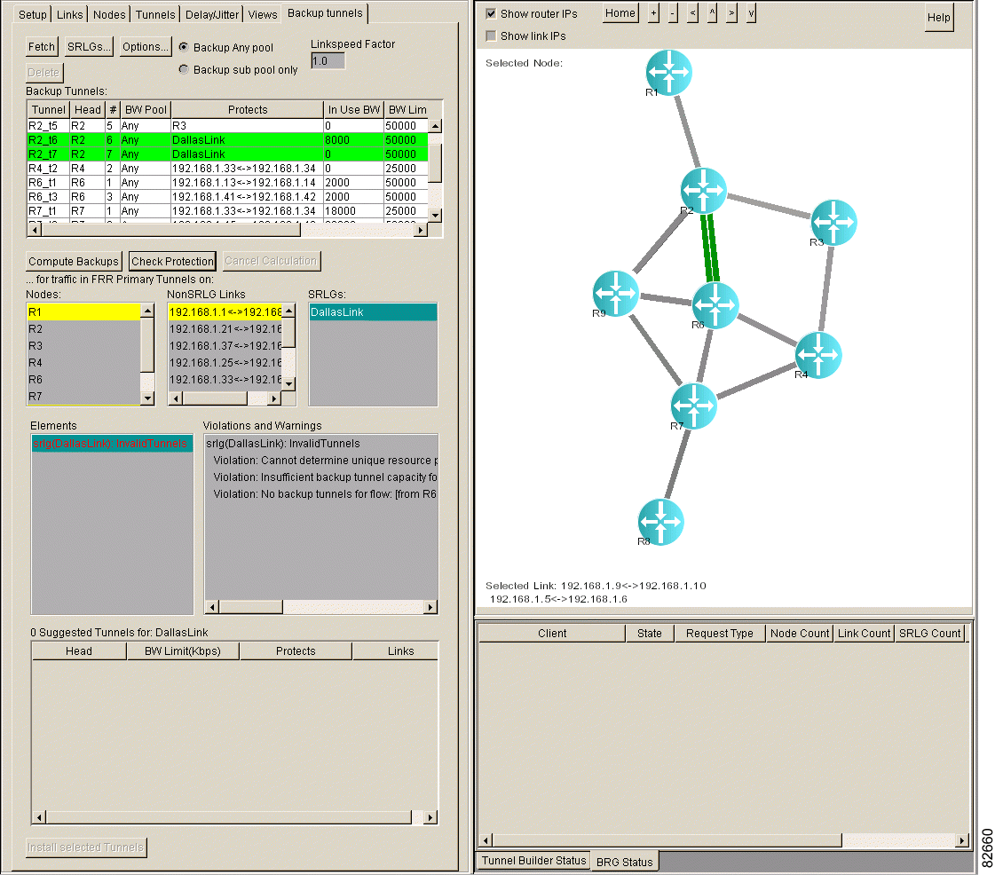
This section describes the violations and warnings that can appear when you click Check Protection.
The Violations and Warnings list box displays a message explaining why each unprotected link, SRLG, and node is not protected. Table 4-4 describes warnings. Table 4-5 describes violations.
| Message | Meaning |
|---|---|
Violation: Backup tunnel protecting a resource is routed through the resource | A backup tunnel passes through the element it is supposed to protect. |
Violation: Flow flow_description backup tunnel routed through SRLG name protects the same SRLG | A backup tunnel protects a flow through a router, but the backup tunnel passes through a link that is a member of an SRLG, and the head link of the tunnel is in the same SRLG. |
Violation: Insufficient backup tunnel capacity for flow flow_description (1000<2000) | There are backup tunnels protecting the flow, but they protect only 1000 Kbps and the bandwidth of the flow is 2000 Kbps. |
Violation: Backup tunnels routed through link xxx exceed the backup capacity of link | One or more backup tunnels that protect against the same element failure are using the same link, and the total bandwidth of these tunnels exceeds the backup bandwidth of the link. |
Violation: Cannot determine unique resource protected by backup tunnel—therefore, it is ignored | The backup tunnel is not valid for one of the following reasons:
|
Violation: No backup tunnels for Flow | No backup tunnels exist for the flow. This message may appear twice for a link, once in each direction. |
To protect non-SRLG links, SRLGs, and/or nodes, see "Protecting Your Network."
![]()
![]()
![]()
![]()
![]()
![]()
![]()
![]()
Posted: Fri Oct 11 11:19:15 PDT 2002
All contents are Copyright © 1992--2002 Cisco Systems, Inc. All rights reserved.
Important Notices and Privacy Statement.