|
|

Real-time voice over IP (VoIP) traffic in a network is directly affected by packet loss, packet delay, and delay variation. In an enterprise environment, network congestion can occur at any time in any portion of the network campus, branch office, or WAN. For successful deployment of IP telephony, you must ensure end-to-end network quality for voice traffic.
To ensure voice quality, you must use QoS in all areas of the enterprise network. To make a proper QoS configuration, you must first identify the points where QoS is a concern, then choose the appropriate QoS tools to use, and deploy to the devices in the network.
In this chapter, you will learn how to use the IP Telephony wizard to deploy QoS for VoIP over the Campus, WAN, and Branch Office segments of a network, using an example network scenario. The tutorial describes the process of configuring QoS for VoIP traffic, from selecting the devices that are in the network example, through deployment to the network and monitoring the activity and status of a deployment job.
The IP Telephony wizard creates voice policy groups that contain the QoS properties and policies required at each relevant point in your IP telephony network. The wizard determines the QoS features that can be configured in a voice policy group according to voice policy group templates which are based on the IP Telephony QoS guide. Each voice policy group contains a "voice role" attribute, which specifies the role of the interface on the network, such as, IP phone, Switch to WAN Router.
For the purpose of this tutorial, a file has been created containing the IP addresses and configuration details of the virtual devices that are in the IP telephony network configuration example. By using these virtual devices, you can follow the lessons without affecting your network. You must import the devices before you begin working on this tutorial. See Lesson 1-2: Importing the Tutorial Virtual Devices.
 |
Note If you want to create policies and deploy them using actual devices that exist in your network, you must obtain the IP addresses of the appropriate devices. |
The IP telephony network tutorial assumes that all the virtual devices in the IP telephony example network shown in Figure 3-1 have already been imported into your device inventory. Table 3-1 provides the network device information for these devices in the IP telephony network example.
This chapter includes the following sections:
Figure 3-1 shows a typical network example for configuring QoS policies for IP telephony in an enterprise environment.
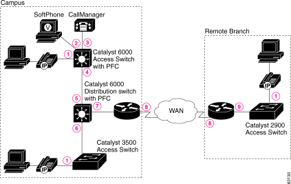
Based on this network configuration example, the following topics describe:
The campus site includes a Cisco CallManager, an IP phone, and a SoftPhone that are connected to a QoS-aware Layer 3 access switch (with PFC). An additional IP phone is connected to a Layer 2 access switch (without PFC). The IP phone ports are configured to use an auxiliary voice VLAN on the switches. Both the access switches are connected to a Catalyst 6000 PFC Layer 3 distribution switch, running IOS version 12.1. Voice data from the campus site enters the WAN from a Cisco 7200 router running IOS version 12.2.
In the campus site, you must configure QoS for IP telephony at the following network points, shown in Figure 3-1:
Because link speed in the WAN is much slower than in the LAN, QoS configuration for WAN links is needed to prevent delay. In the WAN segment of a network, the interface connections could support Serial Point-To-Point configuration or Frame Relay configuration. In this tutorial, the interface connections in the WAN segment of your network support Frame Relay configuration.
In a Frame Relay WAN configuration, you must configure the following QoS features for IP telephony on the devices interfaces (network points 8 in Figure 3-1):
The remote site includes an IP phone that is connected by means of a Layer 2 QoS-aware access switch to a Cisco 3600 router in the WAN. You must configure QoS on the IP phone port (network point 1) and on the branch office router interface to the access switch (network point 9 in Figure 3-1).
Table 3-1 shows the technical details of the devices in the IP telephony network example in Figure 3-1. These configuration details have already been imported into your device inventory so that you can follow these lessons. Interfaces that do not have QoS applied to them in the tutorial are not listed.
| Device Name | Device Model and IP Address | Software Version | Interfaces | IP Address | Mask |
|---|---|---|---|---|---|
Core-7200-1 | 7200 | 12.2 | FastEthernet0/0 FastEthernet 100,000 Kbit/sec (100 Mb/sec) | 10.9.1.1 | 255.255.255.0 |
Serial5/0 Frame Relay line at 512 Kbit/second | 10.9.2.1 | 255.255.255.0 | |||
Core-3600-2 | 3600 | 12.2T | FastEthernet0/1 FastEthernet 100,000 Kbit/sec (100 Mb/sec) | 10.8.1.1 | 255.255.255.0 |
Serial2/0 Frame Relay line at 512 Kbit/second | 10.8.2.2 | 255.255.255.0 | |||
Access-Cat6000-3 | 6509 | 6.3 | VLAN5 propVirtual | 10.6.1.2 | 255.255.255.0 |
Ethernet2/0 Standard Ethernet |
|
| |||
Ethernet2/1 Standard Ethernet |
|
| |||
Ethernet2/2 Standard Ethernet |
|
| |||
GigabitEthernet1/0 gigabitEthernet |
|
| |||
Access-Cat6000-4 | 6509 | 12.1E | GigabitEthernet1/1 gigabitEthernet | 10.7.2.2 | 255.255.255.0 |
GigabitEthernet1/2 gigabitEthernet |
|
| |||
FastEthernet2/1 FastEthernet 100,000 Kbit/sec (100 Mb/sec) | 10.51.116.191 | 255.255.255.0 | |||
Access-Cat3500-2 | 3524-PWR-XL | 12.0 | Ethernet2/3 Standard Ethernet | 10.4.1.2 | 255.255.255.0 |
GigabitEthernet0/1 gigabitEthernet |
|
| |||
Access-Cat2900-2
| 2900-XL | 12.0 | FastEthernet0/1 FastEthernet 100,000 Kbit/sec (100 Mb/sec) | 10.4.2.2 | 255.255.255.0 |
Ethernet3/1 Standard Ethernet |
|
| |||
The IP Telephony wizard helps you define your IP telephony network topology, and automatically creates the voice policy groups that will include the QoS policies required at each network point (interface) where QoS is a concern. All you must do is select the devices that are in your network topology, and the wizard will automatically assign the interfaces to the appropriate voice policy groups.
The steps of the wizard that you must follow for this lesson include:
To run the wizard, the following preconditions must be met:
This topic will help you understand the main features of the IP Telephony wizard and how to use them.
Each configuration step of the wizard includes a description of the QoS policies that will be configured on the interfaces for the selected voice role. You can view or hide this description by clicking the arrow button next to Description. By default, the description is hidden.
The Advanced section of a configuration step page provides two buttons:
You can view or hide the Advanced section by clicking the arrow button next to Advanced. By default, this section is hidden.
In each configuration step, you select the network elements that require QoS configuration. The available network elements are presented in a table. You can hide this table by clicking the arrow button next to Selection Table. By default, the selection table is open.
By selecting the Display Configuration Info. check box in the first configuration step, you can choose to view assignment summary information after each configuration step. The check box will remain selected in all the other steps. Similarly, you can deselect this check box in the first configuration step if you don't want to view the summary information. You can override the default selection at each step, if required.
As you work through the wizard, you can see a summary of the voice policy groups that were created for the current voice role, and the number of network elements that were assigned to them in the current configuration step. This summary page also includes detailed information about the network elements assignments.
You work through each step of the wizard by clicking the Next button in each page, or you can use the Navigation TOC that is displayed on the left side of each page to move directly to a particular step. Clicking Next to move to the next configuration step, or selecting another step forward in the Navigation TOC, saves the voice policy groups and the assignments that were made for that voice role, to the deployment group. Clicking Cancel, Back, or selecting another step backward in the Navigation TOC, undoes any configuration changes you made in that step.
If the Display Configuration Info. check box is selected, clicking Next opens the assignments summary page for that configuration step. The voice policy groups will be saved in the deployment group, but the assignment of interfaces to them will not be saved. After reviewing your assignments summary, clicking Next in this page saves both the voice policy groups and the interface assignments, and opens the next step of the wizard.
The first step of the wizard includes an overview of why QoS configuration is necessary for VoIP networks, and how the wizard will guide you to configure QoS for IP telephony.
This step also displays the name of the deployment group that is currently open, and will be used by the wizard for defining the IP telephony policies. If the displayed deployment group is not the one you require, you can change it.
Step 1 Select Configure > IP Telephony. The Introduction page of the wizard appears.
Step 2 If the displayed deployment group is not "Tutorial", select it from the deployment group list box.
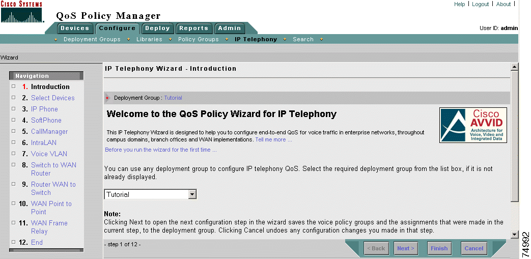
Step 3 Click Next or select Select Devices in the Navigation TOC, to move to Step 2 of the wizard.
In this step of the wizard, you select the devices you want to configure for voice QoS. All the devices that you imported from your virtual devices file, that support IP telephony features (according to model and OS), are displayed in a table. By default, the wizard selects all the devices.
Devices that do not support IP telephony are not displayed. If required, you can see all the devices in your device group and whether they support QoS for voice, in the Voice Ready report.
 |
Note If you opened the IP Telephony wizard before you imported your devices, no devices will be displayed. You should click Cancel to exit the wizard, and open the Import Devices wizard. See Lesson 1-2: Importing the Tutorial Virtual Devices. |
The wizard will assign any selected devices that require global configuration to the appropriate voice policy groups with a Voice Device voice role.
Step 1 Select the following devices by selecting the check boxes next to them:
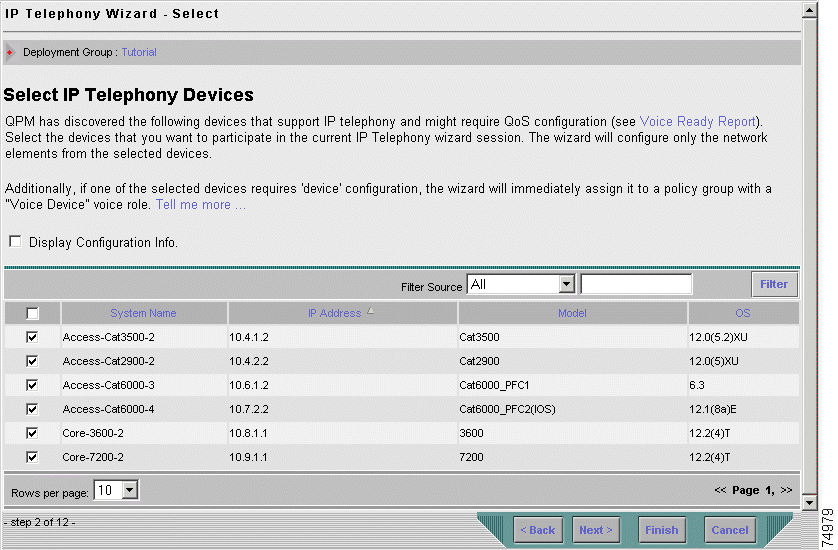
Step 2 To see all the devices in your device group, and whether they support QoS for voice, click the Voice Ready Report link. The Voice Ready report appears.
Step 3 Select/deselect to view the Assignment Summary page:
Step 4 Click Next or select IP Phone in the Navigation TOC.
The wizard saves the assignment of the selected devices to the appropriate voice policy groups with a Voice Device voice role, and the next configuration step of the wizard appears.
After you have selected all the devices in your IP telephony network that require QoS configuration, you must define the connections for each voice role.
In this step of the wizard, you select the switch ports on which the wizard will configure the QoS settings for all your IP phone connections in the network (network points 1 in Figure 3-1).
Step 1 Select the check box next to the Et2/0 port to configure QoS on the IP phone port connection to the Catalyst 6000 Layer 3 access switch in the campus.
Step 2 Select the check box next to the Ethernet2/3 port to configure QoS on the IP phone port connection to the Catalyst 3500 Layer 2 access switch in the campus.
Step 3 Select the check box next to the Ethernet3/1 port to configure QoS on the IP phone port connection to the Catalyst 2900 Layer 2 access switch in the remote branch.
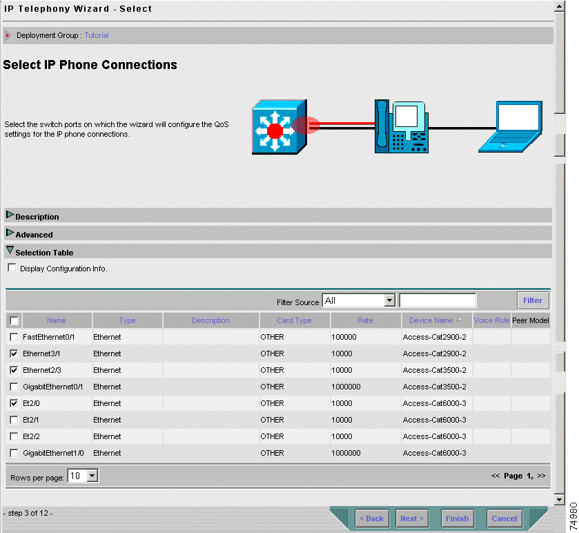
Step 4 Click Next.
The selected IP phone ports will be assigned to the appropriate voice policy groups with an IP Phone voice role. The wizard saves the assignment and the next configuration step of the wizard appears.
This step allows you to select the switch port on which the wizard will configure the QoS settings for the SoftPhone connection in your network (network point 2 in Figure 3-1).
Step 1 Select the check box next to the Et2/1 Ethernet port on which to configure QoS for the SoftPhone connection to the Catalyst 6000 Layer 3 access switch in the campus.
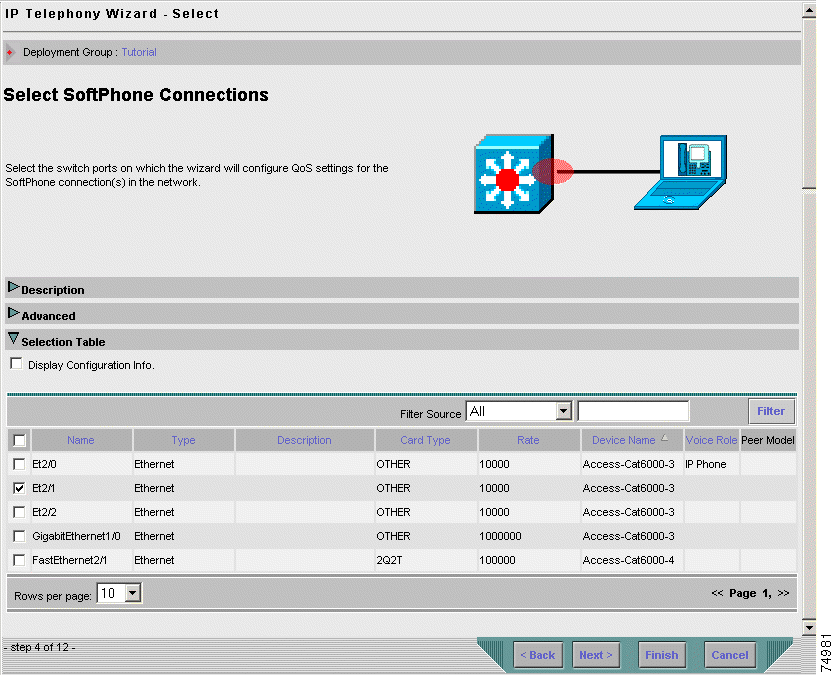
Step 2 Click Next.
The selected SoftPhone port will be assigned to the appropriate voice policy group(s) with a SoftPhone voice role. The wizard saves the assignment and the next configuration step of the wizard appears.
This step allows you to select the switch port on which the wizard will configure the QoS settings for the CallManager connection in your network (network point 3 in Figure 3-1).
Step 1 Select the check box next to the Et2/2 Ethernet port on which to configure QoS for the CallManager connection to the Layer 3 Catalyst 6000 access switch in the campus.
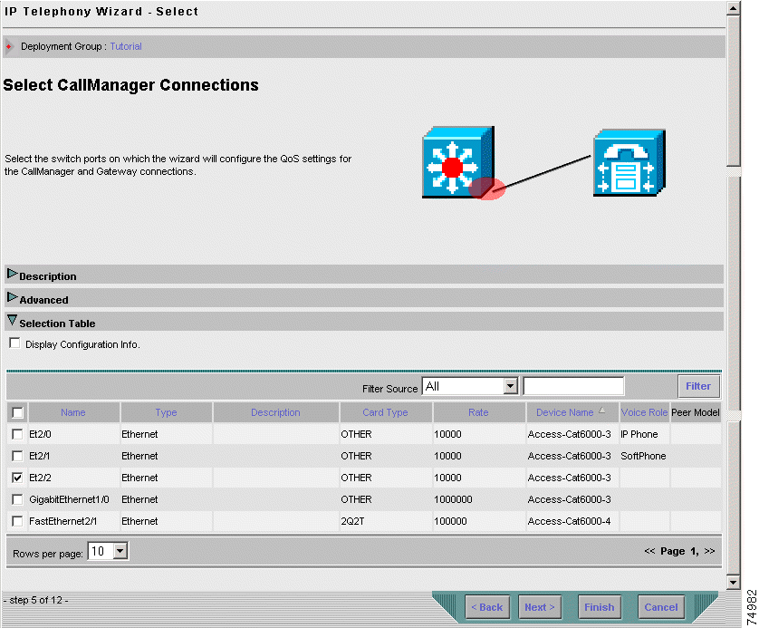
Step 2 Click Next.
The selected CallManager port will be assigned to the appropriate voice policy group(s) with a CallManager voice role. The wizard saves the assignment and the next configuration step of the wizard appears.
After configuring the QoS access interfaces, you must configure QoS throughout the LAN.
In this step, the wizard helps you define the appropriate QoS for the internal LAN ports—the uplinks and downlinks (network points 4, 5 and 6 in Figure 3-1).
 |
Note No QoS configuration is required on the uplink port of the Layer 2 Catalyst 3500 switch to the Layer 3 distribution switch port. |
The correct QoS for LAN switches connection is to trust DSCP from Layer 3 devices and trust CoS from Layer 2 devices. The wizard will configure the QoS automatically according to the type of neighboring switch. If there is no neighboring switch (or if the switch is of unknown type), QPM will configure trust CoS.
Step 1 Select the check boxes next to the following switch interfaces to configure QoS for the LAN connections in the network:
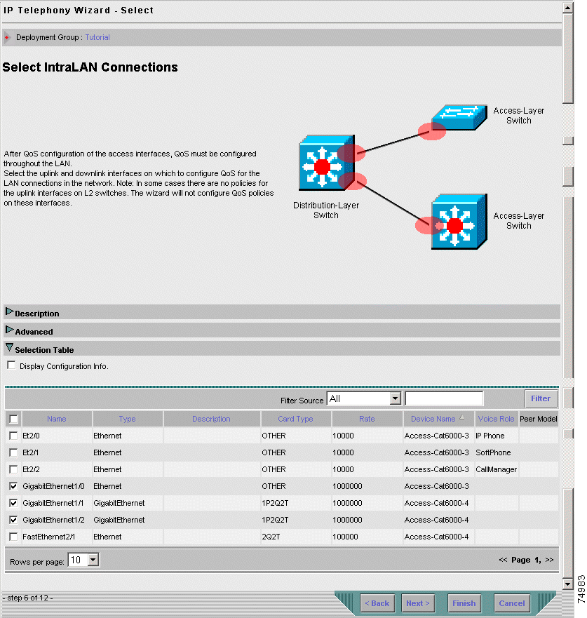
Step 2 Click Next.
The selected interfaces will be assigned to the appropriate voice policy groups with an IntraLAN voice role. The wizard saves the assignment and the next configuration step of the wizard appears.
Since the IP phone ports are configured to use an auxiliary voice VLAN on the switches, and the QoS style on the IP phone ports is set to VLAN-based, it is essential to configure the appropriate policies on the voice VLAN. In this step, the wizard configures VLAN based QoS for the VLAN on which the IP phone ports and the Layer 2 switch to Layer 3 switch connections are configured.
Step 1 Select the check box next to the VLAN5 network element to configure VLAN based policies for the voice VLANs.
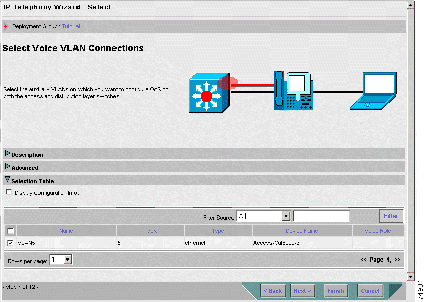
Step 2 Click Next.
The selected VLAN will be assigned to the appropriate voice policy groups with a Voice VLAN voice role. The wizard saves the assignment and the next configuration step of the wizard appears.
In this step, the wizard sets QoS for the Catalyst 6000 distribution switch interface to the Core-7200 WAN router (network point 7 in Figure 3-1).
Because traffic coming from the WAN side is already classified, the QoS configuration for the distribution switch interface to the router will be to trust the layer 3 DSCP bits.
Step 1 Select the check box next to the FastEthernet2/1 interface in the table, to configure QoS for the distribution switch connection to the WAN router.
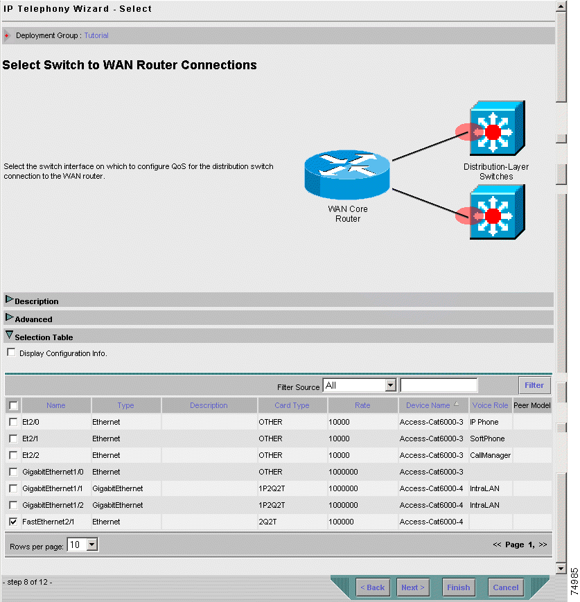
Step 2 Click Next.
The selected interface will be assigned to the appropriate voice policy groups with a Switch to WAN Router voice role. The wizard saves the assignment and the next configuration step of the wizard appears.
In this step, the wizard sets QoS for the router connection to the Catalyst 3500 access (layer 2 QoS aware) switch in the branch office (network point 9 in Figure 3-1).
By default, a router trusts the interface to a distribution (layer 3 QoS aware) switch, so there is no need to set QoS for the router connection to the Catalyst 6000 distribution switch in the campus.
Step 1 Select the check box next to the FastEthernet0/1 interface to configure QoS for the Core-3600-2 router interface to the Catalyst 2900 access switch.
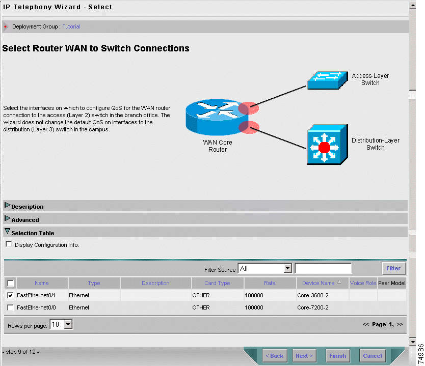
Step 2 Click Next.
The selected interfaces will be assigned to the appropriate voice policy groups with a Router WAN to Switch voice role. The wizard saves the assignment and the next step that you must configure in the wizard will open.
 |
Note Since the IP telephony network example is configured with Frame Relay and does not support Serial Point-to-Point configuration, you will skip the WAN Point-to-Point Connections configuration step. |
In this step of the wizard, you select the Frame Relay DLCI's WAN links (network points 8 in Figure 3-1). When you assign a role to a DLCI, the role will also be assigned to the main interface to which the DLCI belongs. QPM configures both the DLCIs and the interfaces.
You must select all the Frame Relay interfaces (from both the central and the remote sites) that carry voice traffic. The wizard will automatically configure QoS separately for groups of interfaces, according to their link speed.
Step 1 Select the check box next to the Serial2/0 interface to configure QoS for the Frame Relay DLCI WAN link in the remote site.
Step 2 Select the check box next to the Serial5/0 interface to configure QoS for the Frame Relay DLCI WAN link in the campus site.
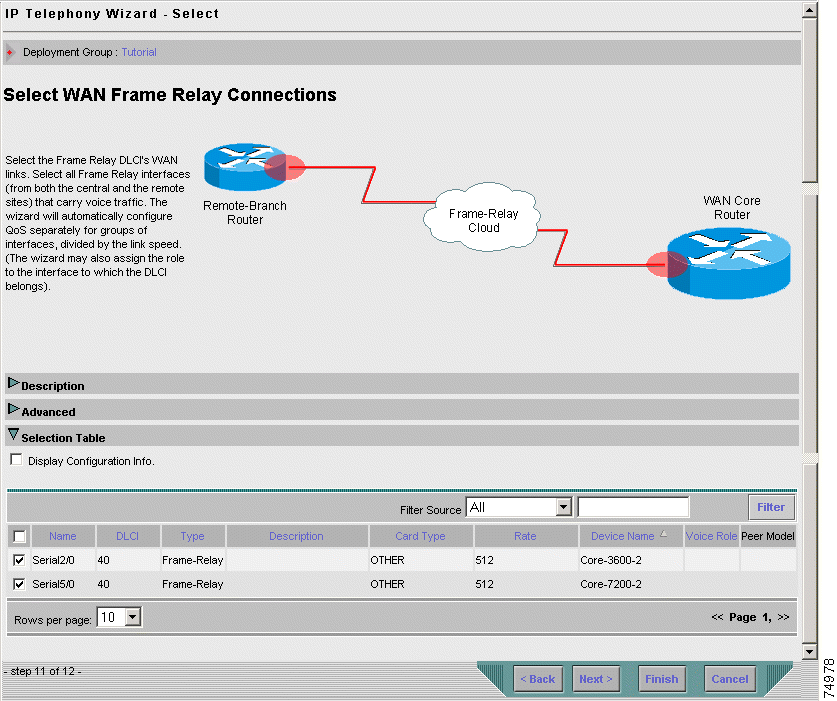
Step 3 Click Next or select End in the Navigation TOC.
The selected interfaces will be assigned to the appropriate voice policy groups with a WAN Frame Relay voice role. The wizard saves the assignment and the final step of the wizard appears.
The final step of the wizard informs you that all the QoS settings have been completed and that the wizard has added and saved the policies in your deployment group.
From this page, you can go directly to the Deployment wizard to deploy the deployment group, or to the Policy Groups page to view a detailed summary of all the voice policy groups that you created in the wizard. From the Policy Groups page, you can modify the properties and policies configured in the voice policy groups.
For the purpose of this tutorial, you should select to go to the Policy Groups page and follow the next lesson, which describes how to modify one of the voice policy groups that you created in this lesson.
Step 1 Select the No radio button in the End page of the wizard.
Step 2 Click Finish to close the wizard.
The Policy Groups page appears.
QPM allows you to customize policies to suit specific network configurations by modifying the voice policy groups. After you have completed the IP Telephony wizard, you can modify properties and policies of the voice policy groups created by the wizard. QPM allows you to modify any of the properties and policies of a voice policy group, except for its device constraints. Changing the device constraints will cause the voice policy group to lose its voice role. In this case, the IP Telephony wizard will be unable to assign network elements to the voice policy group.
 |
Note You cannot modify a policy group that is linked to a policy group template. Whenever you want to modify a policy group created by the IP Telephony wizard, you must first disconnect the policy group from the template, or modify the template. |
In this lesson, you will learn how to modify the following WAN Frame Relay voice policy groups that were created in Step 10: Selecting the WAN Frame Relay Connections of the wizard:
To do this lesson you should have completed Lesson 3-1: Assigning Voice Policies Using the IP Telephony Wizard.
After you have completed the IP Telephony wizard and you selected not to deploy your QoS policies, as described in Step 11: End, the Policy Groups page automatically appears. The Policy Groups page displays all the voice policy groups that were created by the wizard. For each voice policy group, its associated voice role is displayed.
 |
Tip You can also open the Policy Groups page by selecting Configure > Policy Groups. |
This lesson is divided into the following two lessons:
By compressing the RTP header in an RTP data packet (cRTP), you can reduce the delay for voice traffic transmission. In this lesson, you will learn how to enable cRTP for the WAN-FR-Main-Interface voice policy group.
Step 1 In the Policy Groups page, click the WAN-FR-Main-Interface policy group name in the table (you might need to open page 2 to find it). The General page appears, displaying general definitions for the selected policy group.
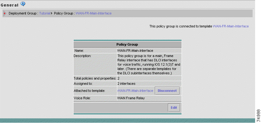
Step 2 Click Disconnect to disconnect the voice policy group from the template. The Edit button at the bottom of the page becomes active.
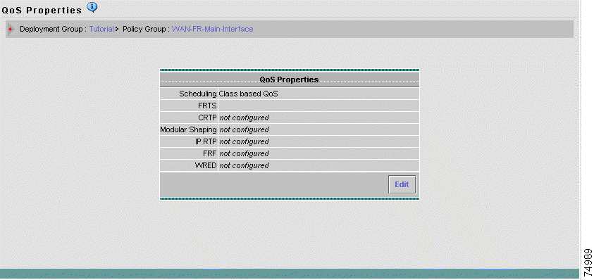
Step 3 In the Policy Group TOC, select QoS Properties. The QoS Properties page appears.
 |
Note cRTP is not configured. |
Step 4 Click Edit in the QoS Properties page. The QoS Properties wizard—Congestion Management page appears.
Step 5 Select Traffic Control Settings in the Navigation TOC.
The QoS Properties wizard—Traffic Control Settings page appears, displaying the traffic control parameters that were configured by the IP Telephony wizard for the WAN-FR-Main-Interface voice policy group.
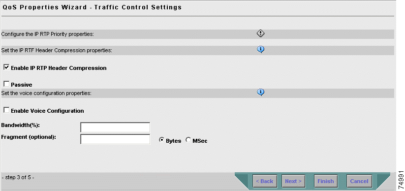
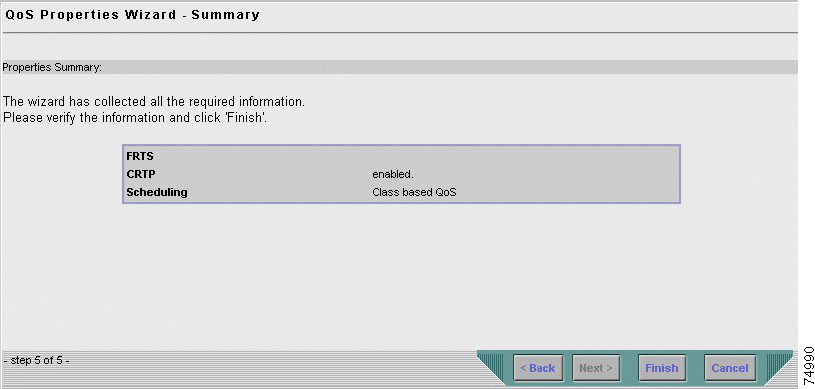
Step 6 Select the Enable IP RTP Header Compression check box, and click Finish. The QoS Properties Wizard Summary page appears, in which you can view a summary of the QoS properties defined for the voice policy group.
 |
Note cRTP is now enabled for the voice policy group. |
Step 7 Click Finish to save the changes.
The QoS Properties page appears, displaying the modified configuration. cRTP is now configured for this voice policy group.
Step 8 Select Configure > Policy Groups. The Policy Groups page appears.
Step 9 Continue with Lesson 3-2-2: Configuring the Voice Traffic Bandwidth for the WAN-FR-DLCI-Slow Voice Policy Group.
In this lesson, you will learn how to modify the WAN-FR-DLCI-Slow voice policy group, by creating a QoS policy that configures the percentage of bandwidth on the interface that should be reserved for your voice traffic.
You can create policies in a policy group, or in a policy group template. This lesson describes how to modify the WAN-FR-DLCI-Slow policy group template to create the QoS policy. Changes made in the policy group template will also apply to the attached voice policy group—WAN-FR-DLCI-Slow.
A QoS policy contains a filter and actions, so you will need to define the filter for the policy, and then the policy action(s). A filter can contain filter condition(s) which you must also define for the filter rule. After it is created, the new QoS policy will be added to the outbound policies currently defined for the template.
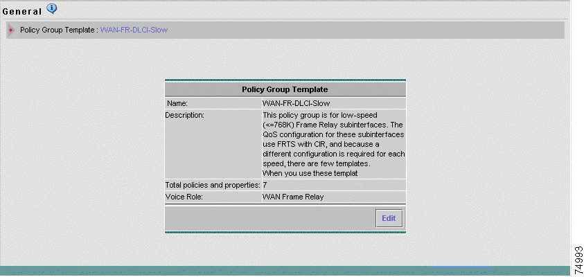
Step 1 In the Policy Groups page, click the WAN-FR-DLCI-Slow policy group template name in the table (you might need to open page 2 to find it). The General page for the policy group template appears, displaying general definitions for the selected template.
Step 2 In the Policy Group TOC, select Out Policies. The Out Policies page appears, displaying the current outbound policies defined for the template.
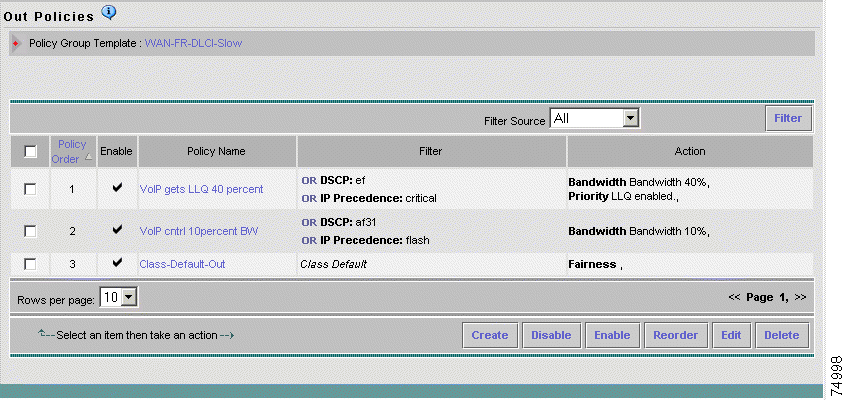
Step 3 Click Create in the Out Policies page. The General page of the Out Policy wizard appears.
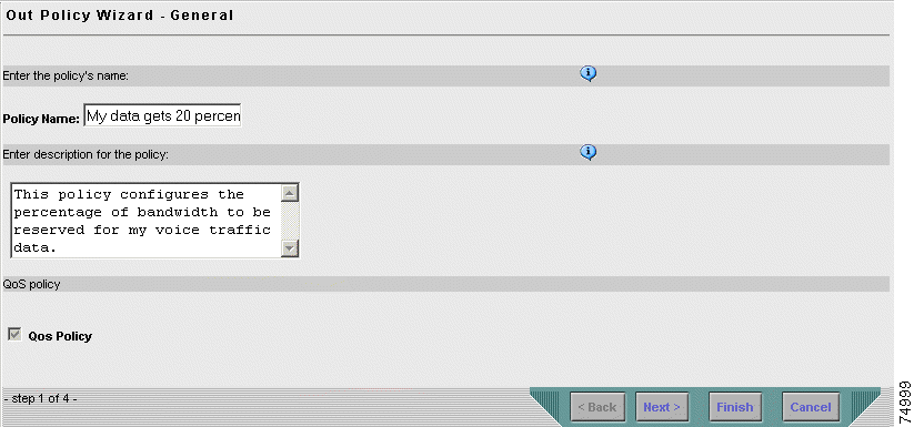
Step 4 Do the following in the Out Policy wizard - General page:
a. Enter My data gets 20 percent BW in the Policy Name field.
b. Enter This policy configures the percentage of bandwidth to be reserved for my voice traffic data in the description field.
c. Select the QoS Policy check box to define the type of policy you want to create.
d. Click Next. The Out Policy wizard - Filter page appears.
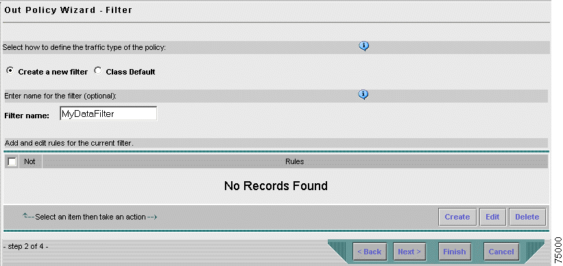
Step 5 Define a filter to specify the traffic to which the policy should be applied:
a. In the Out Policy wizard - Filter page, select the Create a new filter check box. This enables the policy to be applied to traffic that matches any of the filter conditions.
b. Enter MyDataFilter in the Filter name field.
c. Click Create. The Rule Setting page appears, displaying the conditions you can define for each filter rule.
Step 6 Define the condition for the filter rule:
a. In the Rule Setting page, click Edit next to the Service filter condition. The Service Editor dialog box opens.
b. From the Value list box, select 18 (af21)—the DSCP value of the packet. (For this example, it is assumed that data traffic was already marked at the edge.)
c. Click OK. The Service Editor dialog box closes, and the Rule Settings page refreshes to display the new Service condition.
d. Click Done. The Out Policy Wizard - Filter page reappears, displaying the filter rule you have defined.
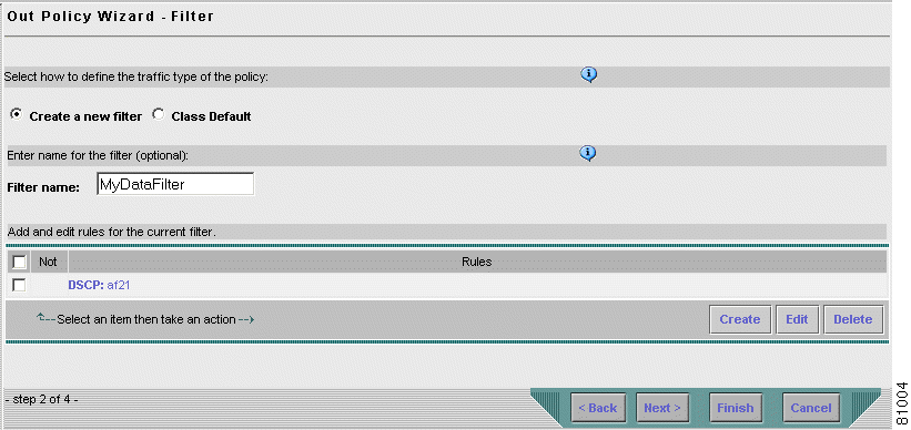
Step 7 Click Next in the Out Policy Wizard - Filter page. The Out Policy Wizard - Actions page for Marking appears.
Step 8 Define the QoS policy action:
a. Select Actions > Queuing in the wizard navigation TOC. The Out Policy Wizard - Queuing Actions page appears. (Queuing actions manage congestion for outbound traffic.)
b. Select the Enable Bandwidth Allocation (CBQ) check box.
c. Enter 20 in the Bandwidth field to define the percentage of the interface's bandwidth you want to allocate to your traffic.
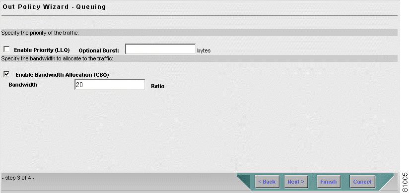
Step 9 Click Finish to complete the wizard. The Summary page appears.
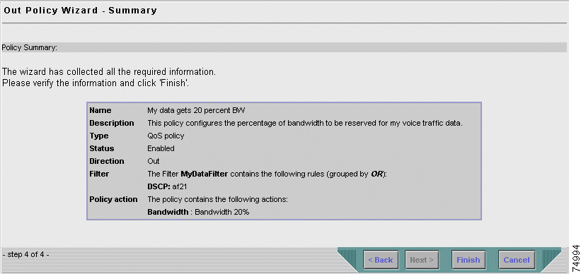
Step 10 In the Summary page, view the details of the QoS policy you defined. Then click Finish to complete the policy and exit the wizard.
The Out Policies page reappears, displaying the new policy you defined for the selected template.
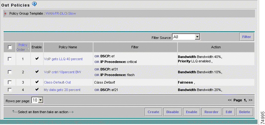
Since policies on an interface are executed top-down according to the list displayed in the table, they should appear in order of importance to ensure they get the required priority. In Figure 3-23, the Class Default policy precedes your new QoS policy. Since this policy is applied to all traffic that does not match any of the filters, you must reorder the policies so that it appears last in the list.
Step 11 Change the order of the policies in the policy group template:
a. Click Reorder in the Out Policies page. The Reorder Policies dialog box opens.
b. In the Reorder Policies dialog box, select My data gets 20 percent BW and click the Up button.
c. Click OK. The dialog box closes, and the Out Policies page reappears displaying the new policies order.
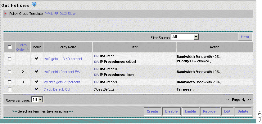
Step 12 Check that the QoS policy you defined in the WAN-FR-DLCI-Slow policy group template was also created in the attached voice policy group:
a. Select Configure > Policy Groups. The Policy Groups page appears.
b. Click the WAN-FR-DLCI-Slow voice policy group name in the table (you might need to open page 2 to find it). The General page appears.
c. In the Policy Group TOC, select Out Policies. The Out Policies page appears, displaying the newly defined QoS policy in the list with all the outbound policies for the WAN-FR-DLCI-Slow voice policy group.
Step 13 Continue with Lesson 3-3: Deploying the IP Telephony QoS Policies.
This lesson describes how to deploy the QoS policies that were saved in your deployment group to the devices in the network, where they will be implemented.
 |
Note Although you can follow all the steps in this lesson, the actual deployment of the "Tutorial" deployment group will fail, since you cannot deploy to virtual devices in the network. However, if you are using real devices in your IP telephony network, you should be able to deploy your QoS policies to your devices successfully. |
To distribute your QoS policies to your physical network devices, QPM translates your policies into device commands and enters the commands through the device's command line interface (CLI). You can choose whether or not to deploy your QoS configurations directly to the network devices using Telnet. QPM automatically deploys your QoS configurations to configuration files. This procedure does not configure your devices but generates configuration files that can be sent manually to the devices. QoS configurations can be deployed to the device using any application that downloads configuration files to the devices.
To do this lesson you should have completed Lesson 3-1: Assigning Voice Policies Using the IP Telephony Wizard.
Step 1 Select Deploy > Deployment. The first step of the Deployment wizard appears—Deployment Group Selection.
Step 2 Select the Current version of a deployment group radio button, and select Tutorial from the list box (if it isn't already selected).
Step 3 Click Next to move to the next step of the wizard—the Device Selection and Preview page.
This page displays a list of all the devices that are available for deployment. In this step of the wizard, you select the devices you want to deploy to. You can also preview your device configurations prior to deployment.
Step 4 If you are using virtual devices, select the check boxes next to the virtual devices in your IP Telephony network example. If you are using real devices, select the check boxes next to the devices to which you want to deploy your policies. Deselect those you do not want to deploy to.
Step 5 If you want to preview the CLI configuration commands for a device, click its configuration link in the table. A preview window opens, in which you can view the Backup ShowRun configuration commands and any incremental Telnet script commands that will be written to the device.
Step 6 After you have finished previewing the device's configuration, click Close to close the Preview window.
Step 7 Click Next to move to the next step of the wizard—the Job Details page.
Step 8 Enter IPT_Tutorial in the Job Name field.
Step 9 If required, you can enter a description for the job in the Job Description box.
Step 10 Make sure the Deploy configuration to the devices using Telnet check box is selected. (The configuration will also be saved to files.)
Step 11 Click Next to move to the final step of the wizard. This page presents a summary of the data collected through the wizard for you to verify.
Step 12 After you have verified the job information, click Deploy to deploy the deployment group to the network.
The Active Jobs page appears, enabling you to monitor the deployment process, as described in the next lesson.
QPM allows you to monitor the deployment process, by viewing the activity and status of your deployment job, in real-time. The Active Jobs page provides a dynamic view of all the currently active deployments and their status. For each job, the start time of configuration for each job, the job's status, and a summary of the number of devices deployed according to their status, is displayed.
The status of a job deployment or a device deployment may be Pending, In Progress, Completed, or Failed. A job deployment may also have the status of Aborted or Paused. For your deployment job to be "Completed", all the devices must be successfully configured. If the deployment of one device fails, the entire deployment fails.
To do this lesson you should have completed Lessons 3-1 and 3-3.
Step 1 Select Deploy > Jobs > Active Jobs.
The Active Jobs page appears, displaying your current deployment job and its status.
 |
Tip The display is automatically refreshed every ten seconds. You can refresh manually by clicking the Refresh button. |
Step 2 View the status of your deployment job.
During the deployment process, a status of In Progress will be displayed for your job. The status will change to Failed, since the devices in your network are virtual and you cannot deploy to virtual devices in a network.
 |
Note If you are using real devices in your network, the status should change to Completed, indicating that your deployment job was completed successfully. |
![]()
![]()
![]()
![]()
![]()
![]()
![]()
![]()
Posted: Tue Oct 15 08:31:24 PDT 2002
All contents are Copyright © 1992--2002 Cisco Systems, Inc. All rights reserved.
Important Notices and Privacy Statement.