|
|

This chapter shows you how to configure QoS on a data network using the provided virtual devices. QPM includes a file of virtual devices that you can import into the inventory to create this example network. By working with virtual devices, you can practice using QPM without the risk of working on live devices on your network.
If you have not yet imported the tutorial virtual devices and created the tutorial deployment group, see Lesson 1-2: Importing the Tutorial Virtual Devices and Lesson 1-4: Creating the Tutorial Deployment Group.
In lessons 2-1 through 2-5, you use QPM techniques and principles to configure QoS on specific segments of this network. In each lesson, a diagram clearly illustrates the relevant network segments, the data path, and the QoS features or policies applied. Lessons 2-6 and 2-7 describe how to deploy the QoS configurations you created in the previous lessons.
This chapter includes the following sections:
The following topics describe the data network tutorial example network and the scenarios on which the data network tutorial is based:
The data network tutorial is based on an example enterprise data network that consists of a campus site and two remote sites. Figure 2-1 shows the design of the example data network. Interfaces that do not have QoS applied to them in the tutorial are not labeled.
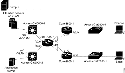
The campus site contains the following components:
The Finance remote site contains the following components:
The Finance users primarily require data from the application server and the FTP and web servers on the campus site. The primary path of data from these servers is from router Core-7200-1 on the campus site to remote router Core-3600-1.
The Sales remote site contains the following components:
The Sales users primarily communicate with the application and web servers on the campus site. The primary path of data from these servers to the Sales users is through router Core-7200-1 on the campus site to remote router Core-2600-1.
The following table provides the technical details of the devices in the example network shown in the preceding figure. Interfaces that do not have QoS applied to them in the tutorial are not listed.
| Device Name | Device Model and IP Address | Software Version | Interfaces | IP Address | Mask |
|---|---|---|---|---|---|
Core-7200-1 | 7204 | 12.2 | FastEthernet2/0 FastEthernet 100,000 Kbit/sec (100 Mb/sec) | 10.1.1.1 | 255.255.255.0 |
FastEthernet3/0 FastEthernet 100,000 Kbit/sec (100 Mb/sec) | 10.1.2.1 | 255.255.255.0 | |||
Serial4/0 T1 line at 1544 Kbit/second (PPP) | 10.2.2.1 | 255.255.255.0 | |||
Serial4/1 T1 line at 512 Kbit/second (PPP) | 10.2.3.1 | 255.255.255.0 | |||
Core-3600-1 | 3620 | 12.2 | FastEthernet0/0 FastEthernet 100,000 Kbit/sec (100 Mb/sec) | 10.3.1.1 | 255.255.255.0 |
Serial1/0 T1 line at 1544 Kbit/second (PPP) | 10.2.2.2 | 255.255.255.0 | |||
Core-2600-1 | 2621 | 12.2 | FastEthernet0/0 FastEthernet 100,000 Kbit/sec (100 Mb/sec) | 10.3.2.1 | 255.255.255.0 |
Serial1/0 T1 line at 512 Kbit/second (PPP) | 10.2.3.2 | 255.255.255.0 | |||
Access-Cat6000-1 | 6509 | 6.3 | SC0 [VLAN 20] | 10.1.1.2 | 255.255.255.0 |
Access-Cat6000-2 | 6509 | 6.3 | SC0 [VLAN 1] Ethernet 10,000 Kbit/sec (10 Mb/sec) | 10.1.2.2 | 255.255.255.0 |
Application (ERP) Server | 10.1.2.3 | — | — | — | 255.255.255.0 |
The goal of the data network tutorial is to guide you through the process of creating and deploying QoS policies to the sample network virtual devices. These policies are designed to achieve the goals of the following QoS scenarios.
The goal of scenario 1 is to color enterprise resource planning (ERP) traffic that originates from the Campus application servers so that the devices between these servers and the Sales and Finance users can provide good response time for these traffic types.
Implementing this scenario is described in the Lesson 2-1: Creating the Campus Access Cat6000 Port Policy Group.
The goal of scenario 2 is to color web traffic that originates from the Campus web server so that the devices between it and the Sales and Finance users can provide good response time for this traffic type.
Implementing this scenario is described in the Lesson 2-2: Defining Policy Groups and Policies To Color Campus Web Traffic.
The goal of scenario 3 is to color web and ERP traffic originating from the remote sites so that the devices between these sites and the Campus web and application servers can provide good response time for these traffic types.
Implementing this scenario is described in the Lesson 2-3: Creating the Remote FastEthernet Policy Group.
The goal of scenario 4 is to queue web and ERP traffic as it leaves the LAN and enters the WAN. This queuing ensures that each traffic type gets the desired percentage of the available bandwidth.
Implementing this scenario is described in Lesson 2-4: Creating the WAN PPP Policy Group.
The goal of scenario 5 is to police FTP traffic that originates from the Campus FTP server to limit its usage of network bandwidth.
Implementing this scenario is described in Lesson 2-5: Adding FTP Policing To the Campus Access VLAN Policy Group.
Now that you understand the data network tutorial network and scenarios, you are ready to proceed with the tutorial.
The lessons in this chapter use several QPM policy wizards to create the necessary policy groups and policies.
The following are some tips about how these wizards work:
The Campus Access Cat6000 Port policy group colors ERP traffic that originates from the Campus application server so that the devices between these servers and the Sales and Finance users can provide good response time for these traffic types. It is applied to the ingress interfaces of switch Access-Cat6000-2.
The details of the Campus Access Cat6000 Port policy group are as follows.
The following topics describe how to create the Campus Access VLAN policy group. Each step assumes that you have completed the previous step:
In this step you define the basic properties of the policy group, including:
Step 1 Select Configure > Policy Groups. The Policy Groups page appears.
Step 2 Select Tutorial from the Deployment Group list box.
The page refreshes to display the policy groups in the Tutorial deployment group. If you have not added any policy groups to the deployment group, the list is empty.
Step 3 Click Create. The Policy Group Definition wizard starts.
Step 4 Do the following in the Policy Group Definition Wizard - General Definition page:
a. Enter Campus Access Cat6000 Port in the Policy Group Name field.
b. Enter Colors inbound ERP traffic in the Policy Group Description field.
c. Do not modify the other page fields.
d. Click Next. The Policy Group Definition Wizard - Constraints Definition page appears.
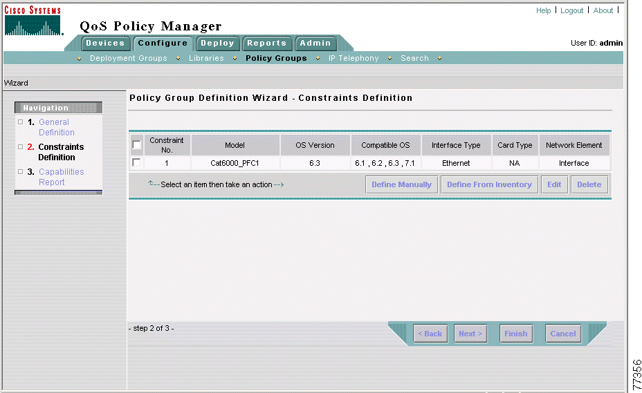
Step 5 Do the following in the Policy Group Definition Wizard - Constraints Definition page:
a. Click Define Manually. The Manual Constraint Definition page appears.
b. Select Cat6000_PFC1 from the Model list.
c. Select 6.3 from the OS Version list.
d. Select Interface from the Network Element Type list.
e. Select Ethernet from the Interface Type list.
f. Click OK. The Policy Group Definition Wizard - Constraints Definition page appears. Figure 2-2 shows the completed Policy Group Definition Wizard - Constraints Definition page.
Step 6 In the Policy Group Definition Wizard - Constraints Definition page, click Next.
The Policy Group Definition Wizard - Capabilities Report page appears, where you can view a summary of the QoS features that can be configured for the policy group, according to the device constraints.
Step 7 In the Policy Group Definition Wizard - Capabilities Report page, click Finish. The QoS Properties page appears.
Step 8 You have completed creation of the Campus Access Cat6000 Port policy group. Now you define its QoS properties. Continue with Step 2: Defining the Campus Access Cat6000 Port Policy Group QoS Properties.
This step assumes that you have completed Step 1: Defining the Campus Access Cat6000 Port Policy Group.
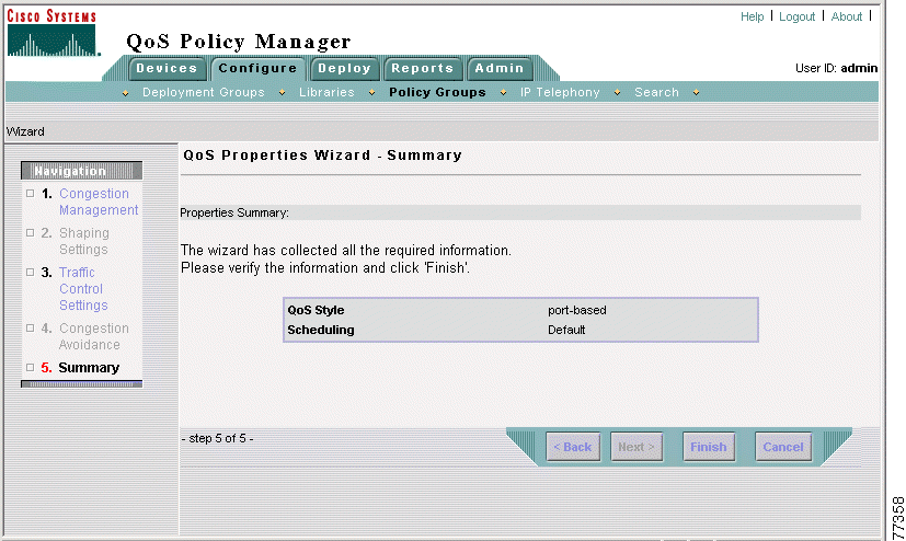
In this step you assign the QoS Style=Port Based property to the policy group. The policies in this policy group are defined for individual switch ports and not for the VLAN, therefore the QoS style must be set to port-based.
Step 1 In the QoS Properties page, click Edit. The QoS Properties Wizard - Congestion Management page appears.
 |
Note If the QoS Properties page is not open, select Configure > Policy Groups, then click the QoS Properties link for the Campus Access Cat6000 Port policy group. |
Step 2 In the QoS Properties Wizard - Congestion Management page, click Next to accept the page defaults. The QoS Properties Wizard - Traffic Control Settings page appears.
Step 3 In the QoS Properties Wizard - Traffic Control Settings page:
a. Select the Enable QoS Style check box.
b. Select the Port based radio button.
c. Do not modify the other page fields.
d. Click Finish. The QoS Properties Wizard - Summary page appears, where you can view a summary of the QoS properties for the policy group. Figure 2-3 shows the QoS Properties Wizard - Summary page.
Step 4 In the QoS Properties Wizard - Summary page, click Finish. The QoS Properties page appears.
Step 5 You have completed defining QoS properties for the Campus Access Cat6000 Port policy group. Now you assign elements to it. Continue with Step 3: Assigning Elements to the Campus Access Cat6000 Port Policy Group.
This step assumes that you have completed Step 2: Defining the Campus Access Cat6000 Port Policy Group QoS Properties.
In this step you assign the network element SC0 on switch Access-Cat6000-2 to the policy group.
Step 1 Select Assigned Network Elements in the TOC. The Assigned Network Elements page appears.
 |
Note If the Assigned Network Elements entry does not appear in the TOC, select Configure > Policy Groups, then click the Network Elements link for the Campus Access Cat6000 Port policy group. |
Step 2 In the Assigned Network Elements page, select Add. The Assignment dialog box opens.
Step 3 Do the following in the Assignment dialog box:
a. Select the network element sc0 on switch Access-Cat6000-2 by selecting the check box next to it.
b. Click Assign.
The dialog box closes. The selected network element appears in the Assigned Network Elements page.
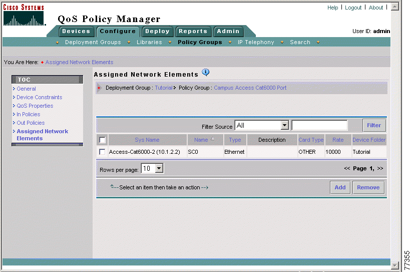
Step 4 You have completed assigning elements to the Campus Access Cat6000 Port policy group. Now you create the ERP Traffic Coloring policy. Continue with Step 4: Creating the ERP Traffic Coloring Policy.
This step assumes that you have completed Step 3: Assigning Elements to the Campus Access Cat6000 Port Policy Group.
In this step you create the ERP Traffic Coloring policy, which colors inbound ERP traffic to DSCP value 32.
Step 1 Select In Policies in the TOC. The In Policies page appears.
 |
Note If the In Policies entry does not appear in the TOC, select Configure > Policy Groups, then click the In Policies link for the Campus Access Cat6000 Port policy group. |
Step 2 In the In Policies page, click Create. The In Policy wizard opens, displaying the In Policy Wizard - General page.
Step 3 Do the following in the In Policy Wizard - General page:
a. Enter Color ERP traffic in the Policy Name field.
b. Enter Colors inbound ERP traffic in the Enter Description for the Policy field.
c. The QoS Policy check box is automatically selected.
d. Click Next. The In Policy Wizard - Filter page appears.
Step 4 Do the following in the In Policy Wizard - Filter page:
a. The New Filter check box is automatically selected.
b. Enter ERP traffic in the Filter name field.
c. Click Create to define a filter condition. The Rule Settings page appears.
Step 5 In the Rule Settings page, click Edit in the Protocol row of the Rule Setting table. The Protocol Editor dialog box opens.
Step 6 Do the following in the Protocol Editor dialog box:
a. Select the From Library radio button.
b. Select TCP from the Source list box.
c. Click OK. The Protocol Editor dialog box closes, and the Rule Settings page refreshes.
Step 7 In the Rule Settings page, click Edit in the Source IP row of the Rule Setting table. The Source IP Editor dialog box opens.
Step 8 Do the following in the Source IP Editor dialog box:
a. Select the IP Address / Host name list radio button.
b. Enter 10.1.2.3 (the IP address of the ERP server) in the IP/Host field.
c. Enter 255.255.255.0 in the Mask field.
d. Click Add. The address is added to the Add a new value list.
e. Click OK. The Source IP Editor dialog box closes and the Rule Setting page refreshes.
Step 9 In the Rule Setting page, click Done. The In Policy Wizard - Filter page appears.
Step 10 In the In Policy Wizard - Filter page, click Next. The In Policy Wizard - Marking page appears.
Step 11 Do the following in the In Policy Wizard - Marking page:
a. Select the Value radio button.
The Enable Marking check box is automatically selected.
b. Select 32 (cs4) from the Value list box.
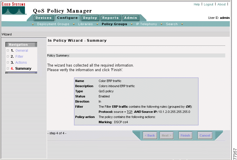
c. Click Finish. The In Policy Wizard - Summary page appears, where you can view a summary of the policy. Figure 2-5 shows the summary page.
Step 12 In the In Policy Wizard - Summary page, click Finish. The In Policies page appears.
Step 13 Select Configure > Policy Groups. The Policy Groups page appears.
Now that you have completed creating the Campus Access Cat6000 Port policy group to color ERP traffic that originates from the Campus application server, you can proceed with the next lesson, Lesson 2-2: Defining Policy Groups and Policies To Color Campus Web Traffic.
The goal of this lesson is to apply QoS that colors web traffic that originates from the Campus web server so that the devices between this server and the Sales and Finance users can provide good response time for web traffic.
You will apply this QoS to VLAN20 on switch Access-Cat6000-1. Coloring the traffic at this network location allows the switch to queue the traffic on the egress interfaces before sending the traffic to the WAN. Coloring at the switch is more desirable than coloring at the router between the switch and the WAN because the processing is distributed among more devices, conserving resources on the edge router.
To apply QoS to a VLAN in QPM, you must create two policy groups. The first policy group is assigned to the VLAN network element, and contains the QoS policies. The second policy group is assigned to the member interfaces of the VLAN, and defines the QoS style as VLAN-based.
Therefore, this lesson is divided into two lessons, one for each policy group:
The Campus Access VLAN policy group, in combination with the Campus Access VLAN Ports policy group, colors web traffic that originates from the Campus web server so that the devices between this server and the Sales and Finance users can provide good response time for web traffic. It is applied to the VLAN20 interface on switch Access-Cat6000-1.
The details of the Campus Access VLAN policy group are as follows:
The following topics describe how to create the Campus Access VLAN policy group. Each step assumes that you have just completed the previous step:
In this step you define the basic properties of the policy group, including:
Step 1 Select Configure > Policy Groups. The Policy Groups page appears.
Step 2 Select Tutorial from the Deployment Group list box. The page refreshes to display the policy groups in the Tutorial deployment group.
Step 3 Click Create. The Policy Group Definition wizard starts.
Step 4 Do the following in the Policy Group Definition Wizard - General Definition page:
a. Enter Campus Access VLAN in the Policy Group Name field.
b. Enter Colors outbound web traffic in the Policy Group Description field.
c. Do not modify the other page fields.
d. Click Next. The Policy Group Definition Wizard - Constraints Definition page appears.
Step 5 Do the following in the Policy Group Definition Wizard - Constraints Definition page:
a. Click Define Manually. The Manual Constraint Definition page appears.
b. Select Cat6000_PFC1 from the Model list.
c. Select 6.3 from the OS Version list.
d. Select VLAN from the Network Element Type list.
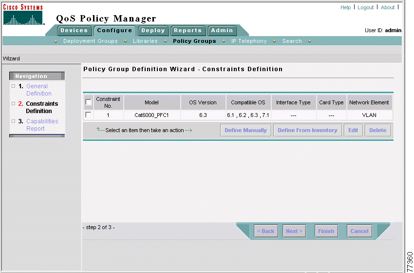
e. Click OK. The Policy Group Definition Wizard - Constraints Definition page appears. Figure 2-6 shows the completed Policy Group Definition Wizard - Constraints Definition page.
Step 6 In the Policy Group Definition Wizard - Constraints Definition page, click Next.
The Policy Group Definition Wizard - Capabilities Report page appears, where you can view a summary of the QoS features that can be configured for the policy group, according to the device constraints.
Step 7 In the Policy Group Definition Wizard - Capabilities Report page, click Finish. The QoS Properties page appears.
This policy group uses the default QoS properties, so there is no need to edit them.
Step 8 You have completed creation of the Campus Access VLAN Policy Group. Now assign network elements to it. Continue with Step 2: Assigning Elements to the Campus Access VLAN Policy Group.
This step assumes that you have completed Step 1: Defining the Campus Access VLAN Policy Group.
In this step you assign the network element VLAN20 on switch Access-Cat6000-1 to the policy group.
Step 1 Select Assigned Network Elements in the TOC. The Assigned Network Elements page appears.
 |
Note If the Assigned Network Elements entry does not appear in the TOC, select Configure > Policy Groups, then click the Network Elements link for the Campus Access VLAN policy group. |
Step 2 In the Assigned Network Elements page, select Add. The Assignment dialog box opens.
Step 3 Do the following in the Assignment dialog box:
a. Select the network element VLAN0020 on device Access-Cat6000-1 by selecting the check box next to it.
b. Click Assign.
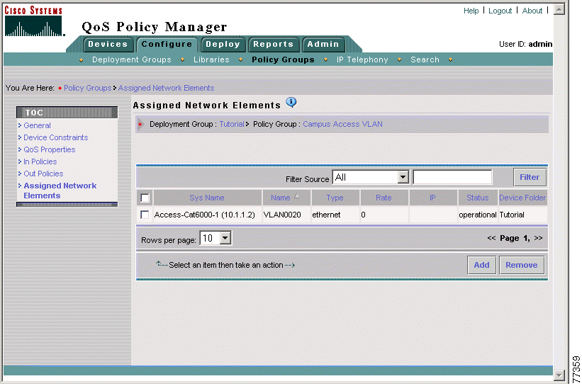
The dialog box closes. The selected network element appears in the Assigned Network Elements page. Figure 2-7 shows the completed Assigned Network Elements page.
Step 4 You have completed assigning elements to the Campus Access VLAN Policy Group. Now you create the Web Traffic Coloring policy. Continue with Step 3: Creating the Web Traffic Coloring Policy.
This step assumes that you have completed Step 2: Assigning Elements to the Campus Access VLAN Policy Group.
In this step you create the Web Traffic Coloring policy, which colors inbound web traffic to DSCP value 16.
Step 1 Select In Policies in the TOC. The In Policies page appears.
 |
Note If the In Policies entry does not appear in the TOC, select Configure > Policy Groups, then click the In Policies link for the Campus Access VLAN policy group. |
Step 2 In the In Policies page, click Create. The Policy wizard opens, displaying the In Policy Wizard - General page.
Step 3 Do the following In the In Policy Wizard - General page:
a. Enter Color web traffic in the Policy Name field.
b. Enter Colors web traffic in the Description field.
c. The QoS Policy check box is automatically selected.
d. Click Next. The In Policy Wizard - Filter page appears.
Step 4 Do the following in the In Policy Wizard - Filter page:
a. The New Filter check box is automatically selected.
b. Enter Web Traffic in the Filter Name field.
c. Click Create. The Rule Settings page appears.
Step 5 In the Rule Settings page, click Edit in the Protocol table row. The Protocol Editor dialog box opens.
Step 6 Do the following in the Protocol Editor dialog box:
a. Select the From Library radio button.
b. Select www-TCP from the Source list box.
c. Click OK. The Protocol Editor dialog box closes. The Rule Setting page updates in the main QPM window.
Step 7 In the Rule Settings page, click Done. The In Policy Wizard - Filter page appears.
Step 8 In the In Policy Wizard - Filter page, click Next. The In Policy Wizard - Marking page appears.
Step 9 Do the following in the In Policy Wizard - Marking page:
a. Select the Value radio button.
The Enable Marking check box is automatically selected.
b. Select 16 (cs2) from the Value list box.
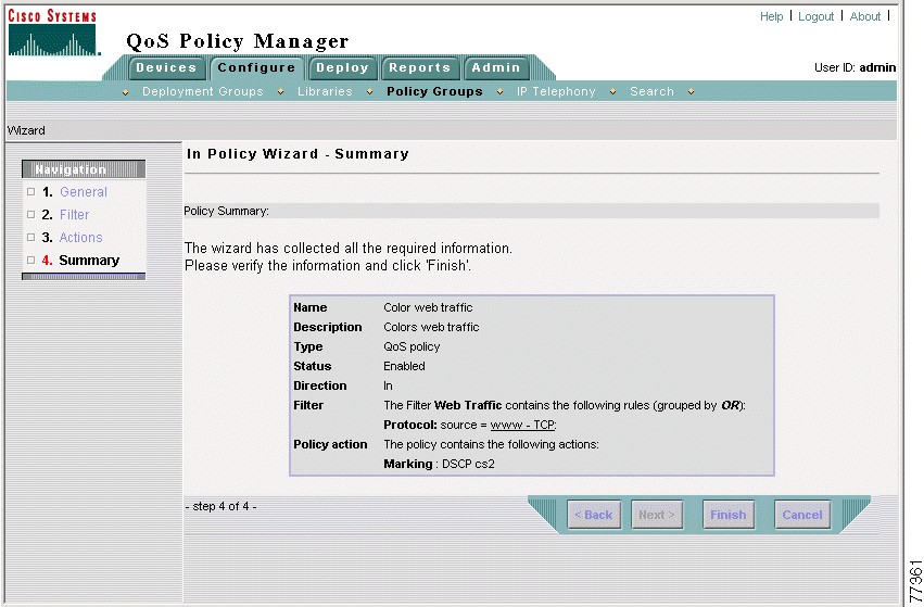
c. Click Finish. The In Policy Wizard - Summary page appears, where you can view a summary of the policy. Figure 2-8 shows the completed In Policy Wizard - Summary page.
d. Click Finish. The In Policies page appears.
Step 10 Select Configure > Policy Groups to open the Policy Groups page.
Now that you have completed creating the Campus Access VLAN policy group to color web traffic that originates from the Campus web server, you can proceed with the next lesson, Lesson 2-2-2: Defining the Campus Access VLAN Ports Policy Group.
The Campus Access VLAN Ports policy group, in combination with the Campus Access VLAN policy group, colors web traffic that originates from the Campus web server so that the devices between this server and the Sales and Finance users can provide good response time for web traffic. It is applied to the interfaces that are members of VLAN20 on switch Access-Cat6000-1.
This policy group defines the QoS style for its assigned ports as VLAN-based. This means that the VLAN policies in the Campus Access VLAN policy group will be deployed to these ports. Therefore this policy group does not contain any policies.
The details of the Campus Access VLAN policy group are as follows.
The following topics describe how to create the Campus Access VLAN Ports policy group. Each step assumes that you have just completed the previous step:
In this step you define the basic properties of the policy group, including:
Step 1 Select Configure > Policy Groups. The Policy Groups page appears.
Step 2 Select Tutorial from the Deployment Group list box. The page refreshes to display the policy groups in the Tutorial deployment group.
Step 3 Click Create. The Policy Group Definition wizard starts.
Step 4 Do the following in the Policy Group Definition Wizard - General Definition page:
a. Enter Campus Access VLAN Ports in the Policy Group Name field.
b. Enter Applies VLAN Based QoS Style in the Policy Group Description field.
c. Do not modify the other page fields.
d. Click Next. The Policy Group Definition Wizard - Constraints Definition page appears.
Step 5 Do the following in the Policy Group Definition Wizard - Constraints Definition page:
a. Click Define Manually. The Manual Constraint Definition page appears.
b. Select Cat6000_PFC1 from the Model list.
c. Select 6.3 from the OS Version list.
d. Select Interface from the Network Element Type list.
e. Select Ethernet from the Interface Type list.
f. Click OK. The Policy Group Definition Wizard - Constraints Definition page appears. Figure 2-9 shows the completed Policy Group Definition Wizard - Constraints Definition page.
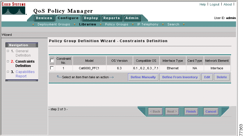
Step 6 In the Policy Group Definition Wizard - Constraints Definition page, click Next.
The Policy Group Definition Wizard - Capabilities Report page appears, where you can view a summary of the QoS features that can be configured for the policy group, according to the device constraints.
Step 7 In the Policy Group Definition Wizard - Capabilities Report page, click Finish. The QoS Properties page appears.
Step 8 You have completed creation of the Campus Access VLAN Ports policy group. Now you define its properties. Continue with Step 2: Defining the Campus Access VLAN Ports Policy Group QoS Properties.
This step assumes that you have completed Step 1: Defining the Campus Access VLAN Ports Policy Group.
In this step you assign the QoS Style=VLAN Based QoS property to the policy group.
Step 1 In the QoS Properties page, click Edit. The QoS Properties Wizard - Congestion Management page appears.
 |
Note If the QoS Properties page is not open, select Configure > Policy Groups, then click the QoS Properties link for the Campus Access VLAN Ports policy group. |
Step 2 In the QoS Properties Wizard - Congestion Management page, click Next to accept the page defaults. The QoS Properties Wizard - Traffic Control Settings page appears.
Step 3 Do the following in the QoS Properties Wizard - Traffic Control Settings page:
a. Select the Enable QoS Style check box.
b. Select the VLAN based radio button.
c. Do not modify the other page fields.
d. Click Next. The QoS Properties Wizard - Summary page appears. Figure 2-10 shows the QoS Properties Wizard - Summary page.
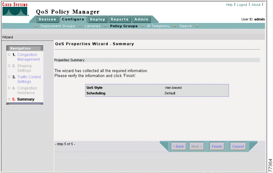
Step 4 In the QoS Properties Wizard - Summary page, click Finish. The QoS Properties page appears.
Step 5 You have completed defining the QoS properties of the Campus Access VLAN Ports policy group. Now you assign network elements to it. Continue with Step 3: Assigning Elements to the Campus Access VLAN Ports Policy Group.
This step assumes that you have completed Step 2: Defining the Campus Access VLAN Ports Policy Group QoS Properties.
In this step you assign the interfaces that are assigned to VLAN20 on switch Access-Cat6000-1 to the policy group.
Step 1 Select Assigned Network Elements in the TOC. The Assigned Network Elements page appears.
 |
Note If the Assigned Network Elements entry does not appear in the TOC, select Configure > Policy Groups, then click the Network Elements link for the Campus Access VLAN Ports policy group. |
Step 2 In the Assigned Network Elements page, select Add. The Assignment dialog box opens.
Step 3 Do the following in the Assignment dialog box:
a. Select the network element sc0 on device Access-Cat6000-1 by selecting the check box next to it.
b. Click Assign.
The dialog box closes. The selected network element appears in the Assigned Network Elements page. Figure 2-11 shows the completed Assigned Network Elements page.
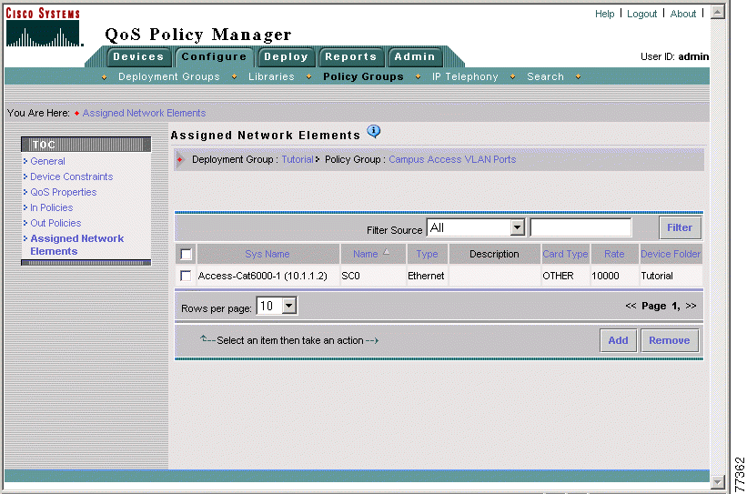
Now that you have completed defining policy groups and policies to color campus web traffic, you can proceed with the next lesson, Lesson 2-3: Creating the Remote FastEthernet Policy Group.
The Remote FastEthernet policy group colors web and ERP traffic originating from the remote sites so that the devices between these sites and the Campus web and application servers can provide good response time for these traffic types. It is applied to the ingress FastEthernet interfaces of routers Core-3600-1 and Core-2600-1.
Coloring this traffic at these interfaces allows the routers to queue these traffic types on the egress interfaces (based on color) before sending the traffic to the WAN. This policy group is necessary because the switches at the remote sites cannot color traffic, so the coloring must be done at the routers.
The details of the Remote FastEthernet policy group are as follows.
The following topics describe how to create the Remote FastEthernet policy group. Each step assumes that have just completed the previous step:
In this step you define the basic properties of the policy group, including:
Step 1 Select Configure > Policy Groups. The Policy Groups page appears.
Step 2 Select Tutorial from the Deployment Group list box. The page refreshes to display the policy groups in the Tutorial deployment group.
Step 3 Click Create. The Policy Group Definition wizard starts.
Step 4 Do the following in the Policy Group Definition Wizard - General Definition page:
a. Enter Remote FastEthernet in the Policy Group Name field.
b. Enter Colors web and ERP traffic from remote sites in the Policy Group Description field.
c. Do not modify the other page fields.
d. Click Next. The Policy Group Definition Wizard - Constraints Definition page appears.
Step 5 Do the following in the Policy Group Definition Wizard - Constraints Definition page:
a. Click Define Manually. The Manual Constraint Definition page appears.
b. Select 2600 from the Model list.
c. Select 12.2 from the OS Version list.
d. Select Interface from the Network Element Type list.
e. Select Ethernet from the Interface Type list.
f. Click OK. The Policy Group Definition Wizard - Constraints Definition page appears.
Step 6 Do the following in the Policy Group Definition Wizard - Constraints Definition page:
a. Click Define Manually. The Manual Constraint Definition page appears.
b. Select 3600 from the Model list.
c. Select 12.2 from the OS Version list.
d. Interface is automatically entered in the Network Element Type list.
e. Select Ethernet from the Interface Type list.
f. Click OK. The Policy Group Definition Wizard - Constraints Definition page appears. Figure 2-12 shows the completed Policy Group Definition Wizard - Constraints Definition page.
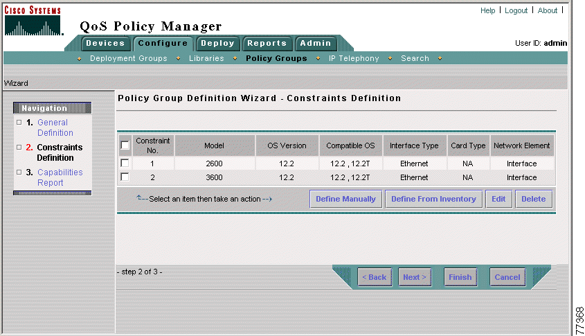
Step 7 In the Policy Group Definition Wizard - Constraints Definition page, click Next.
The Policy Group Definition Wizard - Capabilities Report page appears, where you can view a summary of the QoS features that can be configured for the policy group, according to the device constraints.
Step 8 In the Policy Group Definition Wizard - Capabilities Report page, click Finish. The QoS Properties page appears.
Step 9 You have completed creation of the Remote FastEthernet policy group. Now you define its QoS properties. Continue with Step 2: Defining the Remote FastEthernet Policy Group QoS Properties.
This step assumes that you have completed Step 1: Defining the Remote FastEthernet Policy Group.
In this step you define the Class-based QoS property to the policy group.
Step 1 In the QoS Properties page, click Edit. The QoS Properties Wizard - Congestion Management page appears.
 |
Note If the QoS Properties page is not open, select Configure > Policy Groups, then click the QoS Properties link for the Remote FastEthernet policy group. |
Step 2 Do the following in the QoS Properties Wizard - Congestion Management page:
a. Select Class Based QoS from the Select a scheduling method list box.
b. Click Finish. The QoS Properties Wizard - Summary page appears. Figure 2-13 shows the QoS Properties Wizard - Summary page.
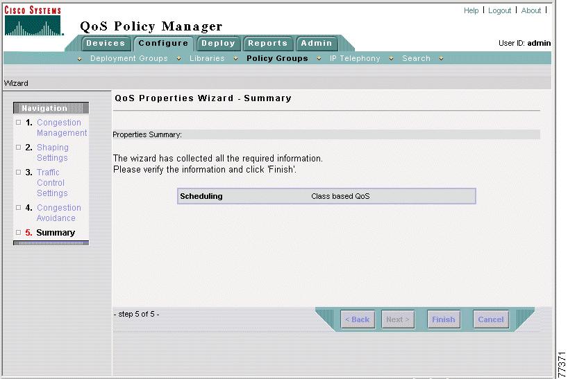
Step 3 In the QoS Properties Wizard - Summary page, click Finish. The QoS Properties page appears.
Step 4 You have defined the QoS properties of the Remote FastEthernet policy group. Now you assign network elements to it. Continue with Step 3: Assigning Elements to the Campus Access Cat6000 Port Policy Group.
This step assumes that you have completed Step 2: Defining the Remote FastEthernet Policy Group QoS Properties.
In this step you assign these network elements to the policy group:
Step 1 Select Assigned Network Elements in the TOC. The Assigned Network Elements page appears.
 |
Note If the Assigned Network Elements entry does not appear in the TOC, select Configure > Policy Groups, then click the Network Elements link for the Remote FastEthernet policy group. |
Step 2 In the Assigned Network Elements page, select Add. The Add Assignment dialog box opens.
Step 3 Do the following in the Add Assignment dialog box:
a. Select the following network elements by selecting the check box next to them.
b. Click Assign.
The dialog box closes. The selected network element appears in the Assigned Network Elements page. Figure 2-14 shows the completed Assigned Network Elements page.
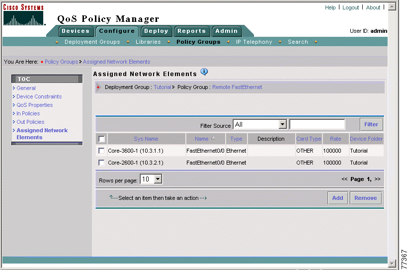
Step 4 You have completed assigning network elements to the Remote FastEthernet policy group. Now you create the Web Traffic Coloring policy. Continue with Step 4: Creating the Web Traffic Coloring Policy.
This step assumes that you have completed Step 3: Assigning Elements to the Remote FastEthernet Policy Group.
In this step you create the Web Traffic Coloring policy, which colors web traffic coming from the remote sites to DSCP 16.
Step 1 Select In Policies in the TOC. The In Policies page appears.
 |
Note If the In Policies entry does not appear in the TOC, select Configure > Policy Groups, then click the In Policies link for the Remote FastEthernet policy group. |
Step 2 In the In Policies page, click Create. The In Policy wizard opens, displaying the In Policy Wizard - General page.
Step 3 Do the following in the In Policy Wizard - General page:
a. Enter Web Traffic Coloring in the Policy Name field.
b. Enter Colors inbound web traffic in the Enter Description for the Policy field.
c. Leave the QoS Policy radio button selected.
d. Click Next. The In Policy Wizard - Filter page appears.
Step 4 Do the following in the In Policy Wizard - Filter page:
a. Leave the Create a new filter radio button selected.
b. Enter Web traffic in the Filter name field.
c. Click Create to define a filter rule. The Rule Settings page appears.
Step 5 In the Rule Settings page, click Edit in the Protocol table row. The Protocol Editor dialog box opens.
Step 6 Do the following in the Protocol Editor dialog box:
a. Select the From Library radio button.
b. Select www-TCP from the Source list box.
c. Click OK. The Protocol Editor dialog box closes. The Rule Setting page updates in the main QPM window.
Step 7 In the Rule Settings page, click Done. The In Policy Wizard - Filter page appears.
Step 8 In the In Policy Wizard - Filter page, click Next. The In Policy Wizard - Marking page appears.
Step 9 Do the following in the In Policy Wizard - Marking page:
a. Select 16 (cs2) from the Value list box.
The Enable Marking check box is automatically selected.
b. Click Finish. The In Policy Wizard - Summary page appears, where you can view a summary of the policy. Figure 2-15 shows the completed In Policy Wizard - Summary page.
c. Click Finish. The In Policies page appears.
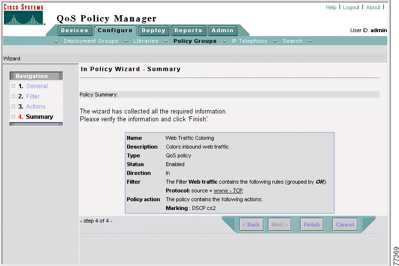
Step 10 You have completed creation of the Web Traffic Coloring policy. Continue with Step 5: Creating the ERP Traffic Coloring Policy.
This step assumes that you have completed Step 4: Creating the Web Traffic Coloring Policy.
In this step you create the ERP Traffic Coloring policy, which colors ERP traffic coming from the remote sites to DSCP 32.
Step 1 In the In Policies page, click Create. The In Policy wizard opens, displaying the In Policy Wizard - General page.
 |
Note If the In Policies entry does not appear in the TOC, select Configure > Policy Groups, then click the In Policies link for the Remote FastEthernet policy group. |
Step 2 Do the following in the In Policy Wizard - General page:
a. Enter Color ERP traffic in the Policy Name field.
b. Enter Colors inbound ERP traffic in the Enter Description for the Policy field.
c. Leave the QoS Policy check box selected.
d. Click Next. The In Policy Wizard - Filter page appears.
Step 3 Do the following in the In Policy Wizard - Filter page:
a. The Create a new filter check box is automatically selected.
b. Enter ERP traffic in the Filter name field.
c. Click Create to define a filter condition. The Rule Settings page appears.
Step 4 In the Rule Settings page, click Edit in the Protocol row of the Rule Setting table. The Protocol Editor dialog box opens.
Step 5 Do the following in the Protocol Editor dialog box:
a. Select the From Library radio button.
b. Select TCP from the Source list box.
c. Click OK. The Protocol Editor dialog box closes, and the Rule Settings page refreshes.
Step 6 In the Rule Settings page, click Edit in the Destination IP row of the Rule Setting table. The Destination IP Editor dialog box opens.
Step 7 Do the following in the Destination IP Editor dialog box:
a. Select the IP Address/Host name list radio button.
b. Enter 10.1.2.3 (the IP address of the ERP server) in the IP/Host field.
c. Enter 255.255.255.0 in the Mask field.
d. Click Add. The address is added to the Add a new value list.
e. Click OK. The Destination IP Editor dialog box closes and the Rule Setting page refreshes.
Step 8 In the Rule Setting page, click Done. The In Policy Wizard - Filter page appears.
Step 9 In the In Policy Wizard - Filter page, click Next. The In Policy Wizard - Marking page appears.
Step 10 Do the following in the In Policy Wizard - Marking page:
a. Select 32 (cs4) from the Value list box.
The Enable Marking check box is automatically selected.
b. Click Finish. The In Policy Wizard - Summary page appears, where you can view a summary of the policy. Figure 2-16 shows the completed In Policy Wizard - Summary page.
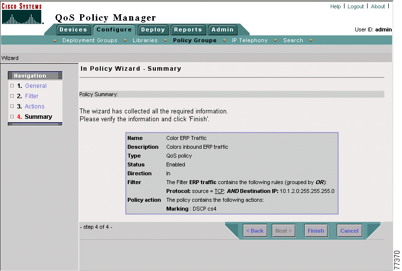
Step 11 In the In Policy Wizard - Summary page, click Finish. The In Policies page appears.
Step 12 Select Configure > Policy Groups. The Policy Groups page appears.
Now that you have completed creating the Remote FastEthernet policy group to color web and ERP traffic originating from the remote sites, you can proceed with the next lesson, Lesson 2-4: Creating the WAN PPP Policy Group.
The WAN PPP policy group queues web and ERP traffic that is exchanged between the web and application servers on the Campus and the remote Finance and Sales groups. It is applied to the egress interfaces of the core routers—Core-7200-1, Core-3600-1, and Core-2600-1.
These interfaces are the best network elements on which to apply queuing because they connect the Campus and remote LANs to the WAN. The bandwidth difference between the LAN and WAN creates a backlog of traffic at these interfaces, so a queuing policy will ensure that web and ERP traffic flows get the desired share of the available WAN bandwidth.
Only one queuing policy group is necessary because one policy group with the necessary properties and policies can be applied to all of the pertinent interfaces. This is unlike the situation with the coloring policy, in which two policy groups are necessary because coloring is applied at switch interfaces on the Campus LAN, but is applied at router interfaces on the remote LANs.
The details of the WAN PPP policy group are as follows.
The following topics describe how to create the WAN PPP policy group. Each step assumes that have just completed the previous step:
In this step you define the basic properties of the policy group, including:
Step 1 Select Configure > Policy Groups. The Policy Groups page appears.
Step 2 Select Tutorial from the Deployment Group list box. The page refreshes to display the policy groups in the Tutorial deployment group.
Step 3 Click Create. The Policy Group Definition wizard starts.
Step 4 Do the following in the Policy Group Definition Wizard - General Definition page:
a. Enter WAN PPP in the Policy Group Name field.
b. Enter Applies MQC CBWFQ to ERP and web traffic entering the WAN in the Policy Group Description field.
c. Do not modify the other page fields.
d. Click Next. The Policy Group Definition Wizard - Constraints Definition page appears.
Step 5 In the Policy Group Definition Wizard - Constraints Definition page, click Define Manually. The Manual Constraint Definition page appears.
Step 6 Do the following in the Manual Constraint Definition page:
a. Select 2600 from the Model list.
b. Select 12.2 from the OS Version list.
c. Select Interface from the Network Element Type list.
d. Select PPP from the Interface Type list.
e. Click OK. The Policy Group Definition Wizard - Constraints Definition page appears.
Step 7 In the Policy Group Definition Wizard - Constraints Definition page, click Define Manually. The Manual Constraint Definition page appears.
Step 8 Do the following in the Manual Constraint Definition page:
a. Select 3600 from the Model list.
b. Select 12.2 from the OS Version list.
c. Interface is automatically entered in the Network Element Type field.
d. Select PPP from the Interface Type list.
e. Click OK. The Policy Group Definition Wizard - Constraints Definition page appears.
Step 9 In the Policy Group Definition Wizard - Constraints Definition page, click Define Manually. The Manual Constraint Definition page appears.
Step 10 Do the following in the Manual Constraint Definition page:
a. Select 7200 from the Model list.
b. Select 12.2 from the OS Version list.
c. Interface is automatically entered in the from the Network Element Type field.
d. Select PPP from the Interface Type list.
e. Click OK. The Policy Group Definition Wizard - Constraints Definition page appears. Figure 2-17 shows the completed Policy Group Definition Wizard - Constraints Definition page.
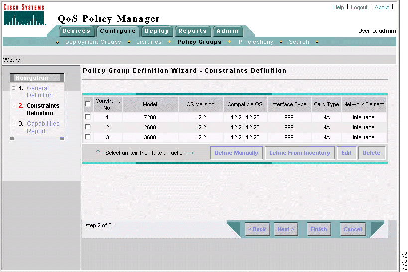
Step 11 In the Policy Group Definition Wizard - Constraints Definition page, click Next.
The Policy Group Definition Wizard - Capabilities Report page appears, where you can view a summary of the QoS features that can be configured for the policy group, according to the device constraints.
Step 12 In the Policy Group Definition Wizard - Capabilities Report page, click Finish. The QoS Properties page appears.
Step 13 You have completed creation of the WAN PPP policy group. Now you define its QoS properties. Continue with Step 2: Defining the WAN PPP Policy Group QoS Properties.
This step assumes that you have completed Step 1: Defining the WAN PPP Policy Group.
In this step you assign the modular QoS CLI (MQC) class-based weighted fair queuing (CBWFQ) QoS property to the policy group.
Step 1 In the QoS Properties page, click Edit. The QoS Properties Wizard - Congestion Management page appears.
 |
Note If the QoS Properties page is not open, select Configure > Policy Groups, then click the QoS Properties link for the WAN PPP policy group. |
Step 2 Do the following in the QoS Properties Wizard - Congestion Management page:
a. Select Class Based QoS from the Select a scheduling method list box.
b. Click Finish. The QoS Properties Wizard - Summary page appears. Figure 2-18 shows the QoS Properties Wizard - Summary page.
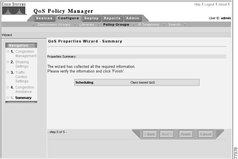
Step 3 In the QoS Properties Wizard - Summary page, click Finish. The QoS Properties page appears.
Step 4 You have completed defining QoS properties for the WAN PPP policy group. Now you assign network elements to it. Continue with Step 3: Assigning Elements to the WAN PPP Policy Group.
This step assumes that you have completed Step 2: Defining the WAN PPP Policy Group QoS Properties.
In this step you assign these network elements to the policy group:
Step 1 Select Assigned Network Elements in the TOC. The Assigned Network Elements page appears.
 |
Note If the Assigned Network Elements entry does not appear in the TOC, select Configure > Policy Groups, then click the Network Elements link for the WAN PPP policy group. |
Step 2 In the Assigned Network Elements page, select Add. The Assignment dialog box opens.
Step 3 Do the following in the Assignment dialog box:
a. Select the following network elements by selecting the check box next to them.
b. Click Assign.
The dialog box closes. The selected network element appears in the Assigned Network Elements page. Figure 2-19 shows the completed Assigned Network Elements page.
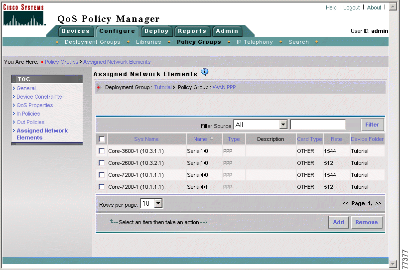
Step 4 You have completed assigning network elements to the WAN PPP policy group. Now you create the MQC CBWFQ queuing policies. Continue with Step 4: Creating the MQC CBWFQ Queuing Policies.
In this step you create the three policies that are needed to apply MQC CBWFQ queuing to web and ERP traffic entering the WAN, and implement a class default policy for all traffic that does not match any of the traffic classes:
The following sections describe how to create these policies:
This step assumes that you have completed Step 3: Assigning Elements to the WAN PPP Policy Group.
In this step you create the ERP Traffic Queuing policy, which queues ERP traffic entering the WAN using MCQ CBWFQ. It works in conjunction with the DSCP marking that is done by other policies to allocate 40% of the link bandwidth to DSCP 32 (ERP) traffic.
Step 1 Select Out Policies in the TOC. The Out Policies page appears.
 |
Note If the Out Policies entry does not appear in the TOC, select Configure > Policy Groups, then click the Out Policies link for the WAN PPP policy group. |
Step 2 In the Out Policies page, click Create. The Out Policy wizard opens, displaying the Out Policy Wizard - General page.
Step 3 Do the following in the Out Policy Wizard - General page:
a. Enter ERP Traffic Queuing in the Policy Name field.
b. Enter Queues ERP traffic entering the WAN in the Enter Description for the Policy field.
c. Leave the QoS Policy radio button selected.
d. Click Next. The Out Policy Wizard - Filter page appears.
Step 4 Do the following in the Out Policy Wizard - Filter page:
a. Leave the Create a new filter radio button selected.
b. Enter ERP Traffic in the Filter Name field.
c. Click Create. The Rule Setting page appears.
Step 5 In the Rule Setting page, click Edit in the Service table row. The Service Editor dialog box opens.
Step 6 Do the following in the Service Editor dialog box:
a. Select 32 (cs4) from the Value list box.
b. Click OK. The Service Editor dialog box closes, and the Rule Settings page refreshes.
Step 7 In the Rule Settings page, click Done. The Out Policy Wizard - Filter page appears.
Step 8 In the Out Policy Wizard - Filter page, click Next. The Out Policy Wizard - Marking page appears.
Step 9 Click Queuing in the Navigation list (under step 3, Actions). The Out Policy Wizard - Queuing page appears.
Step 10 Do the following in the Out Policy Wizard - Queuing page:
a. Enter 40 in the bandwidth field.
The Enable Bandwidth Allocation (CBQ) check box is automatically selected.
b. Leave the Ratio radio button selected.
c. Click Finish. The Out Policy Wizard - Summary page appears, where you can view a summary of the policy. Figure 2-20 shows the completed Out Policy Wizard - Summary page.
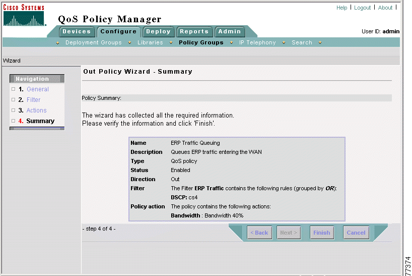
Step 11 In the Out Policy Wizard - Summary page, click Finish. The Out Policies page appears.
Step 12 You have completed creating the ERP Traffic Queuing policy. Now you create the Web Traffic Queuing policy. Continue with Step 4b: Creating the Web Traffic Queuing Policy.
This step assumes that you have completed Step 4a: Creating the ERP Traffic Queuing Policy.
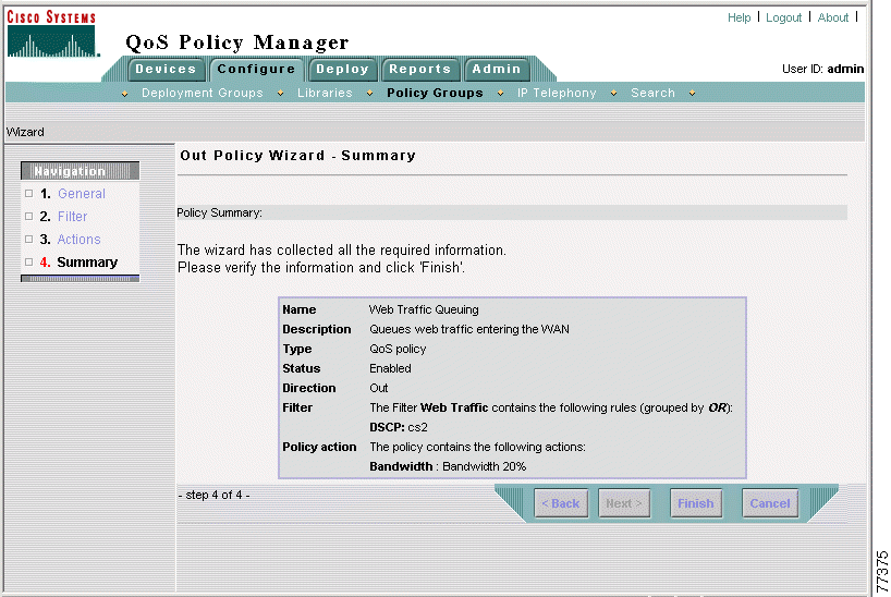
In this step you create the Web Traffic Queuing policy, which queues web traffic entering the WAN using MCQ CBWFQ. It works in conjunction with the DSCP marking that is done by other policies to allocate 20% of the link bandwidth to DSCP 16 (web) traffic.
Step 1 In the Out Policies page, click Create. The Out Policy wizard opens, displaying the Out Policy Wizard - General page.
 |
Note If the Out Policies page is not open and the Out Policies entry does not appear in the TOC, select Configure > Policy Groups, then click the Out Policies link for the WAN PPP policy group. |
Step 2 Do the following in the Out Policy Wizard - General page:
a. Enter Web Traffic Queuing in the Policy Name field.
b. Enter Queues web traffic entering the WAN in the Enter Description for the Policy field.
c. Leave the QoS Policy radio button selected.
d. Click Next. The Out Policy Wizard - Filter page appears.
Step 3 Do the following in the Out Policy Wizard - Filter page:
a. Leave the Create a new filter radio button selected.
b. Enter Web Traffic in the Filter Name field.
c. Click Create. The Rule Setting page appears.
Step 4 In the Rule Setting page, click Edit in the Service table row. The Service Editor dialog box opens.
Step 5 Do the following in the Service Editor dialog box:
a. Select 16 (cs2) from the Value list box.
b. Click OK. The Service Editor dialog box closes, and the Rule Settings page refreshes.
Step 6 In the Rule Settings page, click Done. The Out Policy Wizard - Filter page appears.
Step 7 In the Out Policy Wizard - Filter page, click Next. The Out Policy Wizard - Marking page appears.
Step 8 Click Queuing in the Navigation list (under step 3, Actions). The Out Policy Wizard - Queuing page appears.
Step 9 Do the following in the Out Policy Wizard - Queuing page:
a. Enter 20 in the bandwidth field.
The Enable Bandwidth Allocation (CBQ) check box is automatically selected.
b. Click Finish. The Out Policy Wizard - Summary page appears, where you can view a summary of the policy. Figure 2-21 shows the completed Out Policy Wizard - Summary page.
Step 10 In the Out Policy Wizard - Summary page, click Finish. The Out Policies page appears.
Step 11 You have completed creating the Web Traffic Queuing policy. Now you create the Class Default policy. Continue with Step 4c: Creating the Class Default Policy.
This step assumes that you have completed Step 4b: Creating the Web Traffic Queuing Policy.
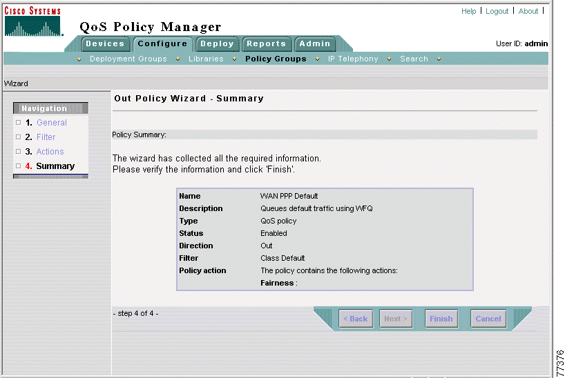
In this step you create the class default policy, which assigns weighted fair queuing (WFQ) as the queuing method for all traffic that does not match the filters of the other policies.
Step 1 In the Out Policies page, click Create. The Out Policy wizard opens, displaying the Out Policy Wizard - General page.
 |
Note If the Out Policies page is not open and the Out Policies entry does not appear in the TOC, select Configure > Policy Groups, then click the Out Policies link for the WAN PPP policy group. |
Step 2 Do the following in the Out Policy Wizard - General page:
a. Enter WAN PPP Default in the Policy Name field.
b. Enter Queues default traffic using WFQ in the Enter Description for the Policy field.
c. Leave the QoS Policy radio button selected.
d. Click Next. The Out Policy Wizard - Filter page appears.
Step 3 Do the following in the Out Policy Wizard - Filter page:
a. Click the Class Default radio button.
b. Click Next. The Out Policy Wizard - Marking page appears.
Step 4 Click Queuing in the Navigation list (under step 3, Actions). The Out Policy Wizard - Queuing page appears.
Step 5 Do the following in the Out Policy Wizard - Actions page:
a. Select the Enable WFQ check box.
b. Click Finish. The Out Policy Wizard - Summary page appears, where you can view a summary of the policy. Figure 2-22 shows the completed Out Policy Wizard - Summary page.
Step 6 In the Out Policy Wizard - Summary page, click Finish. The Out Policies page appears.
Now that you have completed creating the WAN PPP policy group to queue web and ERP traffic that is exchanged between the web and application servers on the Campus and the remote Finance and Sales groups, you can proceed with the next lesson, Lesson 2-5: Adding FTP Policing To the Campus Access VLAN Policy Group.
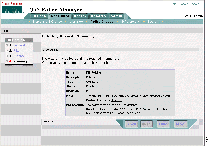
This lesson demonstrates how you can add additional functionality to an existing policy group. In this case, you will add a policing policy to police FTP traffic, limiting FTP bandwidth usage to 128 Kbps, to the Campus Access VLAN policy group.
This lesson assumes that you have completed Lesson 2-2: Defining Policy Groups and Policies To Color Campus Web Traffic.
Step 1 Select Configure > Policy Groups. The policy groups page appears.
Step 2 Select Tutorial from the Deployment Group list box.
Step 3 Click the number in the In Policies column of the of the Campus Access VLAN policy group table entry. The In Policies page appears.
Step 4 In the In Policies page, click Create. The In Policy Wizard - General page appears.
Step 5 Do the following in the In Policy Wizard - General page:
a. Enter FTP Policing in the Policy Name field.
b. Enter Polices FTP traffic in the Enter Description for the Policy field.
c. Click Next. The In Policy Wizard - Filter page appears.
Step 6 Do the following in the In Policy Wizard - Filter page:
a. The New Filter check box is automatically selected.
b. Enter FTP Traffic in the Filter name field.
c. Click Create. The Rule Setting page appears.
Step 7 In the Rule Setting page, click Edit in the Protocol table row. The Protocol Editor dialog box opens.
Step 8 Do the following in the Protocol Editor dialog box:
a. Leave the From Library radio button selected.
b. Select ftp-TCP from the Source list box.
c. Click OK. The Service Editor dialog box closes, and the Rule Settings page refreshes.
Step 9 In the Rule Settings page, click Done. The In Policy Wizard - Filter page appears.
Step 10 In the In Policy Wizard - Filter page, click Next. The In Policy Wizard - Marking page appears.
Step 11 Select Policing in the Navigation list (under step 3, Actions). The In Policy Wizard - Policing page appears.
Step 12 Do the following in the In Policy Wizard - Policing page:
a. Select the Aggregate radio button.
The Enable Policing check box is automatically selected.
b. Enter 128 in the Rate field.
c. Enter 128 in the Burst field.
d. Select Mark and Transmit from the Conform Action list box.
e. Select 0 (default) from the Mark with list box.
f. Select Drop from the Exceed Action list box.
g. Click Finish. The In Policy Wizard - Summary page appears, where you can view a summary of the policy. Figure 2-23 shows the completed In Policy Wizard - Summary page.
Step 13 In the In Policy Wizard - Summary page, click Finish. The In Policies page appears.
Step 14 Select Configure > Policy Groups. The Policy Groups page appears.
Now that you have added FTP policing to the Campus Access VLAN policy group, you can proceed with the next lesson, Lesson 2-6: Deploying the Data Network Tutorial Policies.
This lesson describes how to deploy the QoS policies that were saved in your deployment group to the devices in the network, where they will be implemented.
 |
Note Although you can follow all the steps in this lesson, the actual deployment of the "Tutorial" deployment group will fail, since you cannot deploy to virtual devices in the network. However, if you are using real devices in your data network, you should be able to deploy your QoS policies to your devices successfully. |
To distribute your QoS policies to your physical network devices, QPM translates your policies into device commands and enters the commands through the device's command line interface (CLI). You can choose whether or not to deploy your QoS configurations directly to the network devices through Telnet. QPM automatically deploys your QoS configurations to configuration files. This procedure does not configure your devices but generates configuration files that can be sent manually to the devices. QoS configurations can be deployed to the device through any application that downloads configuration files to the devices.
To do this lesson you should have completed lessons 2-1 through 2-5.
Step 1 Select Deploy > Deployment. The first step of the Deployment wizard is displayed—Deployment Group Selection.
Step 2 Select the Current version of a deployment group radio button, and select Tutorial from the list box (if it isn't already selected).
Step 3 Click Next to move to the next step of the wizard—the Device Selection and Preview page.
This page displays a list of all the devices that are available for deployment. In this step of the wizard, you select the devices you want to deploy to. You can also preview your device configurations prior to deployment.
Step 4 If you are using virtual devices, select the check boxes next to the virtual devices in your data network example. If you are using real devices, select the check boxes next to the devices to which you want to deploy your policies. Deselect those you do not want to deploy to.
Step 5 If you want to preview the CLI configuration commands for a device, click its configuration link in the table. A preview window opens, letting you view the Backup ShowRun configuration commands and any incremental Telnet script commands that will be written to the device.
Step 6 When you have finished previewing the device's configuration, click Close to close the Preview window.
Step 7 Click Next to move to the next step of the wizard—the Job Details page.
Step 8 Enter Data_Tutorial in the Job Name field.
Step 9 If required, you can enter a description for the job in the Job Description field.
Step 10 Make sure the Deploy configuration to the devices using Telnet check box is selected. (The configuration will also be saved to files.)
Step 11 Click Next to move to the final step of the wizard. This page presents a summary of the data collected through the wizard for you to verify.
Step 12 After you have verified the job information, click Deploy to deploy the deployment group to the network.
The Active Jobs page opens, enabling you to monitor the deployment process, as described in the next lesson, Lesson 2-7: Monitoring the Deployment Process.
QPM allows you to monitor the deployment process, by viewing the activity and status of your deployment job, in real-time. The Active Jobs page provides a dynamic view of all the currently active deployments and their status. For each job, the start time of configuration for each job, the job's status, and a summary of the number of devices deployed according to their status, is displayed.
The status of a job deployment or a device deployment may be Pending, In Progress, Completed, or Failed. A job deployment may also have the status of Aborted or Paused. For your deployment job to be "Completed", all the devices must be successfully configured. If the deployment of one device fails, the entire deployment fails.
To do this lesson you should have completed Lessons 2-1 through 2-6.
Step 1 Select Deploy > Jobs > Active Jobs.
The Active Jobs page appears, displaying your current deployment job and its status.
 |
Tip The display is automatically refreshed every ten seconds. You can refresh manually by clicking the Refresh button. |
Step 2 View the status of your deployment job.
During the deployment process, a status of "In Progress" will be displayed for your job. The status will change to Failed, since the devices in your network are virtual and you cannot deploy to virtual devices in a network.
 |
Note If you are using real devices in your network, the status should change to "Completed", indicating that your deployment job was completed successfully. |
![]()
![]()
![]()
![]()
![]()
![]()
![]()
![]()
Posted: Thu Nov 14 04:55:47 PST 2002
All contents are Copyright © 1992--2002 Cisco Systems, Inc. All rights reserved.
Important Notices and Privacy Statement.