|
|

This chapter provides detailed instructions on installing and verifying ISM on the mainframe, which is stage two of the ISM installation process. In this chapter you will find information on the following tasks:
For the MVS systems programmer responsible for installing ISM Release 3.0 on the mainframe, be sure that you complete the following tasks before you install the ISM software:
Before you install the ISM software, complete the following tasks to plan the installation:
Read the following sections and corresponding tables to determine the amount of ISM DASD storage required for your site's installation of ISM:
The amount of storage that ISM requires for the installation data sets varies depending on the method that you use to install the software. The DASD storage requirements for the target libraries shown in Table 3-1 apply to both the direct method and SMP/E method of installation.
Table 3-1 lists the data set name and provides a brief description, along with the minimum storage requirements for the ISM installation target libraries.
| Data Set Name | Description | Space | Device |
|---|---|---|---|
hlq.CI300.INSTALL | Installation jobs | 10 tracks | IBM 3390 |
hlq.CI300.CILOAD | Load library; command modules and exits | 10 tracks | IBM 3390 |
hlq.CI300.CITEXEC | NCL routines | 10 cylinders | IBM 3390 |
hlq.CI300.CISAMP | Sample installation and customization procedures | 5 tracks | IBM 3390 |
hlq.CI300.CISMACROS | Macros | 5 tracks | IBM 3390 |
hlq.CI300.MODSDIS.SEQ | Control information for processing that includes standard message information, help text, menus, Print Services Manager (PSM) definitions, and Report Writer definitions | 15 tracks | IBM 3390 |
hlq.CI300.PANLDIS.SEQ | Panels | 15 tracks | IBM 3390 |
hlq.CI300.OSCNTL.SEQ | Mapped Object Class Specifications | 15 tracks | IBM 3390 |
|
| Total: 15 cylinders |
|
In addition to the storage requirements for the target libraries shown in Table 3-1, the SMP/E method requires 12 cylinders for the distribution libraries (Table 3-2) and 18 cylinders for the SMP/E data sets (Table 3-3).
Table 3-2 lists the data set name, a brief description of the data set, and the minimum storage required for the ISM installation distribution libraries when you use SMP/E to install the software.
| Data Set Name | Description | Storage | Device |
|---|---|---|---|
hlq.CI300.CI1LOAD | Non-executable load library; command modules and exits | 10 tracks | IBM 3390 |
hlq.CI300.CI1EXEC | NCL routines | 10 cylinders | IBM 3390 |
hlq.CI300.CI1SAMP | Sample installation and customization procedures | 5 tracks | IBM 3390 |
hlq.CI300.CI1MACROS | Macros | 5 tracks | IBM 3390 |
|
| Total: 12 cylinders |
|
Table 3-3 lists the data set name, a brief description of the data set, and the minimum storage required for the SMP/E data sets.
| Data Set Name | Storage | Device |
|---|---|---|
hlq.CI300.CSI | 7 cylinders | IBM 3390 |
hlq.CI300.SMPLOG | 5 cylinders | IBM 3390 |
hlq.CI300.SMPLOGA | 1 cylinder | IBM 3390 |
hlq.CI300.SMPMTS | 1 cylinder | IBM 3390 |
hlq.CI300.SMPPTS | 2 cylinders | IBM 3390 |
hlq.CI300.SMPSCDS | 1 cylinder | IBM 3390 |
hlq.CI300.SMPSTS | 1 cylinder | IBM 3390 |
| Total: 18 cylinders |
Table 3-4 lists the initial VSAM storage requirements for all of the data sets that ISM uses. The maximum storage required (when the data set is fully expanded by its 16 extents of secondary space allocation) is shown in parentheses.
The data sets may use 37 cylinders (up to 262 cylinders) of storage.
The VSAM storage requirements in Table 3-4 apply to both the direct installation and SMP/E installation methods.
| Data Set Name | Description | Storage | Device |
|---|---|---|---|
hlq.CI300.MODSDIS | Control information for processing that includes standard message information, help text, and menus | 1 cylinder | IBM 3390 |
hlq.CI300.PANLDIS | Panels | 1 cylinder | IBM 3390 |
hlq.CI300.ISMDSA | ISM management data | 5 cylinders (up to 35 cylinders) | IBM 3390 |
hlq.CI300.ISMDSH | Router and Cisco mainframe channel connection archive data | 5 cylinders (up to 35 cylinders) | IBM 3390 |
hlq.CI300.ISMDSI | Interface statistics and performance data | 5 cylinders (up to 35 cylinders) | IBM 3390 |
hlq.CI300.ISMDSC | Router configuration data | 5 cylinders (up to 35 cylinders) | IBM 3390 |
hlq.CI300.ISMDSR | SNA session data | 10 cylinders (up to 85 cylinders) | IBM 3390 |
hlq.CI300.ISMDSD | Router memory dump data | 5 cylinders (up to 35 cylinders) | IBM 3390 |
|
| Total: 37 cylinders (up to 262 cylinders) |
|
Table 3-5 lists the number of VSAM records required for ISM configuration. Use this information to help you evaluate the size of the VSAM data sets for your site's installation.
| Record Name | Number of Records |
|---|---|
Setup definition | 1 |
Router management | 1 per router |
Interface management | 1 per interface |
Operator security | 1 per operator |
DSPU management | 1 per VTAM DSPU |
Router statistics | 1 header record plus wrap-count per router |
Interface statistics | 1 header record plus wrap-count per interface |
Interface performance | 1 header record plus wrap-count per interface |
RIF history | 1 header record plus wrap-count per PU |
Router configuration | 1 header record plus 1 record per configuration statement |
Cisco mainframe channel connection management |
The ISM installation files are distributed on a single IBM 3480-cartridge tape with an external label of CISCOA. Table 3-6 describes the format and contents of the tape.
| Volume Serial Number | File | Name | Record Format | LogicalRecord Length | Block Size |
|---|---|---|---|---|---|
CISCOA | 1 | CISCO.ISM.INSTALL | FB | 80 | 9040 |
CISCOA | 4 | SMPMCS | FB | 80 | 9040 |
CISCOA | 5 | NMC00CI.F1 | FB | 80 | 9040 |
CISCOA | 6 | NMC00CI.F2 | U | 0 | 6144 |
CISCOA | 7 | NMC00CI.F3 | FB | 80 | 27920 |
CISCOA | 10 | CISCO.ISM.LOADLIB | U | 0 | 6233 |
CISCOA | 18 | CISCO.ISM.PANLDIS | VB | 8188 | 32760 |
CISCOA | 21 | CISCO.ISM.MODSDIS | VB | 4104 | 32760 |
CISCOA | 24 | CISCO.ISM.OSCNTL | VB | 32756 | 32760 |
Step 1 Unload the ISM installation data set.
Step 2 Install the ISM program, using either the SMP/E method or the direct method.
Step 3 Set up your ISM region.
Step 4 Update your SOLVE region.
Step 5 Update VTAM.
Step 6 Restart your SOLVE region.
The following example shows the JCL that you can use to unload the ISM installation data set:
//JOBNAME  JOB .......
//UNLOAD   EXEC PGM=IEBCOPY
//SYSPRINT DD  SYSOUT=*
//SYSUT1   DD  DSN=CISCO.ISM.INSTALL,DISP=OLD,
//         VOL=SER=CISCOA,
//         UNIT=CART,LABEL=(001,SL)
//SYSUT2   DD  DSN=?hlq.CI300.INSTALL,DISP=(NEW,CATLG,DELETE),
//         UNIT=SYSDA,VOL=SER=?volser,
//         SPACE=(TRK,(10,1,5)),
//         DCB=(RECFM=FB,BLKSIZE=6160,LRECL=80)
//SYSIN    DD DUMMY
Replace the variables prefixed with ? with your own values, as follows:
?hlq | The data set prefix to be used for the installation data set. |
?volser | The volume serial number of the DASD device where you want to place the installation data set. |
When the desired installation process has been completed then the region setup process must be performed.
These processes involve the submission of the JCL contained within members of the installation data set, hlq.CI300.INSTALL. Each member contains a single job. The JCL contained within the specified members needs to be modified before it is submitted. The text-strings listed in Table 3-7 should be changed to meet your site's requirements.
| Text-string | Meaning |
|---|---|
?user | User ID |
?hlq | High-level qualifier for data sets |
?volser | Serial number of the volume on which to allocate the data set |
?cart | Esoteric or specific name used for cartridge tape |
?msloaddsn | Data set name of the MSLOAD data set |
?oscntldsn | Data set name of the OSCNTL data set to be updated |
If you have chosen to install ISM using SMP/E, then update and run the SMP/E install sample jobs provided in the installation data set, hlq.CI300.INSTALL. Submit them in the order shown in Table 3-8.
| Member | Description |
|---|---|
I01CIALC | Data set allocation |
I02CISAL | SMP data set allocation |
I03CISIN | Initialization of SMP data sets |
I04CIVSM | Unload VSAM files |
I05CIRCV | SMP RECEIVE |
I06CIAPP | SMP APPLY |
I07CIACC | SMP ACCEPT |
If you have chosen to directly install the ISM program, then update and run the direct install sample jobs provided in the installation data set, hlq.CI300.INSTALL. Submit them in the order shown inTable 3-9.
| Member | Description |
|---|---|
I01CIALC | Data set allocation |
I04CIVSM | Unload VSAM files |
I08CINON | Unload non-VSAM files |
The sample jobs copy the following ISM data sets from the tape to DASD:
You have now completed loading the ISM program files from the tape.
After you have installed ISM, you need to set up your ISM region. Table 3-10 contains a list of hlq.CI300.INSTALL members which contain JCL that is used to set up ISM.
To set up your ISM region, complete these steps:
Step 1 Update the variables in these members (see Table 3-7 for information).
Step 2 Submit the three setup jobs in the order shown in Table 3-10.
Step 3 Manually apply updates (as described in the CISSYSIN member) to the region RUNSYSIN member.
| Member | Description |
|---|---|
S01CIALC | Allocate ISM VSAM data sets |
S02SHALC | Allocate SOLVE VSAM data sets |
S03LDVIP | Load VSAM data sets |
CISSYSIN | Manual updates to RUNSYSIN |
This section describes the modifications that need to be made to your SOLVE region to use ISM, including the following procedures:
 | Caution If you plan to migrate to ISM Release 3.0 and continue to support NSP Release 2.0 functions, be sure to concatenate the ISM Release 3.0 data sets ahead of the old NSP entries. |
To update the SOLVE installation procedures for your site, add the modified statements from the CISSYSIN sample to your SOLVE installation procedure, RUNSYSIN.
SOLVE initialization executes two NCL procedures known as the INIT and the READY procedures. NMINIT and NMREADY are working examples of these procedures that are distributed with SOLVE:Netmaster products. The names of the actual procedures are specified in the RUNSYSIN procedure.
To prepare for the initialization of your SOLVE system, complete the following steps:
Step 1 In NMINIT, read the comments supplied within the procedure, and ensure that the statements suit your site requirements.
Step 2 To include the MODS library, modify the following data set allocations in NMINIT as described in the RUNSYSIN sample JCL:
-EXEC $IACALL DEFINE MODS +
                      LIB=MODSCIS               +
                      EDIT=NO                   +
                      DESC='ISM MODS Definitions'
-EXEC $IACALL INIT MODS +
LIB=(MODSUSR,MODSDIS,MODSCIS)
Step 3 To include the PANELS library, modify the following data set allocations in NMINIT as described in the RUNSYSIN sample JCL:
-EXEC $IACALL DEFINE PANELS +
                      LIB=PANLCIS       +
                      EDIT=NO           +
                      DESC='ISM Panels'
-EXEC $IACALL INIT PANELS +
LIB=(PANLUSR,PANLDIS,PANLCIS)
Step 4 To enable implementation of NMVT forwarding and processing, you must allow the NSCNTL file to be opened for output. To do this: find the following NSCNTL code:
-EXEC $IACALL DEFINE NSCNTL +
EDIT=NO
-EXEC $IACALL DEFINE NSCNTL +
EDIT=YES
Step 5 In NMREADY, read the comments supplied within the procedure, and ensure the statements suit your site requirements.
Step 6 Add the following statement at the end of the NMREADY procedure:
EXEC CISCALL ACTION=INIT
This initializes ISM in such a way that ISM starts whenever SOLVE:Netmaster is started.
ISM polls routers and interfaces by using timers, a facility provided by SOLVE management services. The SOLVE system parameters allow your SOLVE administrator to limit the maximum number of timers that can be active at any one time. This limit is set by using the SYSPARM TCMDMAX and the default is 99 (for SOLVE management services up to Version 3.6).
ISM requires two timers for each group of routers; that is, two for each defined router group and two for the default group (see the "Setting Up the ISM Environment" chapter in the CiscoWorks Blue Internetwork Status Monitor For SOLVE:Netmaster User Guide). The ISM requirement for timers is in addition to any timers being used by other SOLVE products.
To review the SYSPARM TCMDMAX value and increase it to cover the number of timers required for ISM polling, complete the following steps:
Step 1 Issue the SYSPARM TCMDMAX=nnnn command in OCS for the command to take effect immediately.
Step 2 Include the command in your READY procedure so that the new value takes effect across system restarts.
 | Caution If there are insufficient timers specified, ISM polling or functions of other SOLVE products do not function as expected. |
ISM uses the NMVT SNA alerts, which are generated by Cisco routers and forwarded to SOLVE:Netmaster, to update the status of routers in an ALERT state. ISM also uses the NMVTs to discover routers automatically and to obtain management data for the routers.
In addition, ISM optionally creates NMVT SNA alerts during polling of routers and interfaces when performance objectives are not met.
You need to enable SOLVE:Netmaster to receive and process the NMVT alerts, so that ISM can do the following:
See the following section, "Updating SOLVE," for details on how to enable SOLVE:Netmaster to receive and process NMVT alerts.
If you are migrating from NSP Release 2.0, note that ISM 3.0 uses different NSCNTL record definitions. You must do the following:
Step 1 Amend your existing records to conform with the ISM 3.0 records (see the following section, "Updating SOLVE).
Step 2 Ensure that the Process-ID definition for NMVT generic alerts from ISM specifies a Post Logging Intercept procedure of CISEV51Z and not NSPALRT (see Figure 3-5).
To modify SOLVE:Netmaster to receive and process NMVT alerts, complete the following steps:
Step 1 From the SOLVE : Primary Menu panel, type N in the Select Option field and press Enter. The Netmaster : Primary Menu panel is displayed.
Step 2 Type CF in the Select Option field and press Enter.The NEWS : Control Functions Menu panel is displayed.
Step 3 Type CF in the Select Option field and press Enter.The NEWS : Control File Category Maintenance panel (Figure 3-1) is displayed.
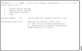
Step 4 Type 3 in the Select Option field and press Enter. The NEWS : Category Selection panel (Figure 3-2) is displayed.
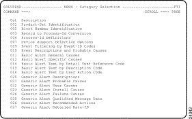
Step 5 Select 001 Product-Set Identification and press Enter. The NEWS : Product-Set Identification panel (Figure 3-3) is displayed.
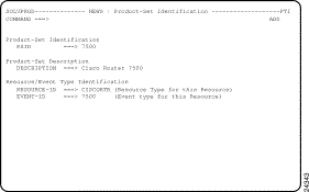
Step 6 To enable alerts from Cisco routers to be recognized, type information in the following fields and press Enter:
Step 7 Repeat Steps 5 and 6 for each series of Cisco routers that you are monitoring using ISM.
Step 8 To enable alerts from ISM to be recognized, type information in the following fields and press Enter:
Step 9 Press F3 to return to the NEWS : Category Selection panel.
Step 10 Select the 003 Record to Process-Id Conversion option to define the initial process identifier for the records you added. The NEWS : Record to Process-Id Conversion panel (Figure 3-4) is displayed.
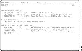
Step 11 To enable alerts from Cisco routers to be recognized, type information in the following fields and press Enter:
When you press Enter to save these details, a confirmation message is displayed.
Step 12 To enable alerts from ISM to be recognized, type information in the following fields and press Enter:
When you press Enter to save these details, a confirmation message is displayed.
Step 13 Press F3 to return to the NEWS : Category Selection panel.
Step 14 Select the 004 Process-Id Definitions option to define the name of the NCL procedure used to process the records you have added. The NEWS : Process-Id Definitions panel (Figure 3-5) is displayed.
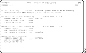
Step 15 Type information in the following fields and press Enter:
Step 16 Press F3 repeatedly to exit back to the SOLVE : Primary Menu.
Step 17 From the SOLVE : Primary Menu, type O in the Select Option field and press Enter. OCS is displayed.
Step 18 In OCS, enter CNM STOP to stop the SOLVE:Netmaster CNM interface.
Step 19 In OCS, enter CNM START to start the SOLVE:Netmaster CNM interface.
CISINTSL is an NCL procedure which can be used to update the NSCNTL file records to enable processing of router alerts, and to place ISM on the NEWS Device Support Menu. It can also be used to verify the updates that have been made via CISINSTL, or manual entry.
You run CISINSTL from the command line in OCS. It supports two parameters:
The most important of these is the Action parameter. It controls whether CISINTSL will add the control records to the NSCNTL file, or verify that the records exist and contain the correct parameters.
Begin by executing CISINSTL from the OCS command line, without any parameters.
If you have not used CISINSTL to add the records, and have not added the records manually, you should see a display similar to Figure 3-6.
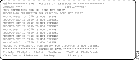
To use CISINSTL to add the NSCNTL file records, type the following command at the OCS command line and press Enter:
CISINSTL ACTION=ADD
The ISM: RESULTS OF VERIFICATION panel is displayed, as shown in Figure 3-7 to verify that the definition has been successfully created.
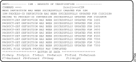
To verify that the automatic or manual updates have been completed successfully, issue the CISINSTL command again without using any parameters:
CISINSTL
The resulting verification panel should look like Figure 3-8.
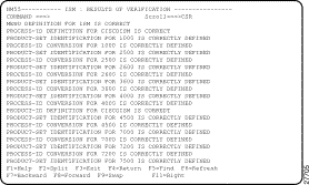
If there are any errors or omissions in the NSCNTL file definitions, warning messages are displayed to identify the discrepancies. Use the methods described in the "Enabling NMVT Forwarding and Processing" section to correct the problem.
ISM is accessed through the NEWS : Device Support Menu. Before you can use ISM, you need to add it to this menu in your SOLVE region.
To add ISM to your NEWS : Device Support Menu, complete the following steps:
Step 1 On the NEWS : Category Selection panel (Figure 3-2), select 007 Device Support Selection Options to define your menu entry for ISM on the NEWS : Device Support Menu. The NEWS : Device Support Selection Options panel (Figure 3-9) is displayed.
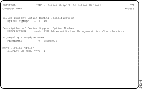
Step 2 Enter values in the following fields and press Enter:
Step 3 Press F3 repeatedly to return to the SOLVE : Primary Menu.
This section describes the updates required in VTAM to support ISM, which include:
The ISM program needs to receive the following VTAM messages over the PPO interface or via INMC-ISR:
Verify that you are not filtering these messages from reaching ISM.
If you are not currently using your own ISTEXCCS exit routine, install the ISM version, as described in the "Installing the VTAM XID Exit Routine" section.
If you have your own ISTEXCCS exit routine, or have installed the CiscoWorks Blue SNA View exit, call the Cisco Customer Technical Assistance Center (TAC) for instructions on modifying your existing routine to work with ISM Release 3.0.
The BEGIN vector is modified to indicate to VTAM that the exit should be called when VTAM receives an XID for defined PUs. When VTAM receives an XID for a defined PU the exit is invoked. The exit is passed information about the PU, including the PU name, local and remote MAC and SAP addresses for the PU session, the IDBLK/IDNUM for the PU, and finally RIF data if present. The exit information is passed to SOLVE:Netmaster using SOLVE Endpoint Services (EPS), each time that a switched PU connects into the network. The exit then returns a BUILD vector indicating that VTAM should allow the connection.
At VTAM termination, or when the exit is deactivated using the F NET,EXIT,ID=ISTEXCCS,OPT=INACT command, the exit is driven with the END vector. At this point the exit frees the allocated memory.
This process should produce minimal impact to VTAM connection performance.
Step 1 To install the ISM VTAM XID exit routine that was distributed with your ISM installation files, copy the member named NSPSOLVE from the hlq.CI300.CILOAD data set, to SYS1.VTAMLIB.
Step 2 To verify that the VTAM XID exit is installed properly, run the following VTAM command:
F NET,EXIT,ID=ISTEXCCS,OPT=ACT,MODULE=NSPSOLVE
Step 3 After you have verified that the VTAM XID exit has executed properly, rename the NSPSOLVE member to ISTEXCCS in SYS1.VTAMLIB.
Step 1 Review the comments in the NSPECSSL source member in hlq.CI300.CISAMP. Modify the member accordingly. Do not submit this member; it is used as input to the following step.
Step 2 Review the comments in the NSPASM source member in hlq.CI300.CISAMP. You should amend linkage editor INCLUDE statements to match the changes you made to NSPECSSL as directed by the comments in NSPASM. Then submit this job.
After you have updated your SOLVE initialization procedures, you need to restart SOLVE:Netmaster.
The following sections describe the next steps that you should perform to install ISM according to your site's current configuration.
If you are an existing NSP Release 2.0 site and you have completed the installation and verification procedures in this chapter, then you are ready to convert your NSP Release 2.0 files. To proceed with the NSP Release 2.0 migration task, see the "Migrating from NSP Release 2.0" chapter.
If this is the first time that ISM has been installed at your site and you have completed the installation and verification procedures in this chapter, then you are ready to configure the ISM program to manage your routers. To proceed with configuration of ISM, see the "Configuring ISM" chapter.
![]()
![]()
![]()
![]()
![]()
![]()
![]()
![]()
Posted: Tue Aug 24 08:53:33 PDT 1999
Copyright 1989-1999©Cisco Systems Inc.