|
|

This chapter provides detailed instructions on setting up the link between the mainframe host and a router, which is stage one of the ISM installation process. In this chapter you will find the following information:
To ensure successful configuration of the mainframe-to-router link, the network engineer should coordinate setup of the router configuration with the MVS systems programmer responsible for configuring the router's VTAM connection on the mainframe.
This section describes installation information that is relevant for the network engineer.
This section describes installation information that is relevant to the MVS systems programmer.
Before you can use ISM to view and manage a Cisco router from your SOLVE:Netmaster console, the router must be connected to the VTAM host through a systems services control point-to-physical unit (SSCP-to-PU) session. This connection is established by defining a PU for each router in the VTAM configuration file.
SWDRTRS VBUILD TYPE=SWNET | x | ||
SERVICE_POINT_NAME | PU | ADDR=01, | x |
Table 2-1 defines each of the VTAM arguments. For information about how these arguments correspond to the router configuration, see the "Correlating the Router and VTAM Configuration Information" section.
For detailed information about configuring and connecting Cisco routers, see the "Related Documentation" section.
To specify the name of your router, use the following command in global configuration mode:
hostname nameFor more information about using this command, see the Cisco IOS Configuration Fundamentals Configuration Guide.
To specify the privilege level and password for enable mode on the router, use the following command:
enable password [level level]{password | encryption-type encrypted-password}For more information about using this command, see the Cisco IOS Security Command Reference.
To configure SNA service point support on the router, you need to add Cisco IOS software sna host commands to the configuration file of your router. The specific commands that you add depend upon the type of connection that you wish to establish. For detailed information on configuring SNA service point support and the Cisco IOS software command for your interface type, see the Cisco IOS Bridging and IBM Networking Configuration Guide and Command Reference publications.
The following procedure shows the basic steps to define SNA service point support for Ethernet and Token Ring connections. Again, the actual commands that you use will depend upon the type of connection that you wish to establish. If you want to view some specific configuration examples, see the "Router Configuration Samples" section.
Step 1 Define a link to an SNA host in global configuration mode using the sna host command.
The following example shows the syntax of the sna host command for Token Ring, Ethernet, FDDI, RSRB, or virtual data-link control (VDLC) connections:
sna host host-name xid-snd xid rmac remote-mac rsap remote-sap lsap local-sap focalpoint
sna enable-host lsap lsap-address
Step 3 Start an outgoing connection when you are in interface configuration mode, using the command syntax:
sna start host-name
For more information about these commands and their options, see the Cisco IOS Bridging and IBM Networking Command Reference.
The following is an example of the lines that would appear in the configuration file of a router with an interface configured through a local ring to 3745 Token Ring Interface Connector:
!
sna host CWBC02 xid-snd 05dcc002 rmac 4001.3745.1088 rsap 4 lsap 4 focalpoint !
interface TokenRing0/1
	ip address 172.18.9.129 255.255.255.240
	ring-speed 16
	sna enable-host lsap 4
	sna start CWBC02
!
The following example shows the lines that would appear in the configuration file of a router that contains a Cisco mainframe channel connection with an interface configured for RSRB:
!
dspu rsrb 325 1 900 4000.7000.0001
dspu rsrb enable-host lsap 4
!
dspu host CWBC01 xid-snd 05dcc001 rmac 4000.3333.4444 rsap 4 lsap 4 focalpoint
!
dspu rsrb start CWBC01
!
interface Channel4/1
	no ip address
	no keepalive
	csna C010 C0
!
interface Channel4/2
	ip address 172.18.9.145 255.255.255.240
	no keepalive
	lan TokenRing 0
	source-bridge 28 1 900
	adapter 4 4000.3333.4444
The following example shows the lines that would appear in the configuration file of a router with an interface configured for DSPU with RSRB:
source-bridge ring-group 600
source-bridge remote-peer 600 tcp 172.18.9.19
!
dspu host CWBC09 xid-snd 05dcc009 rmac 4001.3745.1089 rsap 4 lsap 4 focalpoint dspu pool lupool host CWBC09 lu 2 16
!
dspu pu DSPUPC8 xid-rcv 05dcca18
dspu lu 2 9 pool lupool
!
interface TokenRing0
	ip address 172.18.9.19 255.255.255.240
	ring-speed 16
	multiring all
	source-bridge 85 3 600
	dspu enable-host lsap 4
	dspu start CWBC09
The following example shows the lines that would appear in the configuration file of a router with RSRB and an interface configured with loopback:
!
source-bridge ring-group 600
source-bridge remote-peer 600 tcp	172.18.10.97
source-bridge remote-peer 600 tcp	172.18.10.98
!
sna rsrb 1011 3 600 4000.ffff.00cb
sna rsrb enable-host lsap 4
!
sna host CWBC0B xid-snd 05dcc00b rmac 4001.3745.1089 rsap 4 lsap 4 focalpoint sna rsrb start CWBC0B
!
interface Loopback0
	ip address 172.18.10.97 255.255.255.252
!
The following is an example of the lines that would appear in the configuration file of a router that uses virtual data-link control over DLSw+:
source-bridge ring-group 99
dlsw local-peer peer-id 150.10.16.2
dlsw remote-peer 0 tcp 150.10.16.1
!
sna vdlc 99 4000.4500.01f0
sna vdlc enable-host lsap 12
!
sna host HOST-B xid-snd 065bbbb0 rmac 4000.7000.01f1 rsap 4 lsap 12 focalpoint
!
sna vdlc start HOST-B
!
interface serial 3
	description IP connection to dspu7k
	ip address 150.10.16.2 255.255.255.0
	clockrate 4000000
!
The following example shows the format of a Cisco IOS software sna host command that you use to configure the router for SNA Service Point support:
sna host host_name xid-snd xid rmac remote_mac [rsap rsap_addr] [lsap local_sap] [focalpoint]The values for the host_name and xid in the router configuration correspond to the VTAM PU definition in the following way:
SWDRTRS VBUILD TYPE=SWNET | x | ||
GLENDUSK | PU | ADDR=01, | x |
The sna host command in the router configuration for the router should appear:
sna host glendusk xid-snd 05dbb000 rmac 4001.3745.1088 rsap= 4001.3745.1088 fsap 4 lsap 4 focalpointFor more information about the sna host command, see the Cisco IOS Bridging and IBM Networking Command Reference.
If the verification procedures indicate a problem with the link, see the "Troubleshooting" chapter to diagnose the source of the error.
Step 1 From Operator Console Services (OCS), issue the following command for each router, where router_name is the hostname and service point name of the router that you are verifying:
D router_name
If properly configured and connected, the router status will display with an active (ACTIV) status. If the router does not display an active status, it is not successfully configured and attached to the network or the service point is not defined correctly in the configuration file of the router. See the "Troubleshooting" chapter to further diagnose the problem.
Step 2 Repeat Step 1 for each router that you plan to monitor using ISM.
The NEWS facility in SOLVE:Netmaster has a Service Point Support facility which supports communication between ISM and routers. To verify that a router can communicate with your SOLVE region, complete the following steps:
Step 1 On the SOLVE : Primary Menu, type N.S.8 in the Select Option field.
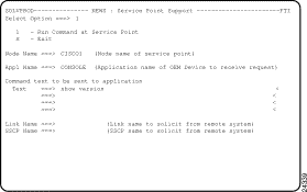
The NEWS : Service Point Support panel (Figure 2-1) is displayed.

Step 2 On the NEWS : Service Point Support panel, type 1 in the Select Option field.
Step 3 Type the node name of a router in the Node Name field.
Step 4 Type CONSOLE in the Appl Name field.
Step 5 Type show version in first line of the Text field and press Enter.
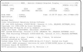
If the router is properly configured and connected, then the NEWS : Execute Command Response Display panel (Figure 2-2) is displayed, in response to the show version command.
If the router is not successfully configured and attached to the network or the service point is not defined correctly in the configuration file of the router, then an error message is displayed on the NEWS : Service Point Support panel. Press F1 to view help for the error message to further diagnose the problem.
Step 6 Repeat Steps 1 through 5 for each router that you plan to monitor using ISM.

Step 1 From the MVS console, issue the following command for each router name, where router_name is the hostname and service point name of the router that you are verifying:
D NET,ID=router_name,E
Step 2 Repeat Step 1 for each router that you plan to monitor using ISM.
See the "Troubleshooting" chapter for further information about the response to this command.
![]()
![]()
![]()
![]()
![]()
![]()
![]()
![]()
Posted: Tue Aug 24 08:30:12 PDT 1999
Copyright 1989-1999©Cisco Systems Inc.