|
|

Table Of Contents
Technical Notes for ISC Discovery
Using ISC Discovery with Cisco IP Solution Center MPLS VPN Management
Using ISC Discovery With Cisco IP Solution Center L2VPN Management
Using ISC Discovery with Cisco IP Solution Center MPLS Diagnostics Expert
Using ISC Discovery With Cisco IP Solution Center Traffic Engineering Management
Summary of Tasks for Discovery (Cisco ISC MPLS VPN Management and L2VPN Management)
Summary of ISC Discovery Steps for MPLS Diagnostics Expert
Step 1: Perform Preliminary Steps
(CDP Discovery Only) Verify That a Unique TIBCO Port Is Defined
(CDP Discovery Only) Verify That CDP Is Running on Devices To Be Discovered
Code XML Files Required for Discovery
Step 2: Perform Device Discovery
Setting General Device Attributes
Saving the Device Configuration
Step 3: Perform Discovery Data Collection
Step 4: Perform Role Assignment
Initiating Device Role Assignment
Changing the Device Assignment Display
Assigning Devices Individually or in Bulk
Saving the Role Assignment Information
Preliminary Steps Before Completing NPC Discovery for Metro Ethernet Networks
Step 6: Perform MPLS VPN Service Discovery (Optional)
Saving the MPLS VPNs and Initiating MPLS VPN Service Creation
Step 7: Perform L2VPN (Metro Ethernet) Service Discovery (Optional)
Viewing Discovered Layer 2 Services Grouped by VPN
Editing Discovered Layer 2 Services Grouped by VPN
Deleting Discovered Layer 2 Services Grouped by VPN
Viewing Discovered Layer 2 End to End Wires
Editing the VPN Associated with an End to End Wire
Splitting Layer 2 Service End to End Wires
Joining Layer 2 Service End to End Wires
Deleting Layer 2 Service End to End Wires
Viewing Discovered Layer 2 VPLS Links
Editing Discovered Layer 2 VPLS Links
Deleting Discovered Layer 2 VPLS Links
Saving the L2VPN Metro Ethernet Policy and Initiating Service Creation
Step 8: Commit Discovered Devices and Services to ISC Repository
Step 9: Create and Run a Collect Config Task for the Discovered Devices
Step 10: View and Edit Services
Service Inventory—Discovery
This chapter describes how to use the Discovery feature to discover devices, connections, and services for the IP Solution Center (ISC) provisioning process. It contains the following sections:
•
Technical Notes for ISC Discovery
•
•
•
•
•
•
•
•
•
•
•
•
Overview of ISC Discovery
ISC can expedite the process for building a network device inventory by discovering the devices, connections, and services that your MPLS VPN or L2VPN Metro Ethernet network comprises.
Note
Users who run service discovery should have a thorough understanding of their overall network topology, should be familiar with network terminology, such as: PE, N-PE, U-PE, PE-AGG, and CE, and should understand the definition of NPC and Metro Ethernet/MPLS services in ISC.ISC supports the discovery process for admin users only.
The ISC Discovery feature can be used to provision three of the applications in the Cisco ISC application suite:
•
•
•
Note
When a device in ISC only has a hostname, the ISC device has no IP management address or domain name configured. If in Discovery, a device with the same hostname is discovered with an IP management address or is created manually in the Device Editor, the device might fail to commit to the ISC repository. The failure occurs because a match is determined with the existing ISC device, because both devices do not have a configured domain name.
The workaround is to do either 1. or 2., as follows:
1.
or2.
The Cisco IP Solution Center Traffic Engineering Management has its own Discovery interface and process. This is documented in Chapter 2 of the Cisco IP Solution Center Traffic Engineering Management User Guide, 5.0, "TE Network Discovery."
Multiple service discovery processes are supported and you can restart from any of the previous steps. Support for multiple discovery processes allows you to do incremental discovery of the network. The ability to restart from previous steps helps you roll back the discovery process to a selected previous step. You can then resume discovery from that step instead of needing to restart the entire discovery process from the beginning. Restarting from discovery data collection prompts the user to select devices for which data needs to be collected.
Incremental discovery occurs for existing VPN links. The existing VPNs are not editable in the discovery GUI and the existing VPN links are by-passed during commit.
There is no synchronization in MPLS and L2VPN service discovery. Any modification must be done manually through the ISC user interface. Only new VPNs are discovered. Also, services on existing modified NPCs and conflicting NPCs are not discovered.
The commit to ISC happens only at the end of the discovery phase, not after each step. The Discovery process does not change the state of ISC during discovery workflow. It is only at the end of the workflow that a user can commit the discovered devices and services to ISC.
The Discovery process provides you with several choices on how to discover your network topology.
3.
a.
You can use the Cisco Discovery Protocol (CDP) to discover devices connected to an initial device that has an IP address you provide in a policy.xml file.
b.
You can use a Device/Topology-based method. This method uses XML files that specify device and NPC topology information.
c.
You can use an Import Configuration Files-based method. This method uses a directory on the server that contains configuration files for the devices to be discovered and an XML file that contains device connectivity information that is used to automatically create NPCs.
4.
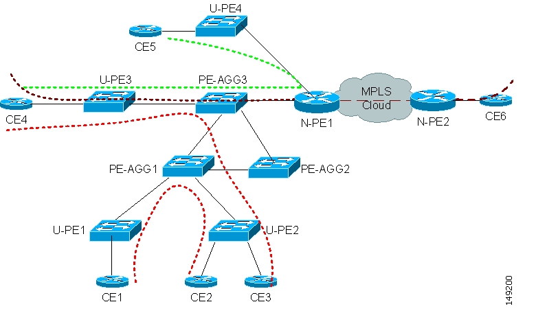
If you choose L2VPN (Metro Ethernet) Discovery, you can discover either a Metro Ethernet with an MPLS core, a Metro Ethernet with an Ethernet core, or a combination of the two, a mixed core. In a mixed core, the L2VPN services can span across the MPLS core or they can be confined to a local Ethernet domain alone (local switched services). Local switched services that do not traverse N-PE devices across an ethernet domain can also be discovered. Figure 4-1, " Mixed Core," shows a mixed core.Figure 4-1 Mixed Core
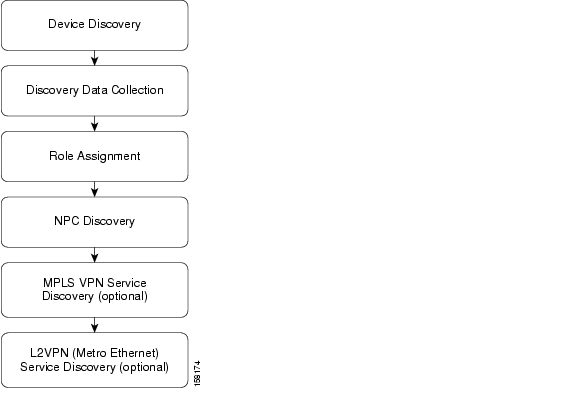
Figure 4-2 illustrates the phases in the Discovery process.
Figure 4-2 ISC Discovery Steps
Table 4-1 describes the phases in the Discovery process.
Technical Notes for ISC Discovery
This section presents technical tips and general information about the ISC Discovery process.
The ISC Discovery feature can be used to provision three of the applications in the Cisco ISC application suite:
•
•
•
Although the general steps are similar, there are some differences in the workflow for the various types of Discovery. These are described in the section covering each ISC application:
•
•
•
•
Note
This is documented in Chapter 2 of the Cisco IP Solution Center Traffic Engineering Management User Guide, 5.0, "TE Network Discovery."
For technical notes on using ISC Discovery in installations that include both Cisco IP Solution Center Traffic Engineering Management and Cisco IP Solution Center MPLS VPN Management, see Using ISC Discovery With Cisco IP Solution Center Traffic Engineering Management.
General Notes
Note the following points before running ISC Discovery:
•
•
•
•
•
•
•
Using the Discovery Log Files
A log file is written for each phase of the Discovery process. You can view a log file by clicking the View selection in the Log column next to each discovery phase summary on the Discovery Workflow window.
The log file provides useful information in the event a discovery step fails.
Using ISC Discovery with Cisco IP Solution Center MPLS VPN Management
If you are running the Discovery process to discover an MPLS VPN network for use with Cisco IP Solution Center MPLS VPN Management, note the following points:
•
•
•
•
Note
Using ISC Discovery With Cisco IP Solution Center L2VPN Management
If you are running the Discovery process to discover an L2VPN network that will be provisioned and managed using Cisco IP Solution Center L2VPN Management, note the following points:
•
•
•
–
–
–
•
•
•
•
Note
Using ISC Discovery with Cisco IP Solution Center MPLS Diagnostics Expert
If you are running the Discovery process to discover an MPLS VPN network for use with Cisco MPLS Diagnostics Expert, note the following points.
•
•
See Figure 4-5 for a flowchart of the required steps for ISC Discovery with Cisco IP Solution Center MPLS Diagnostics Expert.
•
Note
•
Using ISC Discovery With Cisco IP Solution Center Traffic Engineering Management
Normally you do not have to run the ISC Discovery process if you are using Cisco IP Solution Center Traffic Engineering Management. Cisco IP Solution Center Traffic Engineering Management has its own discovery process,. This process is documented in Chapter 2 of the Cisco IP Solution Center Traffic Engineering Management User Guide, 5.0, "TE Network Discovery."
However, if you are running both Cisco IP Solution Center Traffic Engineering Management (TEM) and Cisco IP solution Center MPLS VPN Management, you must run the Discovery process for Cisco IP Solution Center MPLS VPN Management.
Note the following points:
•
•
Summary of Tasks for Discovery (Cisco ISC MPLS VPN Management and L2VPN Management)
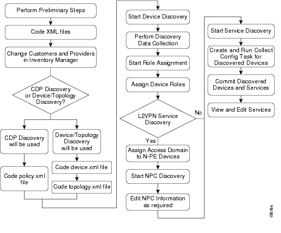
Figure 4-3 provides a general workflow diagram for the Discovery process used with the Cisco IP Solution Center MPLS VPN Management or Cisco IP Solution Center L2VPN Management application.
Note
Figure 4-3 Basic Workflow for Discovery with Cisco ISC MPLS VPN Management or Cisco ISC L2VPN Management
Table 4-2 describes each task in the Discovery workflow for Cisco ISC MPLS VPN Management and Cisco ISC L2VPN Management.
Table 4-2 Description of Discovery Steps for MPLS VPN and L2VPN Management
Step 1 : Perform Preliminary Steps
Perform preliminary steps that are required for ISC Discovery. See Step 1: Perform Preliminary Steps.
•
See Review System Requirements.
•
See Install Licenses.
•
See (CDP Discovery Only) Verify That a Unique TIBCO Port Is Defined
•
See (CDP Discovery Only) Verify That CDP Is Running on Devices To Be Discovered.
•
Step 2 : Perform Device Discovery
•
See Starting Device Discovery.
•
For information on entering device passwords, see Setting Password Attributes (Required Step).
•
See Setting General Device Attributes and Setting Cisco CNS Attributes.
Step 3 : Perform Discovery Data Collection
Start configuration collection. No input is required for this step. See Step 3: Perform Discovery Data Collection.
Step 4 : Perform Role Assignment
Assign device roles to each device. See Step 4: Perform Role Assignment.
Step 5 : Perform NPC Discovery
If you are discovering a Metro Ethernet Network with an Ethernet Core, perform the required preliminary steps. See Preliminary Steps Before Completing NPC Discovery for Metro Ethernet Networks
•
See Step 5: Perform NPC Discovery.
•
See Adding a Device for an NPC, Adding a Ring, Inserting a Device, Inserting a Ring, or Deleting a Device or a Ring.
Step 6 : Perform MPLS VPN Service Discovery (optional)
Start MPLS VPN Service Discovery. See Step 6: Perform MPLS VPN Service Discovery (Optional).
This step is required for the Cisco IP Solution Center MPLS VPN Management application,
Note
Step 7 : Perform L2VPN Service Discovery (optional)
Start L2VPN Service Discovery. See Step 7: Perform L2VPN (Metro Ethernet) Service Discovery (Optional).
This step is required for the Cisco IP Solution Center L2VPN Management application.
Note
Step 8 : Commit Discovered Devices and Services to ISC Repository
Commit the discovered devices and services to the ISC repository. Prior to this step, discovery workflow stores the discovered devices and services in a temporary repository, which gets committed to ISC only at the last step of discovery workflow.
Step 9 : Create and Run a Collect Config Task for Discovered Devices
From the ISC Start Page, choose Monitoring > Task Manager. Select the Collect Config task and select all of the devices discovered in the Device Discovery step; then submit the task.
See Step 9: Create and Run a Collect Config Task for the Discovered Devices.
Step 10 : View and Edit Services
The discovered services will be in Pending state and you need to do a config audit to move them to Deployed state. See Step 10: View and Edit Services.
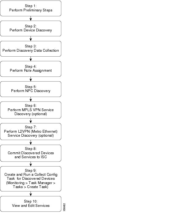
Within each step, additional tasks must be performed and choices must be made. Figure 4-4 shows a detailed flowchart that illustrates all of the steps in the Discovery workflow.
Figure 4-4 Detailed Diagram of Discovery Steps (Cisco ISC MPLS VPN Management and Cisco ISC L2VPN Management)
Summary of ISC Discovery Steps for MPLS Diagnostics Expert
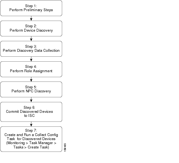
Figure 4-5 shows the basic Discovery steps for Cisco ISC with the MPLS Diagnostics Expert (MDE) application. For MDE, several of the steps required for Cisco ISC MPLS VPN Management and Cisco ISC L2VPN Management are not required.
Figure 4-5 Discovery Workflow for the MPLS Diagnostics Expert Application
Table 4-3 Description of Discovery Steps for MPLS Diagnostics Expert
Step 1 : Perform Preliminary Steps
Perform preliminary steps that are required for ISC Discovery.
•
See Review System Requirements.
•
See Install Licenses
•
For specific instructions, see the following section:
Step 2 : Perform Device Discovery
•
See Starting Device Discovery.
•
For information on entering device passwords, see Setting Password Attributes (Required Step).
•
See Setting General Device Attributes and Setting Cisco CNS Attributes.
Step 3 : Perform Discovery Data Collection
Start configuration collection. No input is required for this step. See Step 3: Perform Discovery Data Collection.
Step 4 : Perform Role Assignment
Assign device roles to each device. See Step 4: Perform Role Assignment.
For MDE, you normally discover only P and PEs and assign P and PE roles to them However, if you discover CEs, assign CE roles to the CE devices.
Note
Step 5 : Create and Run a Collect Config Task for Discovered Devices
From the ISC Start Page, choose Monitoring > Task Manager. Select the Collect Config task and select all of the devices discovered in the Device Discovery step; then submit the task.
See Step 8: Commit Discovered Devices and Services to ISC Repository.
Step 1: Perform Preliminary Steps
Before you initiate the ISC Discovery process, complete the following preliminary steps:
•
•
•
•
•
•
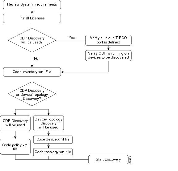
Figure 4-6 summarizes the preliminary steps for ISC Discovery.
Figure 4-6 Summary of Preliminary Steps for Discovery
Review System Requirements
Cisco recommends that you thoroughly review the system requirements for ISC before planning your installation, to be sure that you have all the hardware and software that you must successfully install.
The system recommendations and requirements for ISC are listed in Chapter 1, "System Recommendations" of the Cisco IP Solution Center Installation Guide, 5.0 and in the Release Notes for Cisco IP Solution Center, 5.0.1.
Install Licenses
Before starting Discovery, the appropriate licenses (both Activation and VPN licenses) must be installed. Also, each license must be large enough to handle all possible discovered objects. For information on installing licenses, see the "Installing License Keys" section of Chapter 2 of the Cisco IP Solution Center Installation Guide, 5.0, "Installing and Logging In to ISC."
Discovery in Large Networks
To discover large networks with a complex topology, we recommend you reset two DCPL properties, as follows:
Step 1
Step 2
Step 3
Step 4
Heap is a block of memory segment for the L2VPN and Metro Ethernet, Layer 3 MPLS VPN, and TEM components. It is allocated for use by the Java virtual machine (JVM) process during runtime. It might need to be increased for large deployments. If the httpd process restarts, increase the heap size, as follows:
Step 1
Step 2
Step 3
Step 4
Step 5
Step 6
Step 7
(CDP Discovery Only) Verify That a Unique TIBCO Port Is Defined
If you are using CDP Discovery to discover the network topology, make sure the TIBCO Port is unique. Otherwise, CDP discovery will fail.
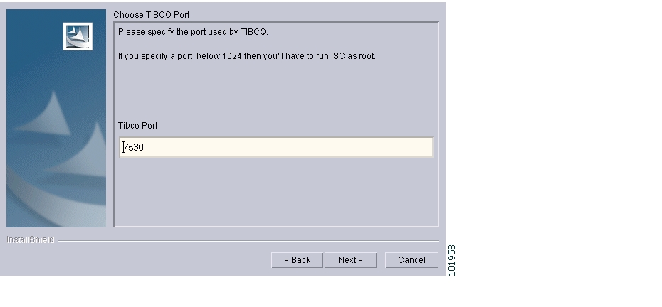
During installation, the TIBCO port can be specified if the "custom" Installation Type is selected at the start of the installation process. Otherwise, the default port installed is 7530. You specify the TIBCO port on the Choose TIBCO Port dialog.
The port number that is specified must be unique throughout the network, and no other ISC installations are allowed with the same port.
Figure 4-7 shows the Choose TIBCO Port dialog.
Figure 4-7 Choose TIBCO Port
The Tibco port can be changed after installation by modifying vpnsc.properties.
(CDP Discovery Only) Verify That CDP Is Running on Devices To Be Discovered
If CDP Discovery is going to be used, use the show cdp command to ensure that CDP is running on all of the devices intended to be discovered.
For each device, enter the show cdp command, as shown in Example 4-1.
Example 4-1 The show cdp Command:
Router# show cdpGlobal CDP information:Sending CDP packets every 120 secondsSending a holdtime value of 180 secondsSending CDPv2 advertisements is enabledRouter#
Note
Code XML Files Required for Discovery
Before you can run ISC Discovery, you must code XML files that are required for the Discovery process. A different set of files is required, depending on whether you use CDP Discovery or Device/Topology-based Discovery.
Table 4-4 describes the XML files and indicates which files are required for each type of discovery method.
Note
Sample XML Files
The initial installation of ISC provides sample XML files that you can use as a starting point in coding your own XML files. The sample XML files are located in the following directory:
<install_directory>/resources/discovery/sample
where install_directory is the installation directory that you specified when prompted by the ISC installation program.
Coding the policy.xml File
The policy.xml file:
•
•
•
•
•
Example 4-2 shows the sample policy.xml file that is provided with the ISC installation.
Example 4-2 Sample policy.xml File
<?xml version='1.0' encoding='UTF-8'?><DISCOVERY_POLICY overwrite_existing_policy="true"><DISCOVERY_METHOD><CDP ipaddress="209.168.133.232" hop="1"/></DISCOVERY_METHOD><SNMP_COMMUNITY><RO_COMMUNITY><COMMUNITY community="public"/></RO_COMMUNITY><RW_COMMUNITY><COMMUNITY community="private"/></RW_COMMUNITY></SNMP_COMMUNITY></DISCOVERY_POLICY>If there are additional routers that are on the other side of PE routers on the edge of the core segment of the network, you can specify more than one seed IP address in order to discover these devices.
Example 4-3 shows a policy.xml file that contains two seed IP addresses.
Example 4-3 Policy.xml File with Two IP Addresses
<?xml version='1.0' encoding='UTF-8'?><DISCOVERY_POLICY overwrite_existing_policy="true"><DISCOVERY_METHOD><CDP ipaddress="209.168.133.241" hop="8"/></DISCOVERY_METHOD><DISCOVERY_METHOD><CDP ipaddress="209.168.133.244" hop="8"/></DISCOVERY_METHOD><SNMP_COMMUNITY><RO_COMMUNITY><COMMUNITY community="public"/></RO_COMMUNITY><RW_COMMUNITY><COMMUNITY community="private"/></RW_COMMUNITY></SNMP_COMMUNITY></DISCOVERY_POLICY>Table 4-5 describes the XML tags used in the policy.xml file.
Follow these steps to edit the sample policy.xml file:
Step 1
This IP address is a device that can be reached from the ISC host. For each seed device, an accessible interface on the starting point is configured, because the management interface must be provided. The management interface is the address on the device that the ISC host uses to reach the device.
Note
Step 2
When you choose the seed devices and hop count, pick a seed device that can reach a large section of the network. Pick one or more of them until you think these devices will enable you to reach your entire managed network.
Point-of-presence (POP) routers are usually good choices. If you choose all the POPs in your network as the collection of seed devices and put in the appropriate number of hubs, you discover the entire managed network.
To pick the hop count number, go to the CE that is the furthest from its associated POP, and count the number of devices between them. If this number is N, the hub number is N+1, assuming you are picking the POP as the seed.
Step 3
Within the additional <DISCOVERY_METHOD> tags, include <CDP> tags.
For each <CDP> tag, specify an IP address with the ipaddress attribute and a hop count with the hops attributes.
Step 4
When you run the Discovery process, the process queries the starting point device for its CDP table. From this table, all of those devices are queried for their CDP information. This process continues until the maximum hop count from the starting point is reached. When you use the CDP-based method, note that only devices running CDP are discovered.
Coding the device.xml File
The device.xml file:
•
•
•
•
•
Example 4-4 shows a sample device.xml file. Use the sample file as an example and save your edited file in an appropriate directory.
Example 4-4 Sample device.xml file
<network><device><device-name>mlpe8</device-name><ip-address>209.168.133.244</ip-address><system-object-id>.1.3.6.1.4.1.9.1.509</system-object-id><snmp-info><ro-community>public</ro-community></snmp-info></device><device><device-name>mlsw11</device-name><ip-address>209.168.133.170</ip-address><system-object-id>.1.3.6.1.4.1.9.1.574</system-object-id><snmp-info><ro-community>public</ro-community></snmp-info></device><device><device-name>mlsw16</device-name><ip-address>209.168.133.175</ip-address><system-object-id>.1.3.6.1.4.1.9.1.574</system-object-id><snmp-info><ro-community>public</ro-community></snmp-info></device><device><device-name>mlsw17</device-name><ip-address>209.168.133.176</ip-address><system-object-id>.1.3.6.1.4.1.9.1.574</system-object-id><snmp-info><ro-community>public</ro-community></snmp-info></device></network>Table 4-6 describes the XML tags used in the device.xml file.
Follow these steps to code the device.xml file:
Step 1
Step 2
•
•
•
•
Step 3
Coding the topology.xml File
The topology.xml file:
•
•
•
•
•
The topology.xml file specifies the discovery protocol that is used in the discovery process, and, for each connection, specifies the starting IP address, the starting interface, the end device, and the end interface
Example 4-5 shows a sample topology.xml file. Use the sample file as an example and save your edited file in an appropriate directory.
Example 4-5 Sample topology.xml File
<topology><connection discovery-protocol="CDP" fromDevice="mlsw19" fromIP="209.168.133.178" fromInterface="GigabitEthernet1/1/2" toDevice="mlsw21" toIP="209.168.133.220" toIF="GigabitEthernet1/1/1" ></connection><connection discovery-protocol="CDP" fromDevice="mlsw19" fromIP="209.168.133.178" fromInterface="FastEthernet1/0/23" toDevice="mlsw21" toIP="209.168.133.220" toIF="FastEthernet1/0/24" ></connection><connection discovery-protocol="CDP" fromDevice="mlsw19" fromIP="209.168.133.178" fromInterface="FastEthernet1/0/24" toDevice="mlsw18" toIP="209.168.133.177" toIF="FastEthernet1/0/23" > </connection><connection discovery-protocol="CDP" fromDevice="mlsw19" fromIP="209.168.133.178" fromInterface="FastEthernet1/0/22" toDevice="mlsw22" toIP="209.168.133.221" toIF="FastEthernet1/0/24" ></connection></topology>Table 4-7 describes the XML tags used in the topology.xml file.
Follow these steps to code the topology.xml file:
Step 1
Step 2
•
•
•
•
•
•
•
Step 3
Step 2: Perform Device Discovery
This section describes how to start the device discovery process and edit device configuration.
Starting Device Discovery
To start discovery, follow these steps:
Step 1
Step 2
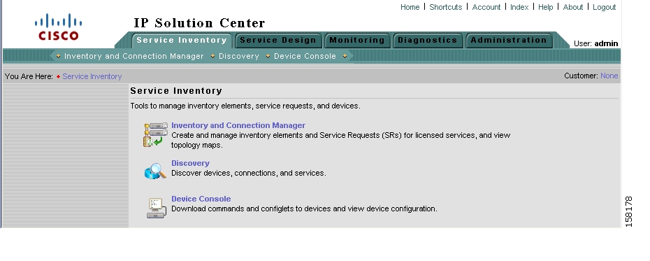
Step 3
Figure 4-8 Service Inventory Window
Step 4
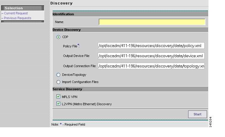
The Discovery window appears, as shown in Figure 4-9.
Initially, the CDP Discovery method is selected and the window displays the required input for this method.
Figure 4-9 Device Discovery—CDP Fields
The editable Output Device File field is optional and defaults to an XML file of the discovered devices. This file can then be an input Devices File for rerunning discovery using the Device/Topology option, by choosing that radio button.
The editable Output Connection File is optional and defaults to an XML file that contains device connectivity information that is written during CDP Device Discovery. This file can then be an input NPC Topology File for rerunning discovery using the Device/Topology option, by choosing that radio button.
Step 5
•
•
•
Figure 4-10 Device Discovery—Device/Topology Fields
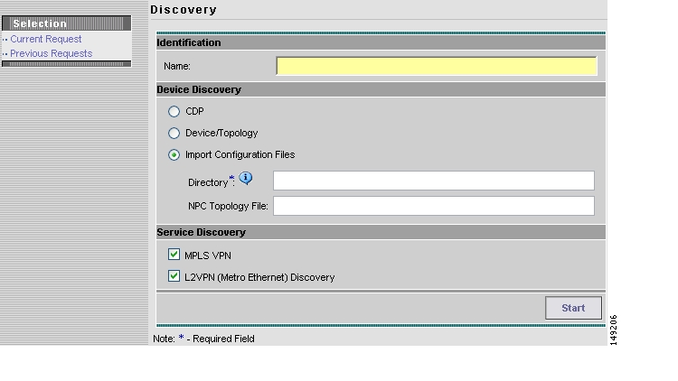
Figure 4-11 Device Discovery—Import Configuration File Fields
The required Directory field is the directory on the server that contains configuration files for the devices to be discovered. The format of these files must be <filename>.cfg.
The NPC Topology File field contains an XML file that contains device connectivity information that is used to automatically create NPCs.
Note
Step 6
Table 4-8 Discovery Settings
Name
In this field, enter a unique name of your choice for the Workflow name. If you do not enter a name in this field, the system automatically generates a unique name for you.
CDP
Click this radio button to select Cisco Discovery Protocol (CDP) as the Discovery method.
Policy File
If you click the CDP button, specify the path to your policy.xml file here. This file is an XML file that indicates the IP address of one or more devices used as a starting point for the discovery process.
For more information on the policy.xml file, see Coding the policy.xml File.
Output Device File
This editable optional field defaults to an XML file of the discovered devices. This file can then be an input Devices File for rerunning discovery using the Device/Topology option.
Output Connection File
This editable optional field defaults to an XML file that contains device connectivity information that is written during CDP device discovery. This file can then be an input NPC Topology File for rerunning discovery using the Device/Topology option.
Device/Topology
Click this radio button to select Device/Topology as the Discovery method.
Devices File
If you click the Device/Topology button, specify the path to your device.xml file here. This file contains information used to locate the devices in your network, such as IP addresses and OIDs.
For more information on the device.xml file, see Coding the device.xml File.
NPC Topology File
If you click this optional Device/Topology button, specify the path to your topology.xml file here. This file contains information used to determine the NPC topology of your network.
For more information on the topology.xml file, see Coding the topology.xml File.
Import Configuration Files
Click this radio button to select Import Configuration Files as the Discovery method.
Directory
This required field is the directory on the server that contains configuration files for the devices to be discovered. The format of these files must be <filename>.cfg.
NPC Topology File
This field contains an XML file that contains device connectivity information that is used to automatically create NPCs.
MPLS VPN
To discover devices used in an MPLS VPN service, click the MPLS VPN radio button.
L2VPN (Metro Ethernet) Discovery
To discover layer 2 devices used in a Metro Ethernet service, click the L2VPN (Metro Ethernet) Discovery radio button.
Step 7
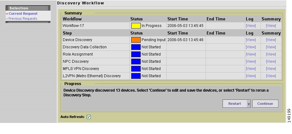
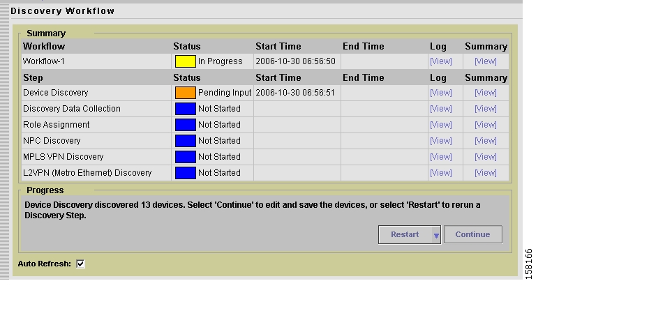
The discovery process starts and the Discovery Workflow window appears, as shown in Figure 4-12.
Figure 4-12 Discovery Workflow Window
The Workflow category in the data pane gives the name information about the current discovery request/workflow.
Click the Restart button and you receive a drop-down list of completed steps. Select a step and you will restart from that step.
In the left column, Current Request gives the discovery request/workflow that is currently running. If there is no currently running discovery request/workflow, an initialization window appears to create a new discovery request/workflow.
In the left column, Previous Requests lists all the discovered requests/workflows. You can look at the status and logs for any of these discovery requests/workflows.
Discovery Workflow window indicates the progress of each phase of device discovery:
•
•
•
Figure 4-13 Discovery Workflow Window with Device Input Pending
The Progress area at the bottom of the window indicates how many devices were discovered.
At the lower right of the window there is a Restart button. You can click this button to restart the entire discovery process. However, if you restart the Discovery process, any work that has been done previous to restarting Discovery is lost.
Note
Editing Device Configurations
After the initial discovery of devices in your network, you must edit the information that ISC maintains about the devices. This allows the Discovery process to collect configuration information about the devices that are required to determine the network topology and generate service requests.
Editing device configuration includes these steps:
•
•
•
Follow these steps to edit device configurations:
Step 1
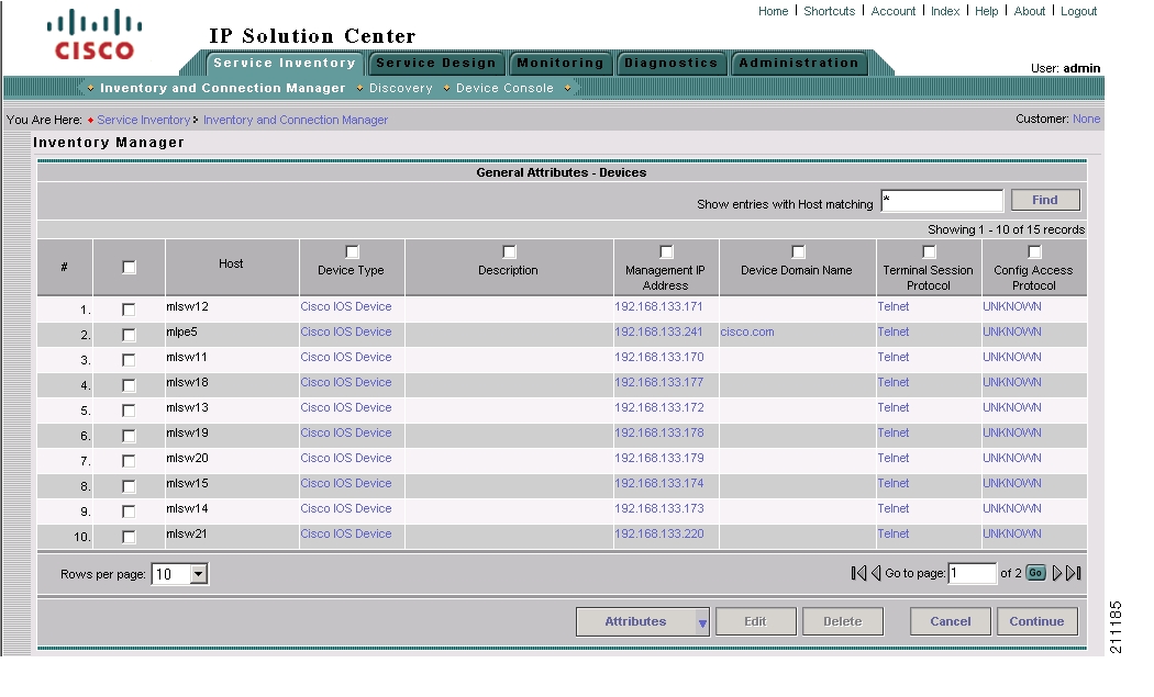
Step 2
Figure 4-14 The General Attributes-Devices Window
The General Attributes - Devices window allows you to do the following:
1.
If devices appear in the device list that you do not want to configure, you can delete them, as explained in Step 5.
2.
–
You can accept the default attributes shown in the General Attributes - Devices window or change them as required.
For a list of the general attributes, see Setting General Device Attributes.
–
–
Step 3
If the Find field displays an asterisk, all devices are displayed.
The setting in the Find field applies to all of the attributes windows.
Step 4
•
If the General Attributes - Devices window is not the current window, click the Attributes button and select General Attributes from the pull-down list.
See Setting Password Attributes (Required Step) for instructions on setting the General Attributes.
•
For instructions on setting the password attributes, see Setting Password Attributes (Required Step).
Note
•
Step 5
a.
If you need to delete more than one device, you can check the check box next to the heading for the list of the devices. This selects all of the devices in the list. You can then uncheck the boxes next to any devices that you do not want to delete.
b.
Setting Password Attributes (Required Step)
In order for the Configuration Collection phase to succeed, you must set the password attributes for each device. Follow these steps to set password attributes:
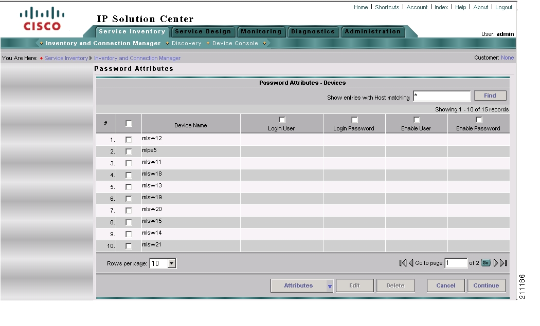
Step 1
Step 2
Figure 4-15 Password Attributes Window
Step 3
a.
If several devices have the same password attributes, you can check multiple check boxes. If all of the devices have the same password attributes, you can check the box to the left of the heading row to select all of the devices in the list. If this check box is checked, you can uncheck it to deselect all of the devices.
b.
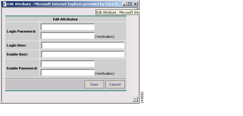
Step 4
The Edit Attributes window for passwords appears, as shown in Figure 4-16.
Figure 4-16 Edit Attributes Window for Password Attributes
Step 5
•
•
•
•
Step 6
The information that you entered appears in the Password Attributes window.
Setting General Device Attributes
After you complete the device discovery process, the General Attributes - Devices window displays the current general attributes settings for each device.
Follow these steps to change the general attributes for a device:
Step 1
An Edit Attributes dialog box appears for the selected attribute.
Step 2
The General Device attributes include the following:
•
•
•
•
•
•
Setting Cisco CNS Attributes
If one of the devices is a Cisco CNS device, follow these steps to set CNS attributes:
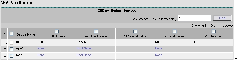
Step 1
Step 2
Figure 4-17 CNS Attributes Window
The Terminal Server column specifies the devices that represent the workstations that can be used to provision edge routers, and the Port Number column specifies the port numbers used by the terminal server.
Step 3
The Edit Attributes dialog box for Event Identification appears.
Step 4
Saving the Device Configuration
After you are finished making device configuration changes, click the Continue button.
The Device Discovery indicator turns green and indicates that Device Discovery is Complete.
The Discovery Data Collection phase begins automatically.
Step 3: Perform Discovery Data Collection
After you save your device configuration settings, the Discovery Data Collection phase of Device Discovery starts automatically.
While Cisco IP Solution Center is collecting the device configurations, the Discovery Data Collection indicator is yellow and indicates that the process is In Progress.
When the Discovery Data Collection phase is complete, the indicator changes to green and indicates that the process is Complete. You are now ready to assign device roles.
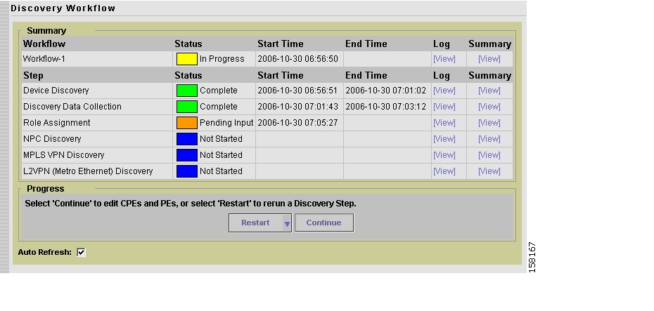
Step 4: Perform Role Assignment
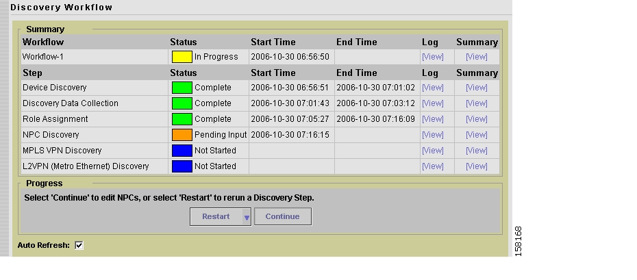
After the Discovery Data Collection phase of Device Discovery is complete, the Discovery Workflow window indicates that the Role Assignment phase is Pending Input, as shown in Figure 4-18.
Figure 4-18 Discovery Workflow with Role Collection Pending Input
Restarting from Discovery Data Collection prompts you to select the devices for which discovery data collection needs to occur.
Follow these steps to assign device roles:
•
•
•
•
•
•
The following sections describe each of these steps.
Initiating Device Role Assignment
Follow these steps to initiate device role assignment:
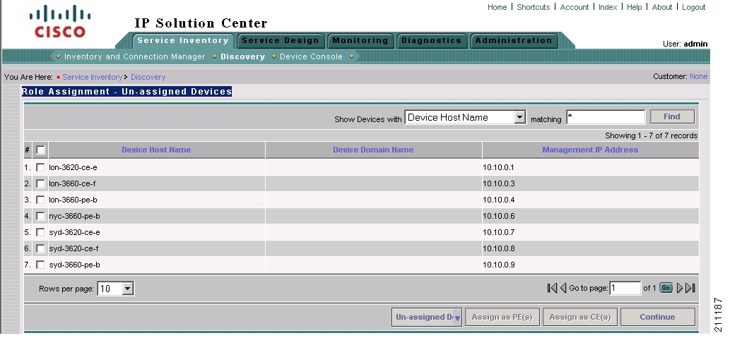
Step 1
The Role Assignment - Un-assigned Devices window appears, as shown in Figure 4-19.
Figure 4-19 Role Assignment - Un-assigned Devices Window
On the Role Assignment - Un-assigned Devices window, if you select a single device, you are prompted directly for the device role assignment. However, if you select more than one device, either the Role Assignment - CEs window or the Role Assignment - PEs window appears. On these windows you can specify the desired device roles.
Step 2
Changing the Device Assignment Display
You can change the way devices are displayed in the Role Assignment window in the following ways:
•
•
Follow these steps to change the category of devices that is displayed:
Step 1
•
•
•
Step 2
•
•
•
The value in the matching field specifies a search mask that controls which devices are displayed. An asterisk (*) specifies display of all devices by the selected search criteria. A string followed by an asterisk specifies display of all devices starting with part of a hostname, domain name, or management IP address. And a string preceded by an asterisk specifies display of all devices ending with part of a hostname, domain name, or management IP address.
You can specify more than one wildcard (asterisk) value in a search string. For example, to display all devices that have "ce" in the hostname, enter *ce* in the matching field.
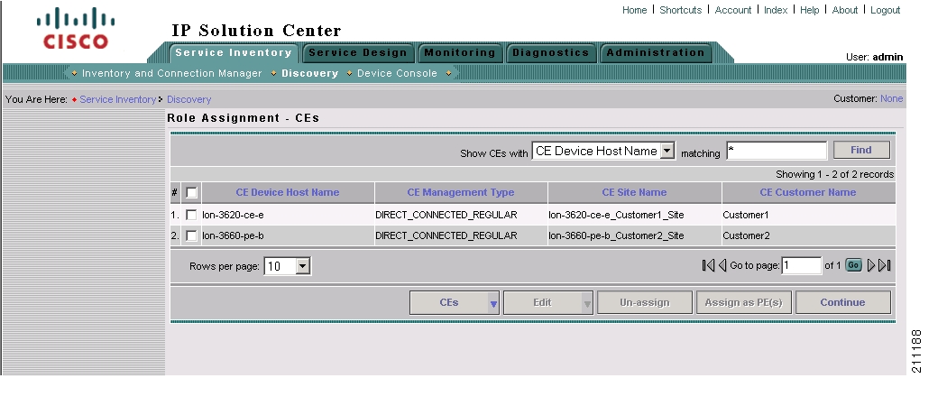
The display changes depending on the selection that you made. For example, if two devices have been assigned the CE role, the Role Assignment - CEs window appears and shows a listing similar to the one in Figure 4-20.
Figure 4-20 Role Assignment - CEs Window
Changing Device Assignments
In some instances, the device discovery process assigns the wrong device role to groups of devices. For example, devices that should be PEs can be assigned as CEs.
If this occurs, perform these steps:
•
–
–
The Role Assignment - PEs window appears and now lists the devices that you assigned as PEs.
•
Assigning Devices Individually or in Bulk
Using the windows provided for Role Assignment, you can assign device roles one device at a time or using bulk assignment (by selecting several devices and assigning them all the same role).
If you assign device roles for a single device, you can also assign the other device attributes, such as Site, Region, etc. However, if you assign device roles in bulk, then you cannot assign the other attributes at this time. You will have to go to the PEs or CEs window later to assign the other attributes.
Determine Device Roles
The purpose of device assignment is to categorize the devices discovered in the provider's network into two general groups:
•
See Assigning the PE Role for instructions on assigning the PE roles (U-PE, N-PE, P, or PE-AGG).
•
See Assigning the CE Role for instructions on assigning the CE role.
For PE devices, use the following guidelines to determine device roles:
•
•
•
•
For CE devices, see the descriptions of the CE roles in the section on assigning CE roles ( Assigning the CE Role) for specific information.
Assigning the PE Role
Follow these steps to assign a device as a PE device:
Step 1
•
•
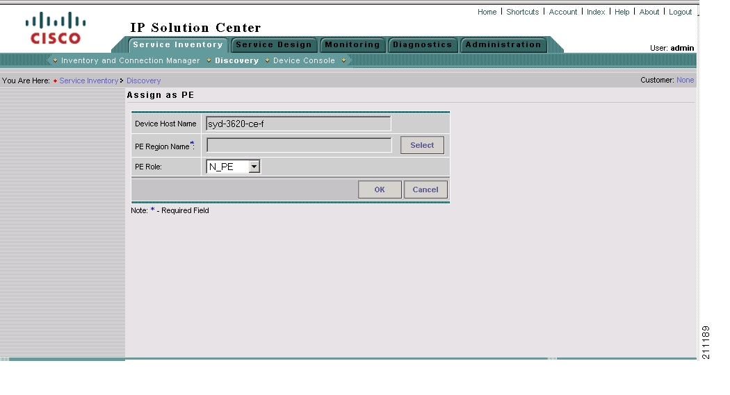
Step 2
The Assign as PE window appears, as shown in Figure 4-21.
Figure 4-21 Assign as PE Window
Step 3
a.
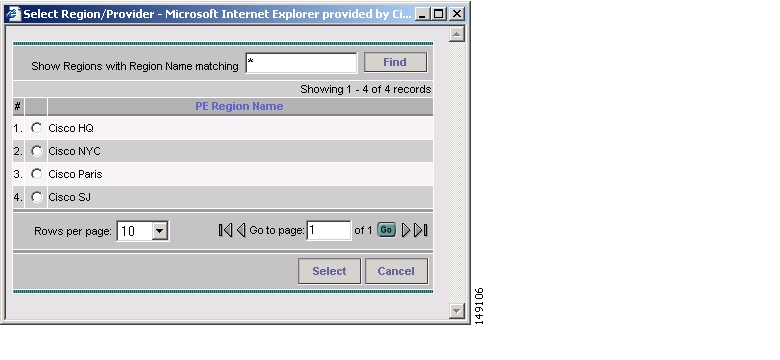
The PE Region Name window appears, as shown in Figure 4-22.
Figure 4-22 PE Region Name Window
b.
The Assign as PE window appears with the region name in the PE Region field.
c.
The PE role specifies the architectural role that a PE router performs. Assign the PE role based on the network layer to which the device belongs.
You can select the following PE roles:
–
–
–
–
d.
The Role Assignment - PEs window appears with the specified values shown.
Editing the PE Role
After you have assigned one or more devices as PE devices and they appear in the Role Assignment - PEs window, you can edit the PE role. You can edit the PE role even if no values have been assigned in the Assign as PE window.
Note
Follow these steps to edit the Role Assignment values for a PE device:
Step 1
If the Role Assignment - Un-assigned Devices or the Role Assignment - CEs window is active, select Role-Assignment - PEs from the pull-down list at the bottom of the window.
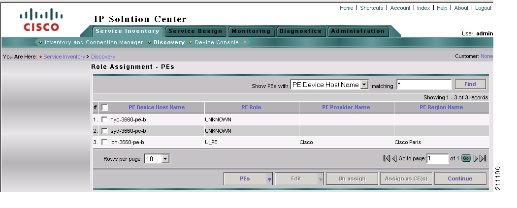
The Role Assignment - PEs window appears, as shown in Figure 4-23.
Figure 4-23 Role Assignment - PEs Window
Note that on this window, sorting is disabled for the following columns:
•
•
•
In the sample window shown in Figure 4-23, one of the PEs has role information assigned. The other two PEs have been assigned as PEs but do not have role information assigned. You can edit any of the information for the PEs, whether information has been entered or not.
Step 2
•
•
Step 3
a.
You are prompted to select a PE role.
b.
You can select the following PE roles:
–
–
–
–
The specified PE role appears in the Role Assignment - PEs window.
Step 4
a.
You are prompted for a Region name.
b.
The specified Region Name and its associated Provider Name appear in the Role Assignment - PEs window.
Assigning the CE Role
Follow these steps to assign a device as a CE device:
Step 1
•
•
Step 2
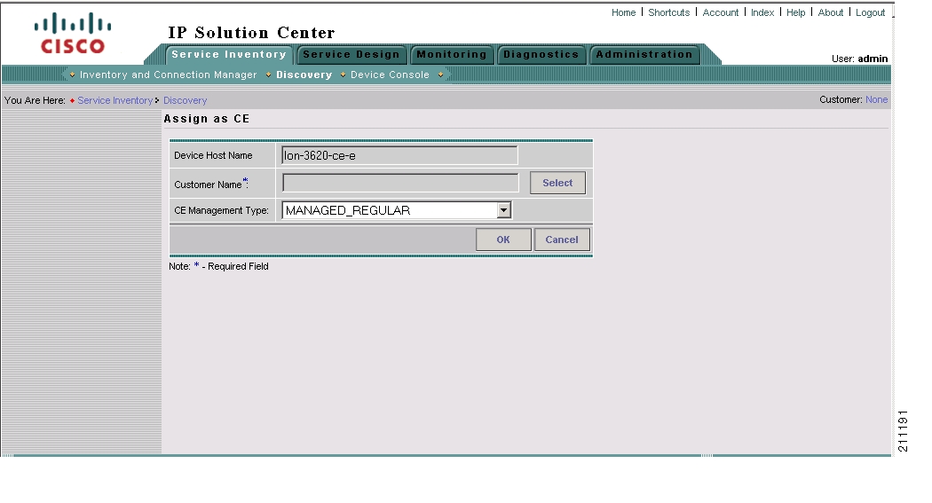
Step 3
Figure 4-24 Assign as CE Window
Step 4
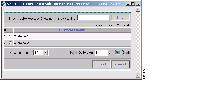
a.
The Customer Name window appears, as shown in Figure 4-25.
Figure 4-25 Customer Name Window
b.
The Assign as CE window appears with the specified customer name displayed.
c.
The CE Management type specifies the architectural role that a CE router performs. Assign the CE management type based on the network layer to which the device belongs.
You can select the following CE management types:
–
–
–
–
–
–
–
–
d.
The Role Assignment - CEs window appears with the specified values shown.
Note
Editing the CE Role
After you have assigned one or more devices as CE devices and they appear in the Role Assignment - CEs window, you can edit the CE role. You can edit the CE role even if no values have been assigned in the Assign as CE window.
Follow these steps to edit the Role Assignment values for a CE device:
Step 1
If the Role Assignment - Un-assigned Devices or the Role Assignment - PE window is active, select Role-Assignment - CEs from the pull-down list at the bottom of the window.
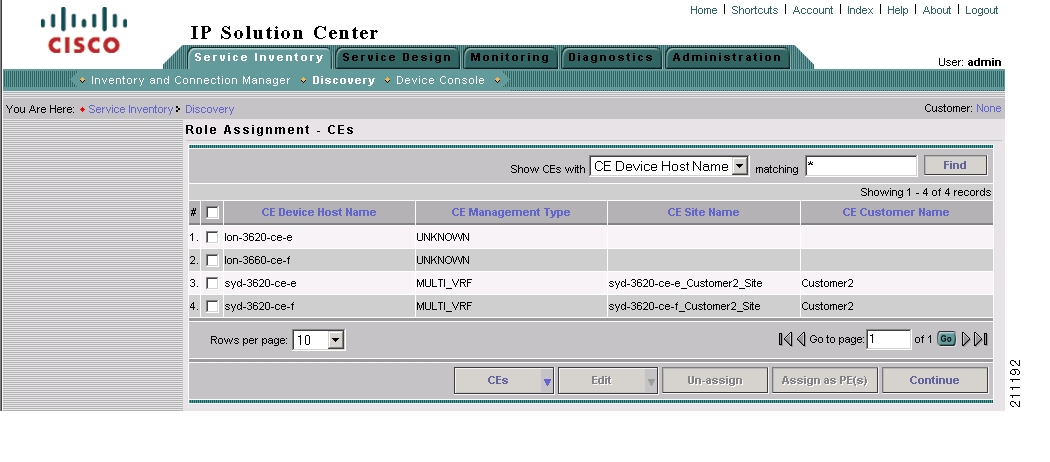
The Role Assignment - CEs window appears, as shown in Figure 4-26.
Figure 4-26 Role Assignment - CEs Window
In the sample Role Assignment - CEs window shown in Figure 4-26, two of the CEs have role assignment information assigned, and two have no information assigned. You can edit any of the information for the CEs, whether information has been entered or not.
Note that on this window, sorting is disabled on the following columns:
•
•
•
Step 2
•
•
Step 3
a.
You are prompted to select a customer name.
b.
The Role Assignment - CEs window appears with the specified customer name displayed.
Step 4
a.
b.
The CE Management type specifies the architectural role that a CE router performs. Assign the CE management type based on the network layer to which the device belongs.
You can select the following CE management types:
–
–
–
–
–
–
–
–
c.
The Role Assignment - CEs window appears with the specified CE management type displayed.
Step 5
a.
b.
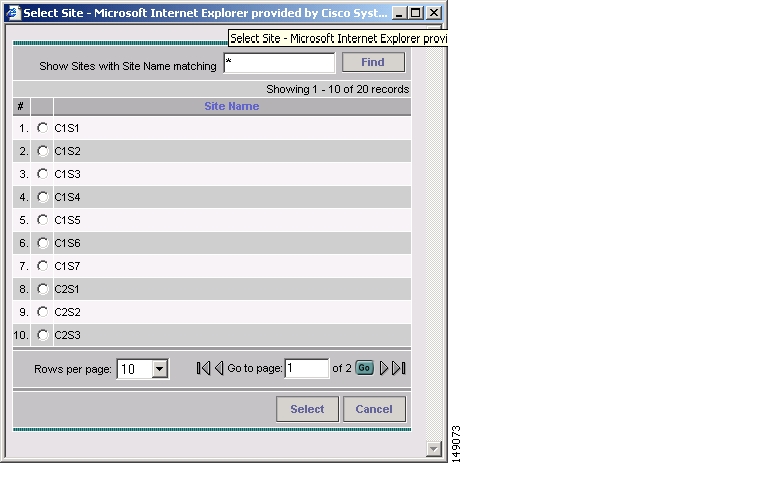
The Site Name window appears, as shown in Figure 4-27.
Figure 4-27 Site Name Window
c.
The Role Assignment - CEs window appears with the specified site names displayed.
Saving the Role Assignment Information
After you finish assigning roles to the devices, click the Continue button.
The Role Assignment Discovery indicator turns green and indicates that Role Assignment is Complete.
You are now ready to start the NPC Discovery phase of Device Discovery.
Step 5: Perform NPC Discovery
After the Role Assignment phase of Device Discovery is complete, the Discovery Workflow window indicates that the NPC Discovery phase is Pending Input, as shown in Figure 4-28.
Figure 4-28 Discovery Workflow with NPC Discovery Pending Input
Follow these general steps to view a list of the NPCs that have been discovered and add or remove NPCs as required:
•
•
•
Preliminary Steps Before Completing NPC Discovery for Metro Ethernet Networks
Follow these steps if you are discovering a Metro Ethernet topology with an Ethernet core.
•
•
•
These steps are performed using the Inventory and Connection Manager in the Service Inventory interface (Service Inventory > Inventory and Connection Manager).
Create Access Domains
Follow these steps to create access domains and add discovered devices to the domains:
Step 1
Step 2
The Inventory and Service manager window appears.
Step 3
The Access Domains window appears.
Step 4
For detailed instructions on creating Access Domains, see the "Creating Access Domains" section on page 3-125.
Create Resource Pools
Follow these steps to create a resource pool:
Step 1
Step 2
The Inventory and Service manager window appears.
Step 3
The Resource Pools window appears.
Step 4
Step 5
Step 6
Step 7
For detailed instructions on creating Resource Pools, see the "Resource Pools" section on page 3-126.
Edit Inter-N-PE Interfaces
Follow these steps to edit the "Inter N-PE" interfaces for the devices in your Metro Ethernet topology:
Note
Step 1
Step 2
The Inventory and Service manager window appears.
Step 3
The PE Devices window appears.
Step 4
a.
The Edit PE window appears.
b.
c.
d.
Go the following section, Starting NPC Assignment and follow the steps for starting NPC assignment.
Starting NPC Assignment
Follow these steps to initiate NPC assignment:
Step 1
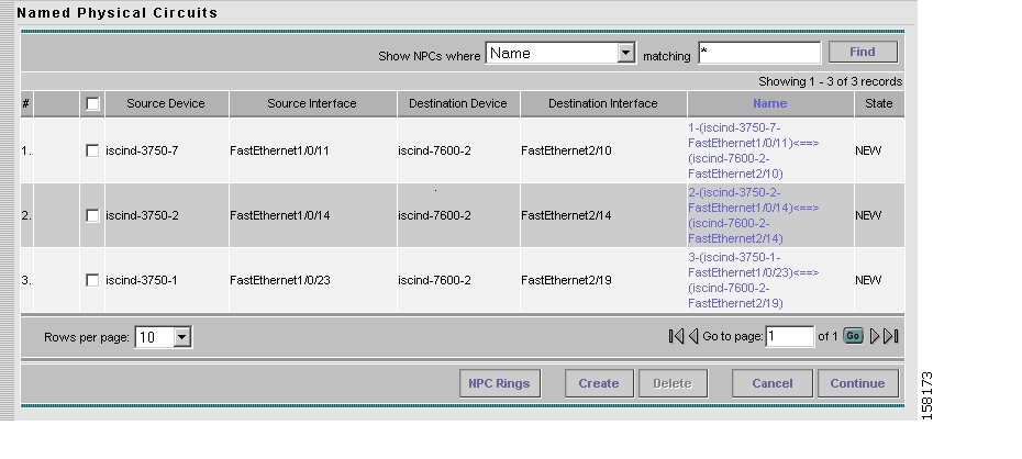
The Named Physical Circuits window appears, as shown in Figure 4-29.
Figure 4-29 Named Physical Circuits Window
The Named Physical Circuits window initially displays any discovered circuits.
At this point, you can create, add, or remove NPCs as required.
The State column has the following categories:
•
•
•
•
Named physical circuits (NPCs) are named circuits that describe a physical connection between a CPE or U-PE and a N-PE. The intermediate nodes of the NPCs can either be U-PE or PE-AGG. They can be connected in a circular fashion forming a ring of devices, which is represented by an entity known as NPC Rings. NPC Rings represent the circular topology between devices to the Named Physical Circuits. To create an NPC, you must specify how the source CPE/U-PE and the destination N-PE are connected and specify the intermediate nodes.
Step 2
a.
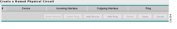
The Create a Physical Circuit window appears, as shown in Figure 4-30.
Figure 4-30 Create Physical Circuits Window.
Initially, the list of NPCs is empty.
b.
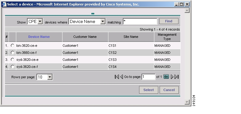
The Select a Device window appears, as shown in Figure 4-31.
Figure 4-31 Select a Device Window
Step 3
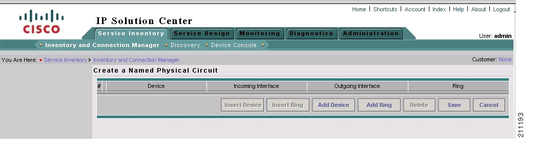
The Create a Named Physical Circuit window appears with an initial device added, as shown in Figure 4-32.
Figure 4-32 Create a Named Physical Circuit Window with Initial Device Added
The buttons on the window are now active.
c.
–
–
–
–
–
Step 4
Adding a Device for an NPC
Step 1
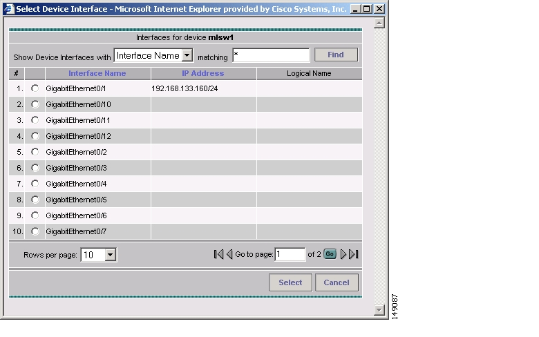
The Select Device Interface window appears, as shown in Figure 4-33.
Figure 4-33 Select Device Interface Window
This window shows the interfaces on the selected device.
Step 2
The selected interface now appears in the Create a Named Physical Circuit window.
Step 3
A list of interfaces configured on the device appears
Step 4
The outgoing interface now appears in the Create a Named Physical Circuit window.
Step 5
Step 6
Adding a Ring
Follow these steps to add a ring before the currently selected device:
Note
Step 1
The Select NPC Rings window appears. This window shows any rings that exist in the network topology.
Step 2
The selected ring now appears in the Create a Named Physical Circuit window.
Inserting a Device
To insert a device after the last device in the topology, follow these steps:
Step 1
The Select a Device window appears, as shown in Figure 4-31.
Step 2
The device now appears on the Create a Named Physical Circuit window.
Step 3
A list of interfaces on the selected device appears.
Step 4
The selected interface now appears on the list of interfaces.
Inserting a Ring
To insert a ring after the last device in the topology, follow these steps:
Step 1
A list of the currently existing rings appears.
Step 2
The selected ring now appears on the Create a Named Physical Circuit window.
Deleting a Device or a Ring
Follow these steps to delete a device or a ring:
Step 1
The create NPC window appears with the device deleted.
Saving the NPC Configuration
After you have selected two devices and have configured the connection between them, follow these steps to save the NPC configuration:
Step 1
The NPC process validates the NPC configuration.
Step 2
The workflow window appears with NPC discovery marked as completed, as shown in Figure 4-34.
Figure 4-34 NPC Complete Window
Step 6: Perform MPLS VPN Service Discovery (Optional)
After you have completed the NPC Discovery phase of Device discovery, if you selected MPLS VPN Discovery when you initiated the Discovery process, the NPC Discovery phase is marked as complete, and the MPLS VPN Discovery step is marked as Pending Input.
You are now ready to initiate configuration of the discovered MPLS VPN using the MPLS VPN Discovery user interface. Follow these steps to configure MPLS VPN services:
Note
Step 1
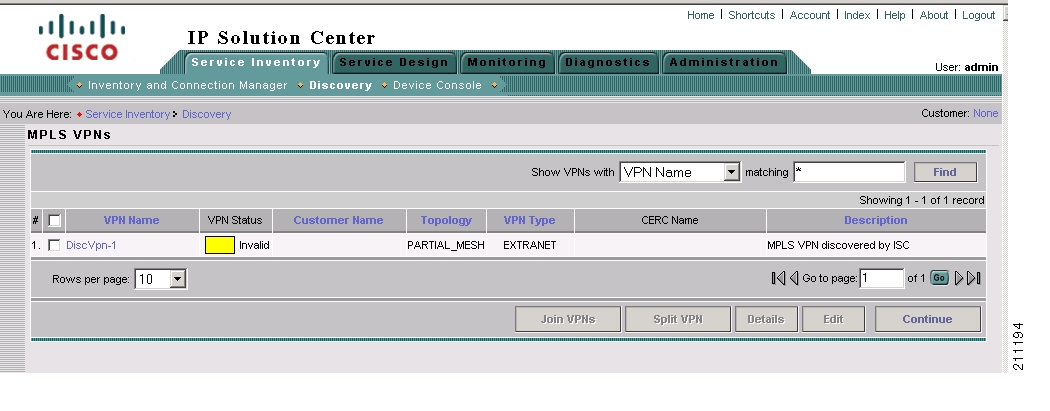
The MPLS VPNs window appears and lists the MPLS VPNs that were discovered. The status of the discovered MPLS VPNs is indicated as follows:
•
•
The MPLS VPN window shown in Figure 4-35 shows an invalid MPLS VPN (the topology is Partial Mesh and the Customer Name is blank).
Figure 4-35 MPLS VPNs Window with Invalid MPLS VPN
Note
Step 2
•
For a description of the MPLS VPN view options, see Filtering the MPLS VPN View.
•
•
–
See Splitting a VPN for instructions.
–
See Creating a VPN for instructions.
Filtering the MPLS VPN View
Follow these steps to change the view in the MPLS VPNs window:
Step 1
You can filter the list of VPNs by VPN Name, Customer Name, Topology, VPN Type, or Description.
Step 2
The value in the matching field specifies a search mask that controls which sites are displayed. An asterisk (*) specifies display of all sites by the selected search criteria. A string followed by an asterisk specifies display of all sites starting with part of the element specified in the Show VPNs with field.
You can specify more than one wildcard (asterisk) value in a search string. For example, to display all VPNs that have "cisco" as part of the Customer Name, enter *cisco* in the matching field.
The display changes to display the VPNs with the selected criteria.
Splitting a VPN
In some situations, you might need to split an existing MPLS VPN before you complete the MPLS VPN Discovery process and actually create the MPLS VPN services.
For example:
•
•
Follow these steps to split a VPN:
Step 1
Step 2
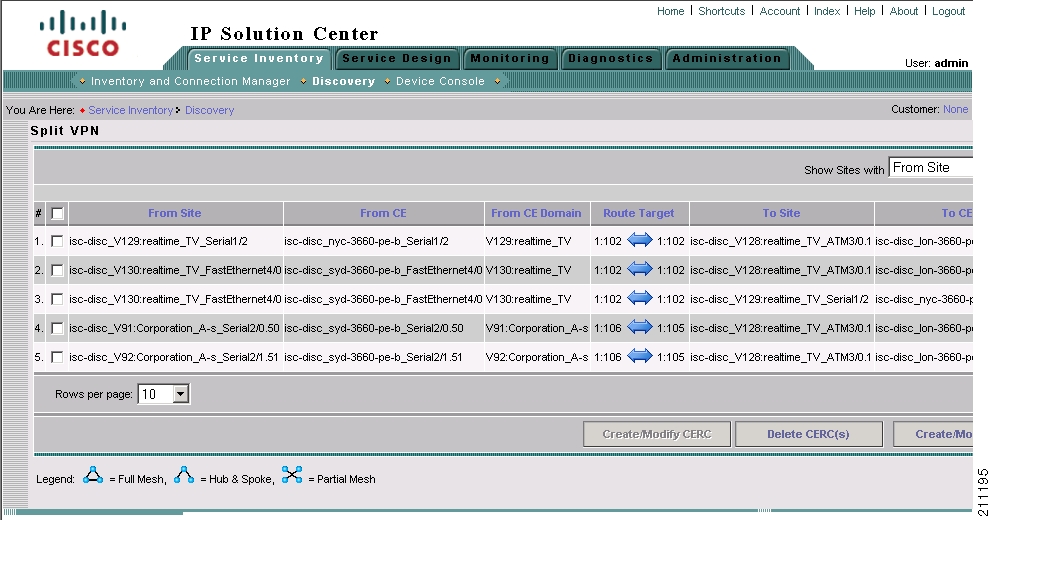
The Split VPN window appears, as shown in Figure 4-36 and Figure 4-37.
Figure 4-36 Split VPN Window (Left Portion)
Figure 4-37 Split VPN Window (Right Portion)
Step 3
In the example shown in Figure 4-37, select the links that would comprise either a Hub and Spoke or Full Mesh topology.
For example, in the Split VPN window shown in Figure 4-36 and Figure 4-37, the first three links all have Route Targets of 1:102 and together form a Full Mesh topology.
The remaining two links have Route Targets of 1:106 and 1:105. These links together form a Hub and Spoke topology.
To split this VPN, the first three links need to be associated with one CERC, and the two remaining links need to be associated with another CERC. Then we can split this VPN into two separate VPNs following the ISC best practice convention of one CERC per VPN.
Step 4
You are prompted for a CERC name.
Step 5
Step 6
For example, in the topology shown Figure 4-36 and Figure 4-37, select the devices that have the route target 1:106 to 1:105.
Step 7
Step 8
The Split VPNs window appears again, and the right portion of the window shows the new CERCs that have been created.
Figure 4-38 shows an example.
Figure 4-38 Split VPNs Window After Creation of a Valid CERC Topology
Notice that in the example in Figure 4-38, the two new CERCs that have been created (valid_cerc_one and valid_cerc_two), have valid topologies. The first CERC, valid_cerc_one, has a Full Mesh topology and the second CERC, valid_cerc_two, has a Hub and Spoke topology.
Step 9
You are now ready to continue to the next step, creating VPNs and adding CERCs to the VPNs.
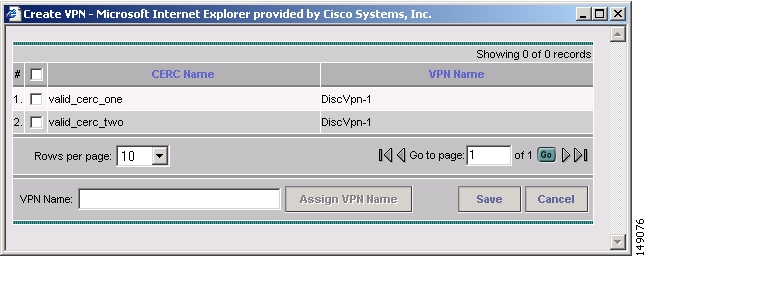
Creating a VPN
After you have created a CERC, you must create a VPN and then add the CERC to it.
Follow these steps to create a VPN:
Step 1
The Create VPN window appears, as shown in Figure 4-39.
Figure 4-39 Create VPN Window
Step 2
In the example shown in Figure 4-39, select valid_cerc_one.
Step 3
For this example, enter vpn_one.
Step 4
Step 5
The VPN is created and appears in the Split VPN window in the VPN Name field.
Step 6
Continuing with the CERCs shown in the sample windows in Splitting a VPN, a VPN must be created and have a CERC assigned to it. To do this:
a.
b.
In the example screen, you could select the second CERC (valid_cerc_two) to the newly created VPN to it.
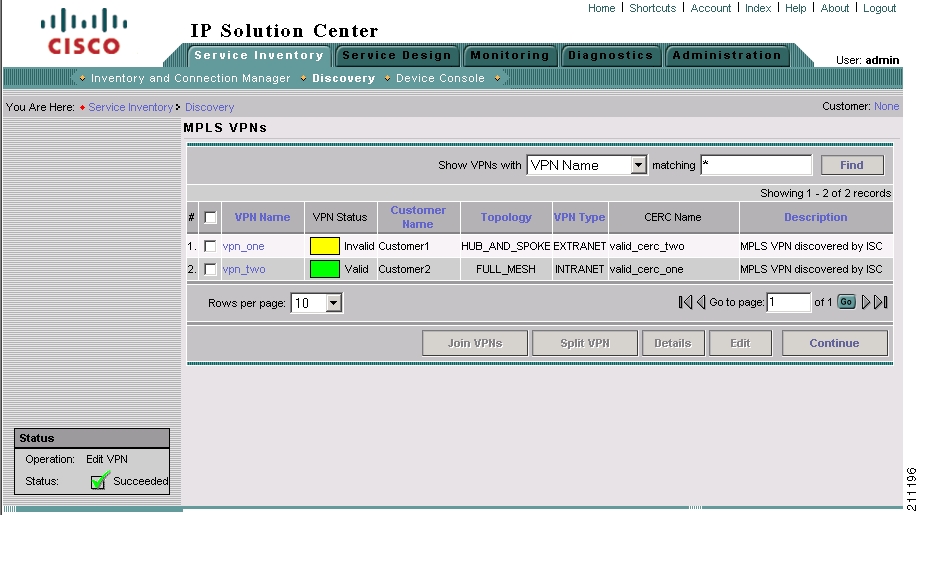
Step 7
The MPLS VPNs window appears, as shown in Figure 4-40.
Figure 4-40 MPLS VPNs Window with Valid VPN and Invalid VPN
Note
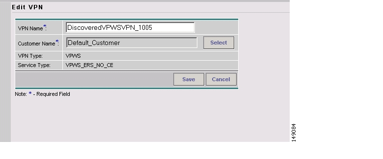
This occurs because in some instances, the MPLS Discovery process cannot completely validate the data. In this situation, you can still continue with the Service Discovery process and create MPLS VPN services. However, the process will skip the invalid VPN, and you must configure the VPN service manually using the ISC provisioning commands.Step 8
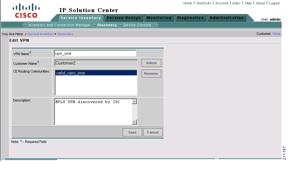
a.
The Edit VPN window appears, as shown in Figure 4-41.
Figure 4-41 Edit VPN Window
b.
A list of customer names appears.
c.
d.
e.
The Customer name now appears in the MPLS VPNs window.
Note
Step 9
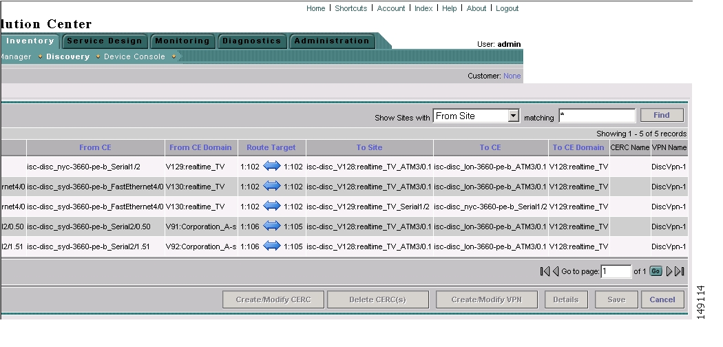
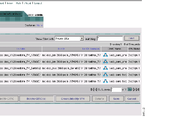
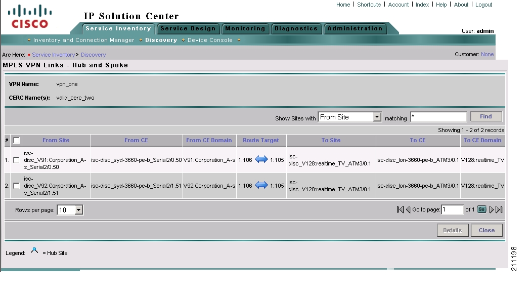
Viewing VPN Link Details
Follow these steps to view details of VPNs that were discovered:
Step 1
The MPLS VPN Link window appears, as shown in Figure 4-42.
Figure 4-42 MPLS VPN Links Window
Step 2
You can filter the list of VPNs by From Site, From CE, From CE Domain, Route Target, To Site, To CE, or to CE Domain.
The value in the matching field specifies a search mask that controls which sites are displayed. An asterisk (*) specifies display of all sites by the selected search criteria. A string followed by an asterisk specifies display of all sites starting with part of the element specified in the Show Sites with field.
You can specify more than one wildcard (asterisk) value in a search string. For example, to display all sites that have "realtime" in the From CE Name, select From CE Name in the Show Sites with field and then name, enter *realtime* in the matching field.
The display changes to show only the specified links.
Saving the MPLS VPNs and Initiating MPLS VPN Service Creation
After you are finished editing the data for the discovered MPLS VPNs in the MPLS VPNs window, click the Continue button.
The Discovery process creates VPN services. After the process is complete, the Discovery Workflow window indicates that the MPLS VPN Discovery process is COMPLETE and the status indicator is green.
If you also selected L2VPN (Metro Ethernet) Discovery in the Discovery window before starting the Discovery process, you can now proceed to Metro Ethernet service discovery.
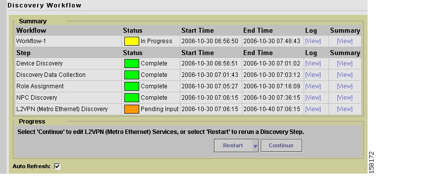
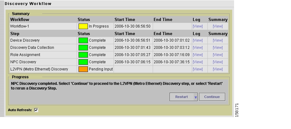
Step 7: Perform L2VPN (Metro Ethernet) Service Discovery (Optional)
If you selected L2VPN (Metro Ethernet) Discovery in the Discovery window before starting the Discovery process, then after the previous steps are complete, the Discovery Workflow window shows the L2VPN (Metro Ethernet) Discovery as Pending Input, as shown in Figure 4-43.
Figure 4-43 Discovery Workflow Window with MPLS Ethernet Discovery Pending Input
Follow these steps to initiate Metro Ethernet Service Discovery:
Note
Step 1
a.
b.
c.
For detailed instructions, see the "Creating Access Domains" section on page 3-125.
d.
e.
f.
For detailed instructions, see the "Resource Pools" section on page 3-126.
g.
The Discovery Workflow window shows the L2VPN (Metro Ethernet) Discovery process as Pending Input.
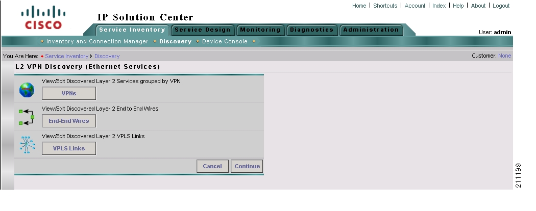
Step 2
The L2VPN Discovery (Ethernet Services) window appears, as shown in Figure 4-44.
Figure 4-44 L2VPN Discovery (Ethernet Services) Window
Step 3
•
•
•
The following sections of this chapter describe each of these actions.
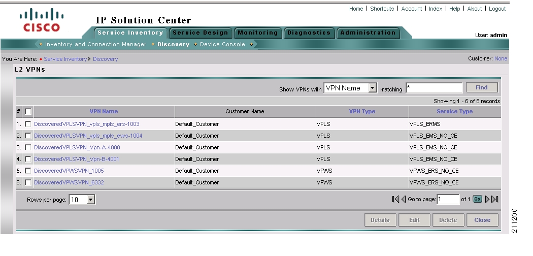
Viewing Discovered Layer 2 Services Grouped by VPN
Follow these steps to view discovered Layer 2 services grouped by VPN:
Step 1
The L2VPNs window appears, as shown in Figure 4-45.
Figure 4-45 L2VPNs Window
The L2VPNs window allows you to perform the following tasks:
•
This task is explained in the following steps of this procedure.
•
See Editing Discovered Layer 2 Services Grouped by VPN for detailed instructions.
•
See Deleting Discovered Layer 2 Services Grouped by VPN for instructions on this task.
Step 2
The Link Details window appears, as shown in Figure 4-46.
Figure 4-46 Link Details Window
The Link Details window shows the details about the discovered VPN, such as the User-Network Interface (UNI), in a table format.
Step 3
Editing Discovered Layer 2 Services Grouped by VPN
You can edit a discovered Layer 2 VPN service to change the policy that is applied to the service. Follow these steps to edit a Layer 2 VPN service:
Step 1
The Edit Link Policy window appears, as shown in Figure 4-47.
Figure 4-47 Edit Link Policy Window
Step 2
a.
A list of policies appears.
You can change the list of policies by choosing a filter from the pull-down list in the Show VPN policies with field and/or entering a search mask in the Matching field.
You can filter the policy list by Policy Name, Customer Name, Provider Name, or Global policy name. And you can limit the lists of policies displayed in the selected category by entering a value in the Matching field.
Step 3
Step 4
•
•
Deleting Discovered Layer 2 Services Grouped by VPN
Follow these steps to delete a Layer 2 service:
Step 1
The following message appears:
Links/End to End wires associated with all selected VPNs will be deleted as a result of
this operation. Do you really want to Delete?
Step 2
If you click OK, the VPN and associated links and end-to-end wires are deleted.
Viewing Discovered Layer 2 End to End Wires
Follow these steps to view discovered Layer 2 end-to-end wires:
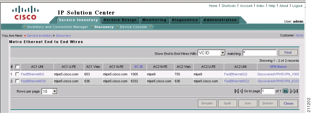
Step 1
The Metro Ethernet End to End Wires window appears, as shown in Figure 4-48.
Figure 4-48 Metro Ethernet End to End Wires Window
The Metro Ethernet End to End Wires window allows you to perform the following tasks:
•
This task is explained in the following steps of this procedure.
•
See Editing the VPN Associated with an End to End Wire for a description of this task.
•
See Splitting Layer 2 Service End to End Wires for a description of this task.
•
See Joining Layer 2 Service End to End Wires for a description of this task.
•
See Deleting Discovered Layer 2 Services Grouped by VPN for instructions on this task.
Step 2
The Link Details window appears, as shown in Figure 4-49.
Figure 4-49 Link Details Window
Step 3
Step 4
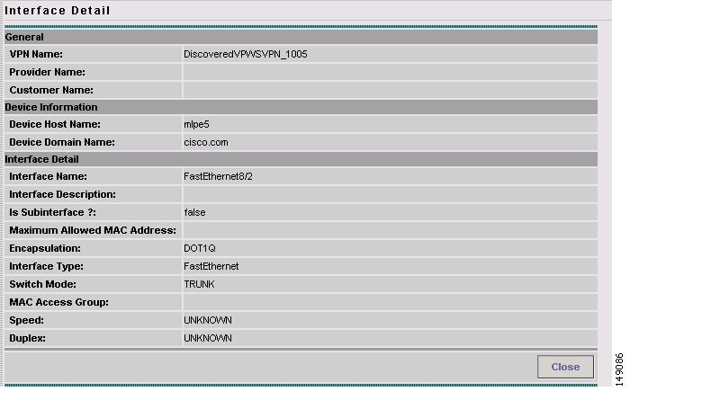
If you click on an interface name, the Interface Detail window appears, as shown in Figure 4-50.
Figure 4-50 Interface Detail Window
The Interface Detail window shows details about the selected interface, such as the hostname of the host where the interface is located, the type of encapsulation used on the interface, and the switch mode used on the interface.
Step 5
Editing the VPN Associated with an End to End Wire
From the Metro Ethernet End to End Wires window, you can also edit the VPN that is associated with the end-to-end wire.
Follow these steps to edit the VPN associated with an end-to-end wire:
Step 1
The Edit VPN window appears, as shown in Figure 4-51.
Figure 4-51 Edit VPN Window for L2VPN VPNs
Step 2
Step 3
a.
A list of customers appears.
b.
c.
The new VPN name and/or Customer Name appears in the Metro Ethernet End to End Wires window.
Splitting Layer 2 Service End to End Wires
You can split off an existing end-to-end wire from the VPN that it is associated with and associate it with a new VPN.
Follow these steps to split an end-to-end wire from an existing VPN:
Step 1
Note
Step 2
A message appears asking if you want to proceed.
Step 3
The end-to-end wires are split and are associated with two new VPNs. These names of the VPNs are created by the system by adding a new number to the end of the existing VPN name.
Joining Layer 2 Service End to End Wires
You can join two existing end-to-end wires to a single VPN.
Follow these steps to join two existing end-to-end wires:
Step 1
A message appears asking if you want to proceed.
Step 2
The selected end-to-end wires are joined to a new VPN. The name for this VPN is created by the system by adding a new number to the end of the existing highest numbered VPN name.
Deleting Layer 2 Service End to End Wires
Follow these steps to delete an existing end-to-end wire:
Step 1
A message appears asking if you want to proceed.
Step 2
The selected end-to-end wire (or wires) is deleted. Any Attachment Circuit(s) associated with the wire(s) are also deleted.
Step 3
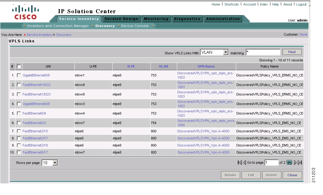
Viewing Discovered Layer 2 VPLS Links
Follow these steps to view discovered Layer 2 VPLS links:
Step 1
The VPLS Links window appears, as shown in Figure 4-52.
Figure 4-52 VPLS Links Window
The VPLS Links window allows you to perform the following tasks:
•
This task is explained in the following steps of this procedure.
•
See Editing Discovered Layer 2 VPLS Links for detailed instructions.
•
See Deleting Discovered Layer 2 VPLS Links for instructions on this task.
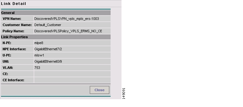
Step 2
The Link Detail window appears, as shown in Figure 4-53.
Figure 4-53 Link Detail Window
The Link Detail window shows the details about the discovered VPN, such as the User-Network Interface (UNI), in a table format.
Step 3
Editing Discovered Layer 2 VPLS Links
You can edit a discovered Layer 2 VPLS link to change the policy that is applied to the service. Follow these steps to edit a Layer 2 VPLS link:
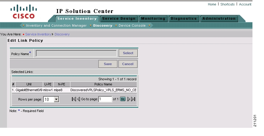
Step 1
The Edit Link Policy window appears, as shown in Figure 4-54.
Figure 4-54 Edit Link Policy Window
Step 2
a.
A list of policies appears.
You can change the list of policies by choosing a filter from the pull-down list in the Show VPN policies with field and/or entering a search mask in the Matching field.
You can filter the policy list by Policy Name, Customer Name, Provider Name, or Global policy name. And you can limit the lists of policies displayed in the selected category by entering a value in the Matching field.
Step 3
Step 4
•
•
Deleting Discovered Layer 2 VPLS Links
Follow these steps to delete a VPLS link:
Step 1
The following message appears:
The selected link(s) will be deleted. Do you really want to Delete?Step 2
If you click OK, the VPLS link(s) are deleted.
Step 3
Saving the L2VPN Metro Ethernet Policy and Initiating Service Creation
After you are finished viewing or editing the discovered L2VPN Metro Ethernet topology, click the Close button to return to the L2VPN Discovery (Ethernet Services) window.
Click the Continue button to initiate the L2VPN Service Discovery process.
The Discovery Workflow window appears and indicates that the L2VPN Service Discovery process is In Progress. The status indicator is yellow.
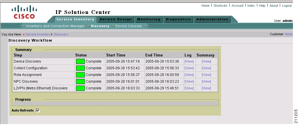
After the L2VPN Service Discovery process is complete, the status indicator changes to green, and the Discovery Workflow window indicates that the L2VPN Service Discovery process is Complete, as shown in Figure 4-55.
Figure 4-55 Discovery Workflow Window with L2VPN Service Discovery Completed
Step 8: Commit Discovered Devices and Services to ISC Repository
Click the Continue button to commit the discovered devices and services to the ISC repository. Prior to this step, discovery workflow stores the discovered devices and services in a temporary repository, which gets committed to ISC only at the last step of discovery workflow.
Step 9: Create and Run a Collect Config Task for the Discovered Devices
Before you view and edit services, follow these steps to run a Create Config task for the devices:
Note
Step 1
The Monitoring window appears.
Step 2
The Tasks window appears.
Step 3
The Create Task window appears.
Step 4
The Collect Config Task window appears.
Step 5
a.
A dialog window appears, listing the devices that were discovered by the Discovery process.
b.
c.
The Collect Config Task window appears again.
d.
e.
You are now ready to view and edit services as described in the following section, Step 10: View and Edit Services
Step 10: View and Edit Services
After you have successfully completed the MPLS VPN and/or L2VPN Metro Ethernet service creation process, you can view the services that were created and modify them using the service requests editors.
Follow these steps to view the L2VPN services:
Step 1
The Service Inventory window is now active.
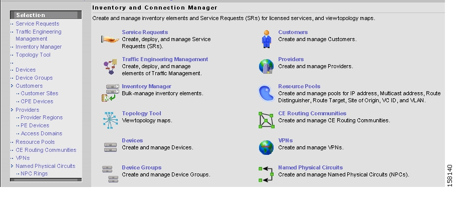
Step 2
The Inventory and Connection Manager window appears, as shown in Figure 4-56.
Figure 4-56 Inventory and Connection Manager Window
Step 3
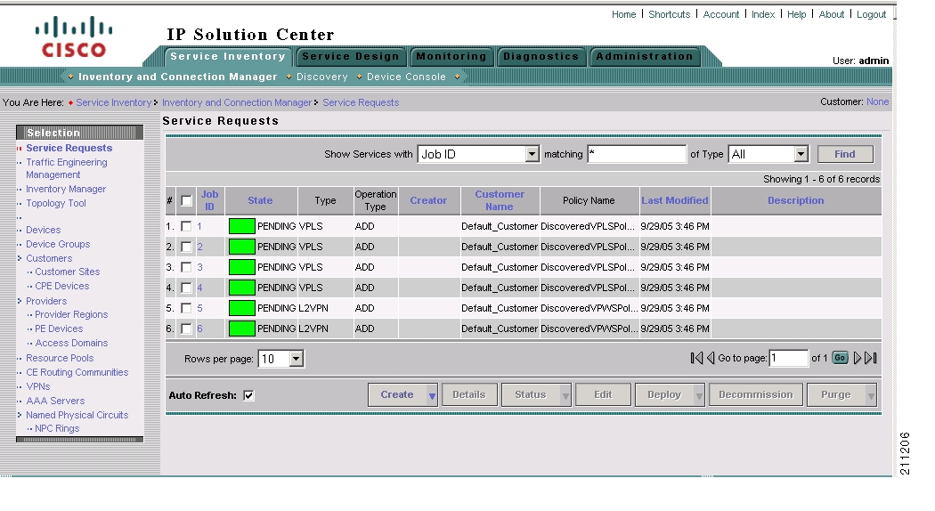
The Service Requests window appears, as shown in Figure 4-57.
Figure 4-57 Service Requests Window
You can modify the service requests shown in the Service Requests window as required.
Note
Step 4
Step 5
![]()
![]()
![]()
![]()
![]()
![]()
![]()
![]()
Posted: Mon Feb 18 15:46:40 PST 2008
All contents are Copyright © 1992--2008 Cisco Systems, Inc. All rights reserved.
Important Notices and Privacy Statement.