|
|

Table Of Contents
Service Inventory —
Inventory and Connection ManagerTraffic Engineering Management
Accessing the Inventory Manager Window
Accessing the Topology Tool for ISC-VPN Topology
Viewing Device and Link Properties
Manually Enabling RTR Responder on Cisco IOS Routers
Editing a Device Configuration
Accessing the Device Groups Window
Accessing the Customers Window
Accessing the Providers Window
Accessing the Resource Pools Window
Creating a Route Distinguisher and Route Target Pool
Creating a Site of Origin Pool
Accessing the CE Routing Communities Window
Creating CE Routing Communities
Deleting CE Routing Communities
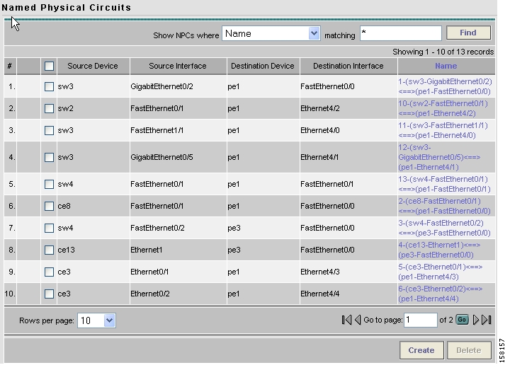
Accessing the Named Physical Circuits Window
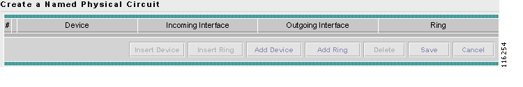
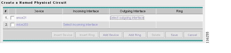
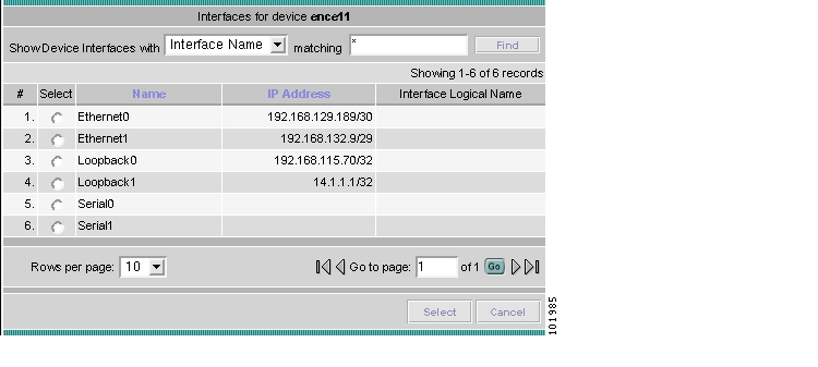
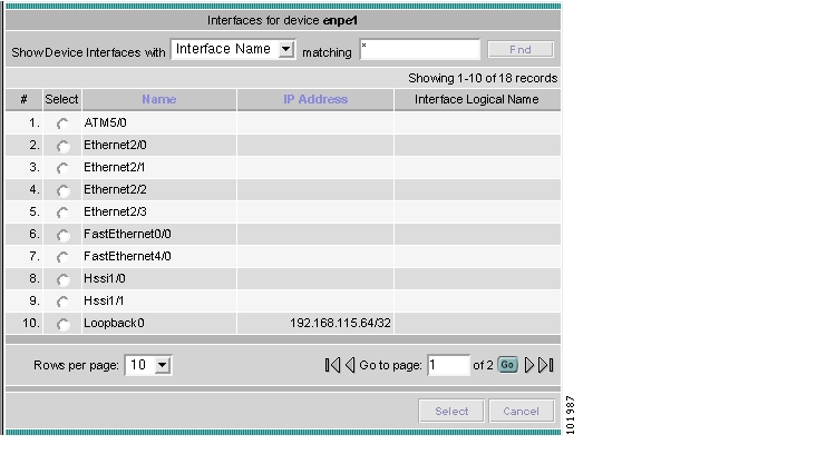
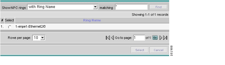
Creating a Named Physical Circuit
Deleting Named Physical Circuits
Service Inventory —
Inventory and Connection Manager
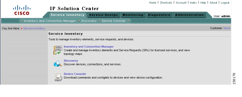
From the Home window of Cisco IP Solution Center (ISC), which appears upon logging in, click the Service Inventory tab and a window as shown in Figure 3-1, " Service Inventory Selections Window," appears.
Figure 3-1 Service Inventory Selections Window
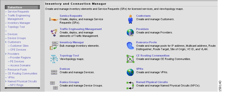
Click on Inventory and Connection Manager and a window as shown in Figure 3-2, " Inventory and Connection Manager Selections Window," appears.
Figure 3-2 Inventory and Connection Manager Selections Window
From the Inventory and Connection Manager window, you can choose any of the following functions:
•
Service Requests Create, deploy, and manage Service Requests (SRs).
•
•
•
•
•
•
•
•
•
•
•
Service Requests
Service Requests are explained in each of the User Guides for each of the applicable licensed services.
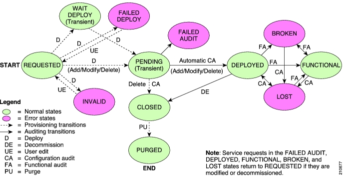
Figure 3-3, " Service Request States Transition Diagram," shows a high-level diagram of the relationships and movement among ISC service request states.
Note
Figure 3-3 Service Request States Transition Diagram
Table 3-1, " Summary of Cisco IP Solution Center Service Request States," describes the functions of each ISC service request state. They are listed in alphabetical order.
Table 3-2, " User Operations on ISC Service Requests," describes user operations and their impact on ISC service requests.
Traffic Engineering Management
Traffic Engineering Management allows you to create, deploy, and manage elements of Traffic Engineering Management. This is explained in detail in the Cisco IP Solution Center Traffic Engineering Management User Guide, 5.0.
Inventory Manager
Inventory Manager provides a method of managing mass changes to inventory and service model data in the ISC provisioning process. In this process, Inventory Manager enables an operator to import network-specific data into the ISC Repository (Repository) in bulk mode.
Inventory Manager performs three primary functions:
•
•
•
Accessing the Inventory Manager Window
To access the Inventory Manager, follow these steps:
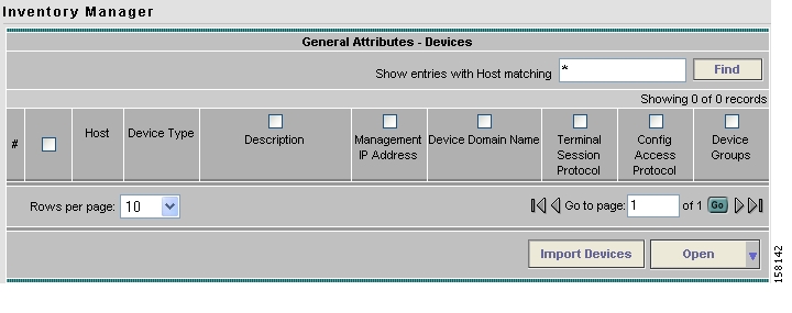
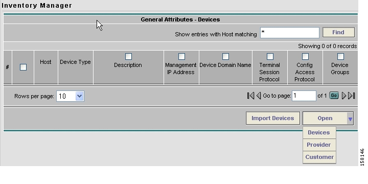
Step 1
Figure 3-4 Inventory Manager Window
From the Inventory Manager window you can import devices or open a list of devices, providers or customers.
Importing Devices
To import a device, it must be in an existing directory on the same server that is running ISC. After a device is imported into the ISC repository, you can assign it to a customer or provider, if desired.
To import devices with configuration files, follow these steps:
Step 1
Step 2
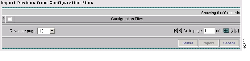
The Import Devices from Configuration Files window appears, as shown in Figure 3-5.
Figure 3-5 Import Devices from Configuration Files Window
Step 3
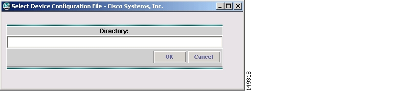
The Select Device Configuration File dialog box appears, as shown in Figure 3-6.
Figure 3-6 Select Device Configuration File Dialog
Step 4
Step 5
Step 6
Step 7
Step 8
The General Attributes window appears with the added information.
Step 9
Opening and Editing Devices
To open device configuration files to bulk edit, follow these steps:
Step 1
Step 2
The Open drop-down list appears. The Open options include the following:
•
Note
•
•
Step 3
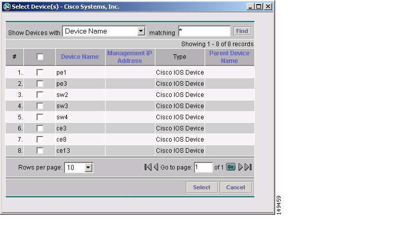
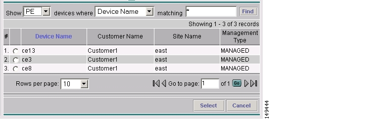
The Select Device window appears, as shown in Figure 3-7.
Figure 3-7 Select Devices Window
Step 4
Step 5
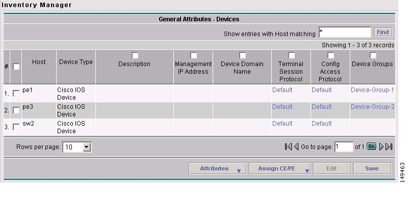
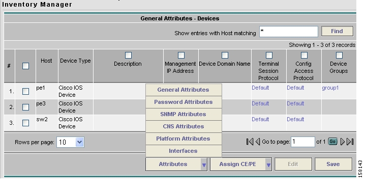
The General Attributes window appears containing information on the selected devices, as shown in Figure 3-8.
Figure 3-8 General Attributes Devices Window
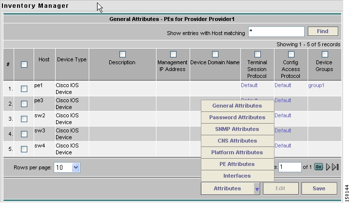
Step 6
The Attributes options appear, as shown in Figure 3-9.
Figure 3-9 Attributes Options Window
Step 7
See the following sections for descriptions of these attribute fields.
Step 8
a.
b.
c.
Step 9
Step 10
The changes are saved.
General Attributes Devices
The General Attributes Devices window appears, as shown in Figure 3-10.
Figure 3-10 General Attributes Devices Window
The General Attributes Devices window contains the following:
•
•
–
–
–
–
•
•
•
•
•
•
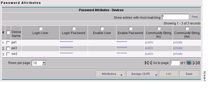
Password Attributes Devices
The Password Attributes Devices window appears, as shown in Figure 3-11.
Figure 3-11 Password Attributes Devices Window
The Password Attributes Devices window contains the following:
•
•
•
•
•
•
•
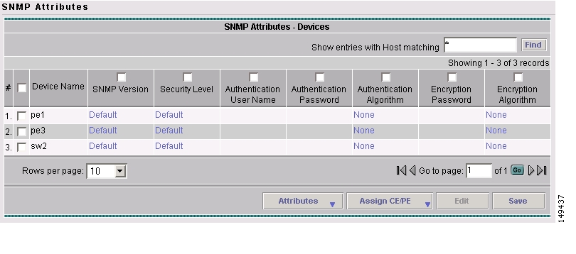
SNMP Attributes Devices
The SNMP Attributes Devices window appears, as shown in Figure 3-12.
Figure 3-12 SNMP Attributes Devices Window
The SNMP Attributes Devices window contains the following:
•
•
•
•
•
•
•
•
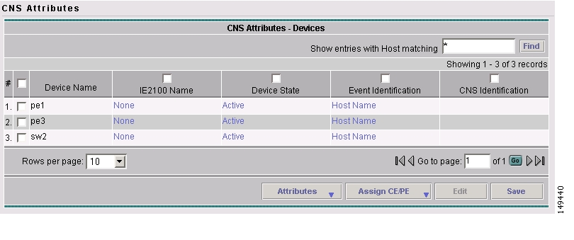
CNS Attributes Devices
The CNS Attributes Devices window appears, as shown in Figure 3-13.
Figure 3-13 CNS Attributes Devices Window
The CNS Attributes Devices window contains the following:
•
•
•
•
•
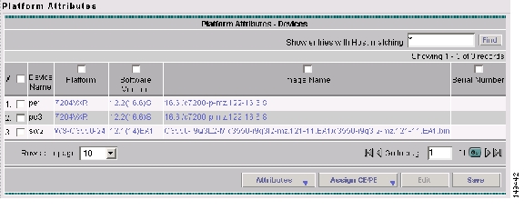
Platform Attributes Devices
The Platform Attributes Devices window appears, as shown in Figure 3-14.
Figure 3-14 Platform Attributes Devices Window
The Platform Attributes Devices window contains the following:
•
•
•
•
•
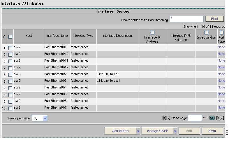
Interfaces Devices
The Interfaces Devices window appears, as shown in Figure 3-15.
Figure 3-15 Interfaces Devices Window
The Interfaces Devices window contains the following:
•
•
•
•
•
•
•
–
–
–
–
–
–
–
–
–
–
–
–
–
–
–
–
–
•
Opening and Editing PEs
To open PE files to bulk edit, follow these steps:
Step 1
Step 2
The Open drop-down list appears. The Open options include the following:
•
•
•
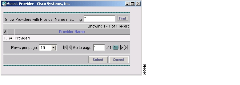
Step 3
The Select Provider window appears, as shown in Figure 3-16.
Figure 3-16 Select Provider Window
Step 4
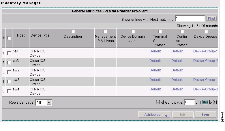
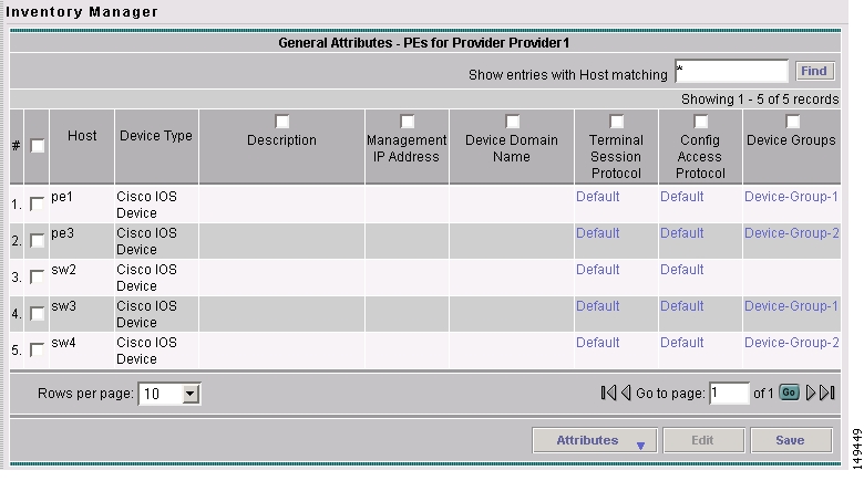
Step 5
The General Attributes Provider window appears showing the PEs assigned to the selected provider, as shown in Figure 3-17.
Figure 3-17 General Attributes Provider Window
Step 6
The Attributes options appear, as shown in Figure 3-18.
Figure 3-18 Attributes Options Window
Step 7
See the following sections for descriptions of these attribute fields.
•
•
Step 8
a.
b.
c.
Step 9
Step 10
The changes are saved.
General Attributes Provider
The General Attributes Provider window appears, as shown in Figure 3-19.
Figure 3-19 General Attributes Provider Window
The General Attributes Provider window contains the following:
•
•
–
–
–
–
•
•
•
•
•
•
Password Attributes Provider
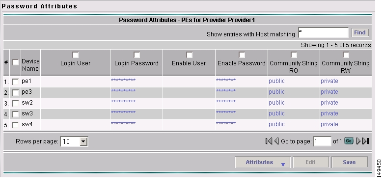
The Password Attributes Provider window appears, as shown in Figure 3-20.
Figure 3-20 Password Attributes Provider Window
The Password Attributes Provider window contains the following:
•
•
•
•
•
•
•
SNMP Attributes Provider
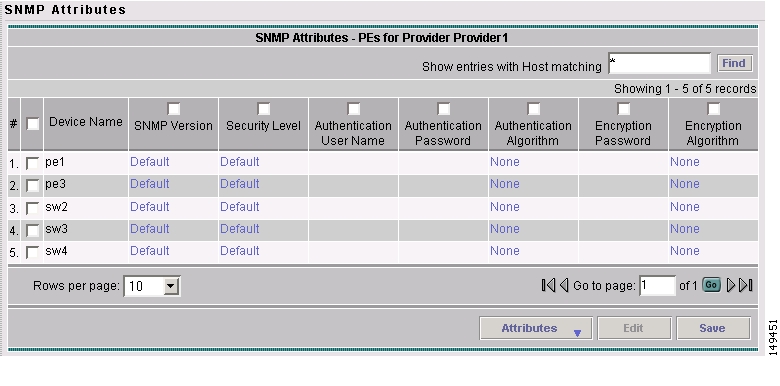
The SNMP Attributes Provider window appears, as shown in Figure 3-21.
Figure 3-21 SNMP Attributes Provider Window
The SNMP Attributes Provider window contains the following:
•
•
•
•
•
•
•
•
CNS Attributes Provider
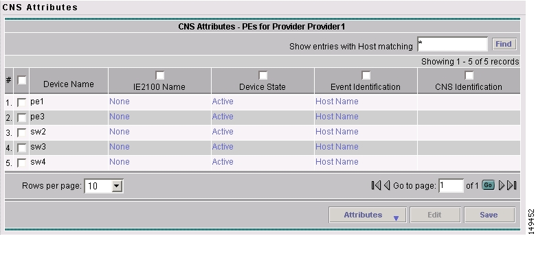
The CNS Attributes Provider window appears, as shown in Figure 3-22.
Figure 3-22 CNS Attributes Provider Window
The CNS Attributes Provider window contains the following:
•
•
•
•
•
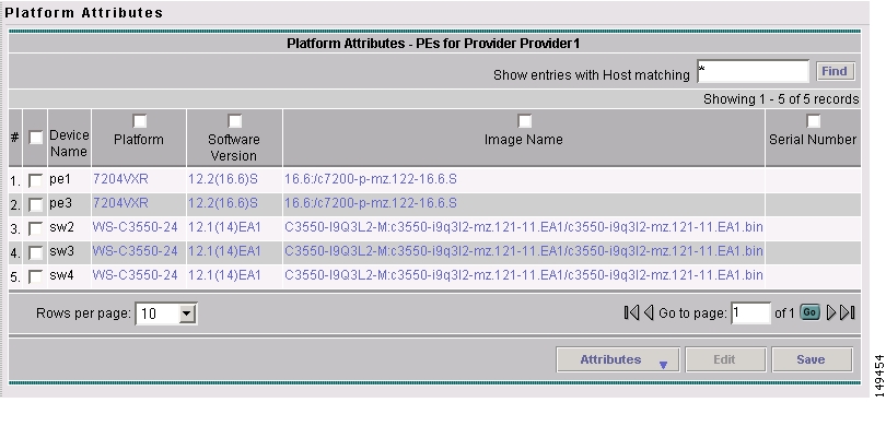
Platform Attributes Provider
The Platform Attributes Provider window appears, as shown in Figure 3-23.
Figure 3-23 Platform Attributes Provider Window
The Platform Provider window contains the following:
•
•
•
•
•
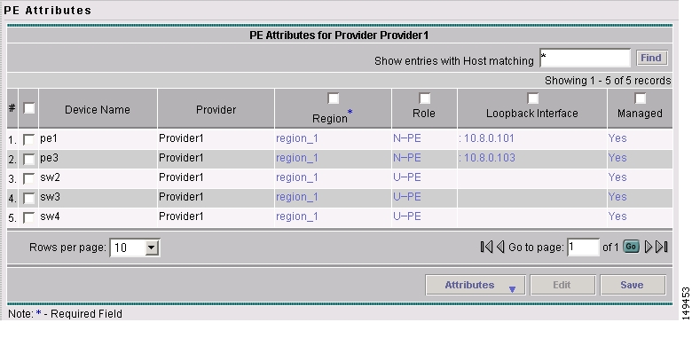
PE Attributes Provider
The PE Attributes Provider window appears, as shown in Figure 3-24.
Figure 3-24 PE Attributes Provider Window
The PE Attributes Provider window contains the following:
•
•
•
•
•
•
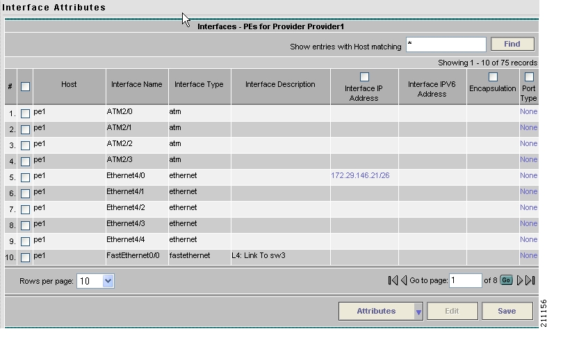
Interfaces Provider
The Interfaces Provider window appears, as shown in Figure 3-25.
Figure 3-25 Interfaces Provider Window
The Interfaces Provider window contains the following:
•
•
•
•
•
•
•
–
–
–
–
–
–
–
–
–
–
–
–
–
–
–
–
–
•
Opening and Editing CEs
To open CE files to bulk edit, follow these steps:
Step 1
Step 2
The Open drop-down list appears. The Open options include the following:
•
•
•
Step 3
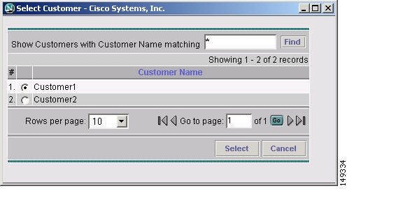
The Select Customer window appears, as shown in Figure 3-26.
Figure 3-26 Select Customer Window
Step 4
Step 5
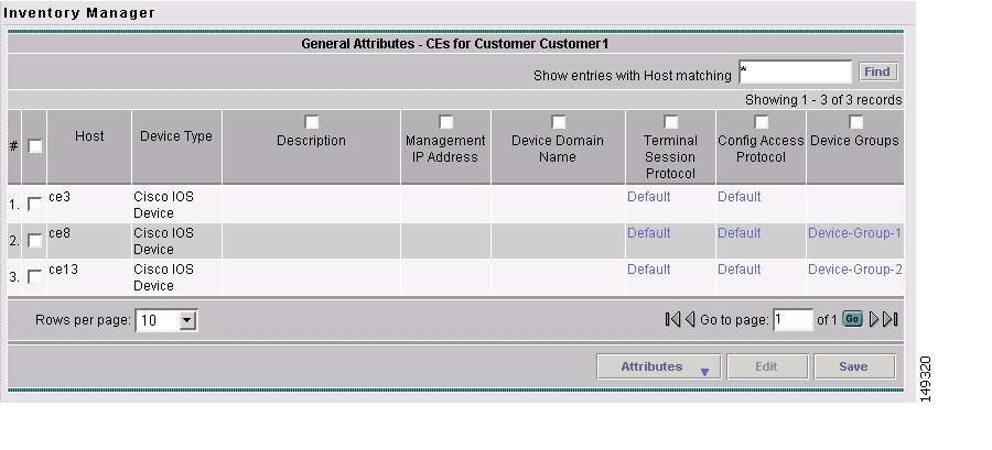
The General Attributes Customer window appears showing the CEs assigned to the selected customer, as shown in Figure 3-27.
Figure 3-27 General Attributes Customer Window
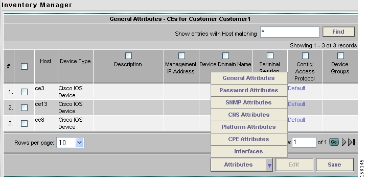
Step 6
The Attributes options appear, as shown in Figure 3-28.
Figure 3-28 Attributes Options Window
Step 7
See the following sections for descriptions of these attribute fields.
•
•
Step 8
a.
b.
c.
Step 9
Step 10
The changes are saved.
General Attributes Customer
The General Attributes Customer window appears, as shown in Figure 3-29.
Figure 3-29 General Attributes Customer Window
The General Attributes Customer window contains the following:
•
•
–
–
–
–
•
•
•
•
•
•
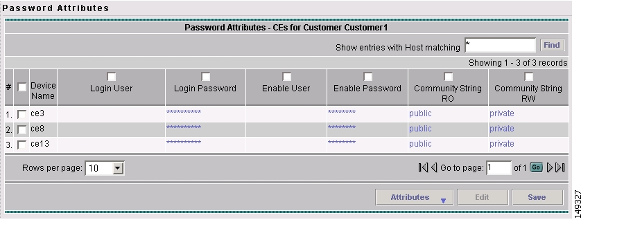
Password Attributes Customer
The Password Attributes Customer window appears, as shown in Figure 3-30.
Figure 3-30 Password Attributes Customer Window
The Password Attributes Customer window contains the following:
•
•
•
•
•
•
•
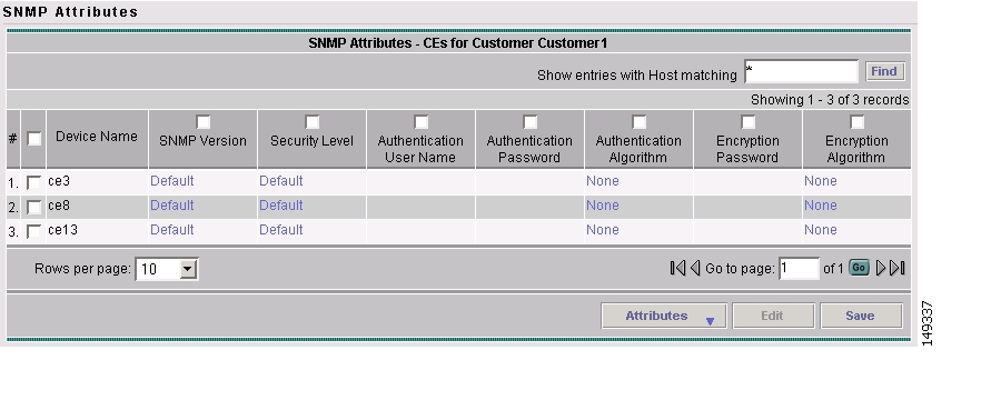
SNMP Attributes Customer
The SNMP Attributes Customer window appears, as shown in Figure 3-31.
Figure 3-31 SNMP Attributes Customer Window
The SNMP Attributes Customer window contains the following:
•
•
•
•
•
•
•
•
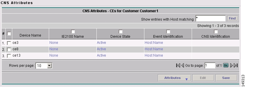
CNS Attributes Customer
The CNS Attributes Customer window appears, as shown in Figure 3-32.
Figure 3-32 CNS Attributes Customer Window
The CNS Attributes Customer window contains the following:
•
•
•
•
•
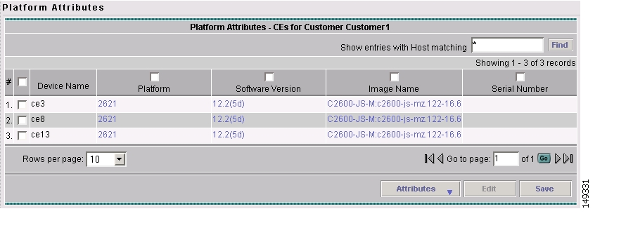
Platform Attributes Customer
The Platform Attributes Customer window appears, as shown in Figure 3-33.
Figure 3-33 Platform Attributes Customer Window
The Platform Customer window contains the following:
•
•
•
•
•
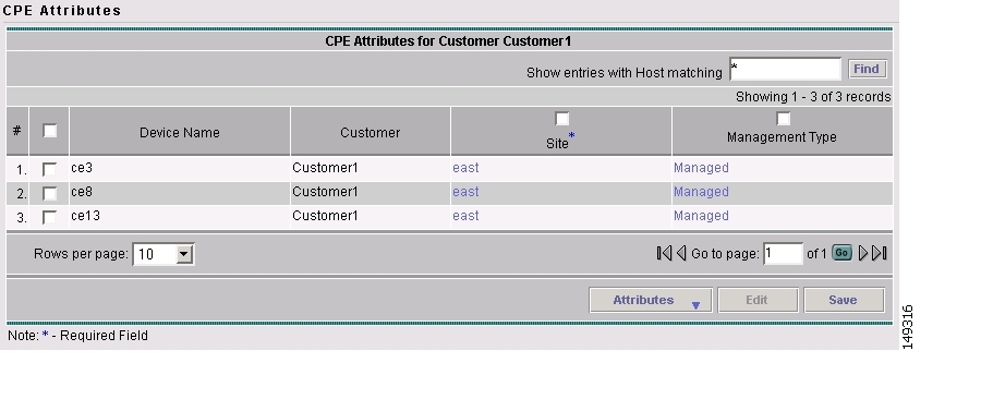
CPE Attributes Customer
The CPE Attributes Customer window appears, as shown in Figure 3-34.
Figure 3-34 CPE Attributes Customer Window
The CPE Attributes Customer window contains the following:
•
•
•
•
Interfaces Customer
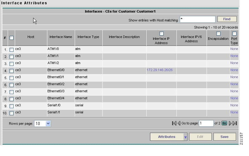
The Interfaces Customer window appears, as shown in Figure 3-35.
Figure 3-35 Interfaces Customer Window
The Interfaces Customer window contains the following:
•
•
•
•
•
•
•
–
–
–
–
–
–
–
–
–
–
–
–
–
–
–
–
–
•
Assigning Devices
To assign a device to a provider or customer, follow these steps:
Step 1
Step 2
The Open drop-down list appears, as shown in Figure 3-37.
Figure 3-36 Open Options Window
Step 3
The Select Device window appears, as shown in Figure 3-37.
Figure 3-37 Select Devices Window
Step 4
Step 5
The General Attributes Devices window appears containing information on the selected devices, as shown in Figure 3-38.
Figure 3-38 General Attributes Devices Window
Step 6
Step 7
The corresponding Select Customer or Select Provider window appears, as shown in Figure 3-39.
Figure 3-39 Select Provider Window
Step 8
Step 9
If you assigned the device to a provider, the PE Attributes window appears. If you assigned the device to a customer, the CPE Attributes window appears.
Step 10
a.
b.
c.
d.
e.
f.
Step 11
Step 12
The PE or CPE is saved to the ISC repository.
Topology Tool
The topology tool provides a graphical view of networks set up through the ISC web client. It gives a graphical representation of the various physical and logical parts of the network, both devices and links.
•
–
•
–
–
Introduction
The topology tool includes three types of views:
•
•
•
In addition, this chapter describes the following features:
•
•
Please note that some details, such as window decorations, are system specific and might appear differently in different environments. However, the functionality should remain consistent.
Launching Topology Tool
To launch the Topology Tool, follow these steps:
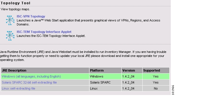
Step 1
Step 2
Figure 3-40 Topology Launch Window
Step 3
Note
Step 4
Figure 3-41 Security Warning Window
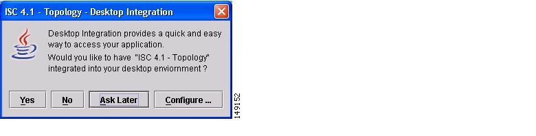
Step 5
Figure 3-42 Topology Desktop Integration Window
The Login window in Figure 3-43, " Log In to ISC Window." appears whether or not a selection has been made in the Desktop Integration window.
Figure 3-43 Log In to ISC Window
Step 6
Conventions
Topology software uses several conventions to visually communicate information about displayed objects. The shape and color of a node representing a device depends on the role of the device, as shown in Table 3-3.
A distinct color scheme is used to highlight the link type as shown in Table 3-4:
Table 3-4 Link Type Color Scheme
(green)
End-to-end wire
(purple)
Attachment circuit
(brown)
MPLS VPN link
Finally, the four patterns shown in Table 3-5 are used to indicate the service request state:
Table 3-5 Link State Pattern Scheme
Deployed, functional, pending
Failed audit, invalid, broken, lost
Wait deploy, requested, failed deploy
Closed
Accessing the Topology Tool for ISC-VPN Topology
Launch the Topology Tool as explained in Figure 3-40, " Topology Launch Window," in the "Launching Topology Tool" section and then use the following steps to access the ISC-VPN Topology tool.
Step 1
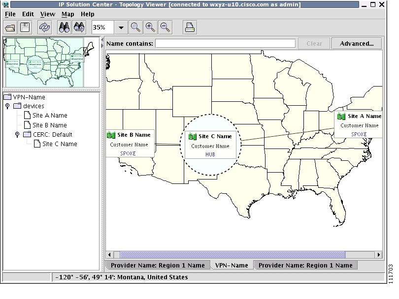
The Topology window shown in Figure 3-44 appears.
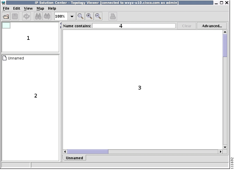
Figure 3-44 Topology Application Window
The application window is divided into four areas, as shown in Figure 3-44:
•
•
•
•
Note
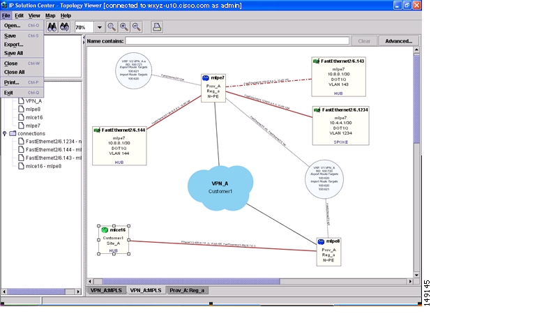
Views are loaded, saved, and closed using the File menu, as shown in Figure 3-45.
Figure 3-45 The File Menu
The File menu contains the following menu items:
•
•
•
•
•
•
•
•
Types of Views
There are three view panes in the topology application and they are described in the following sections:
•
•
•
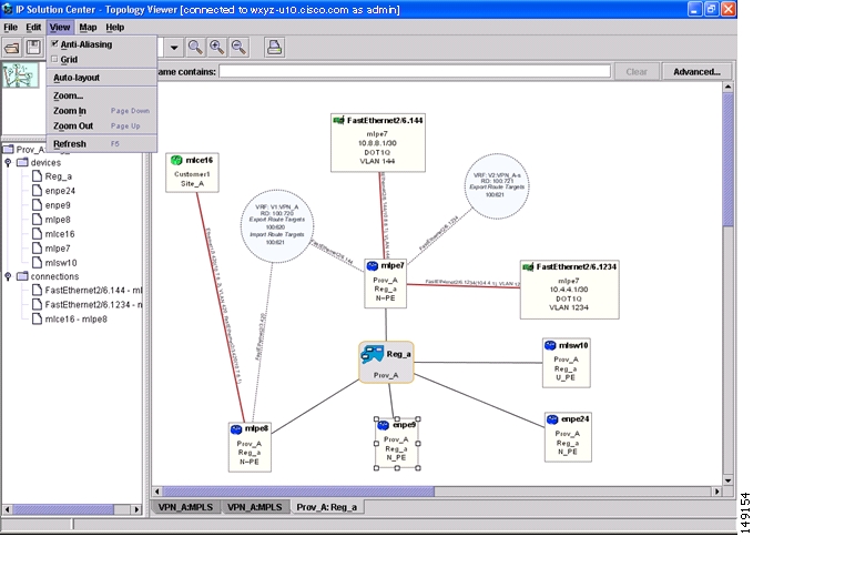
The view attributes can be changed using the View menu, as shown in Figure 3-46.
Figure 3-46 The View Menu
The View menu contains the following menu items:
•
•
•
•
•
•
•
VPN View
The VPN view shows connectivity between devices forming a given VPN. To activate the VPN view, follow these steps:
Step 1
or
click the Open button in the tool bar.
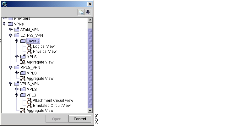
The Folder View window in Figure 3-47 appears displaying a directory tree with available VPNs.
Figure 3-47 Folder View Window
Step 2
Step 3
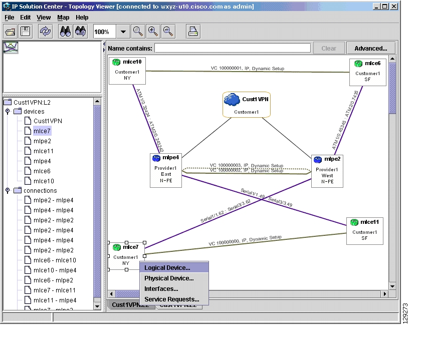
Aggregate View
The Aggregate View, as shown in Figure 3-48, " Aggregate View," shows connectivity between all customer devices, regardless of the type of technology used to connect them.
A single view might show a combination of MPLS, Layer 2, and VPLS. For MPLS, only the Customer Premises Equipment devices (CPEs) are shown.
Figure 3-48 Aggregate View
The Layer 2 VPN might in addition to CPEs show connectivity between Customer Location Edge devices (CLEs) or Provider Edge devices (PE). For VPLS, you see connectivity between CPEs. For missing CPEs, you see connectivity to PEs.
In MPLS Layer 2 VPN, the topology displays Virtual Circuit (VC) with MPLS core (as MPLS string) but with L2TPv3, the topology will display Virtual Circuit (VC) with IP core (as IP string) as shown in Figure 3-49.
Figure 3-49 Virtual Circuit with IP Core
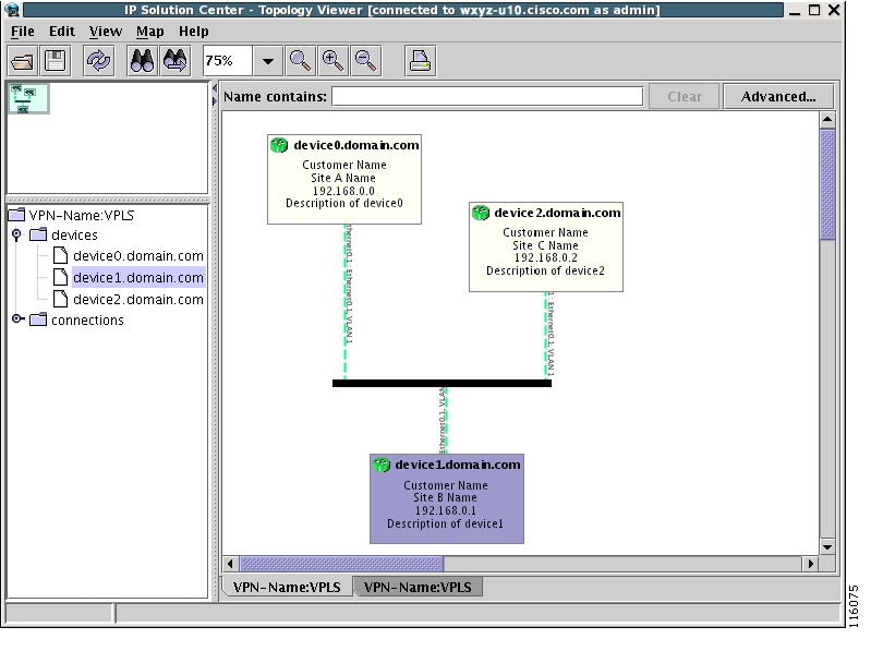
VPLS Topology
In the case of a VPLS topology, you can access an Attachment Circuit View or an Emulated Circuit View. The Attachment Circuit View corresponds to a logical view in other types of VPNs. It shows customer devices connected to a virtual private LAN, as shown in Figure 3-50, " Attachment Circuit View."
Figure 3-50 Attachment Circuit View
The Emulated Circuit View shows the physical connectivity details omitted in the Attachment Circuit View. Connectivity between provider devices and customer devices connected to provider devices, as shown in Figure 3-51, " Emulated Circuit View."
Figure 3-51 Emulated Circuit View
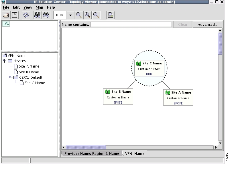
Logical View
The logical view shows connectivity, created through service requests, between PEs and CPEs of a given region.
To activate the logical view, follow these steps:
Step 1
or
click the Open button in the tool bar.
The Folder View window, as shown in Figure 3-47, appears.
Step 2
Step 3
Single-click the Logical View icon and click Open
or
Double-click the Logical View icon.
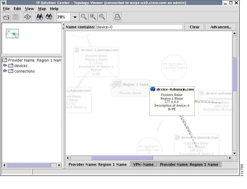
This creates a logical view for the chosen VPN, as shown in Figure 3-52.
Figure 3-52 Logical View
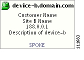
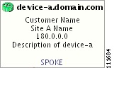
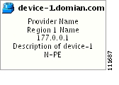
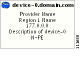
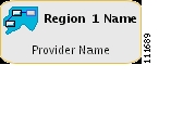
In a created view, the node, usually located in the center of the graph, is the node representing a given region of a provider. The node is annotated with the name of the region and the name of the provider.
Each node directly connected to the regional node represents a PE. The icon of a node depends on the type and the role of the device it represents (see the "Conventions" section).
Each PE is annotated with the fully-qualified device name, provider name, region name, management IP address, description, and role. A right-click on a node displays the details of the logical and physical device, interfaces, and service requests (SR) associated with the node, as shown in Figure 3-53. For the regional node, details are shown in a tabulated form.
Figure 3-53 Device Properties
The various node and link properties are described in detail in Viewing Device and Link Properties.
Likewise, you can right-click on a link to learn about its link properties. For example, when selecting Interfaces... for a sample serial link, a Properties window like the one in Figure 3-54 appears.
Figure 3-54 Interface Properties Window
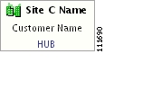
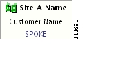
Each PE can be logically connected to one or more CPEs. Such connections are created by either MPLS VPN links or Layer 2 Logical Links. Each such connection is represented by an edge linking the given PE to a CPE. If there are more connections between a particular PE and CPE, all of them are shown. Depending on the state of a connection, the edge is drawn using a solid line (for functioning connections), dotted line (for broken connections), or dashed line (for connections yet to be established).
Depending on the connection type, the connection is drawn as described in Table 3-4 and Table 3-5. Each connection is annotated with the PE Interface Name (IP address), VLAN ID number, CPE Interface Name (IP address).
In the Overview area, a direct connection is drawn between a CPE and a PE, even if a number of devices are forming such a connection.
For more about viewing device properties, see Viewing Device and Link Properties.
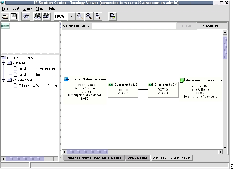
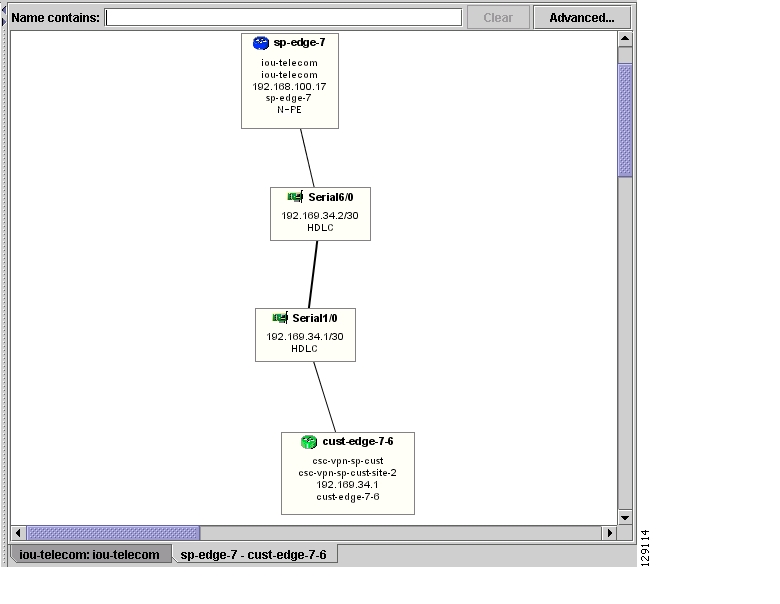
To view the details of a connection, right-click on it and select the Expand option from a pop-up menu. The expanded view, displayed in a new tab, shows all devices and interfaces making a given PE to CPE connection, as shown in Figure 3-55.
Figure 3-55 Detailed Connection View
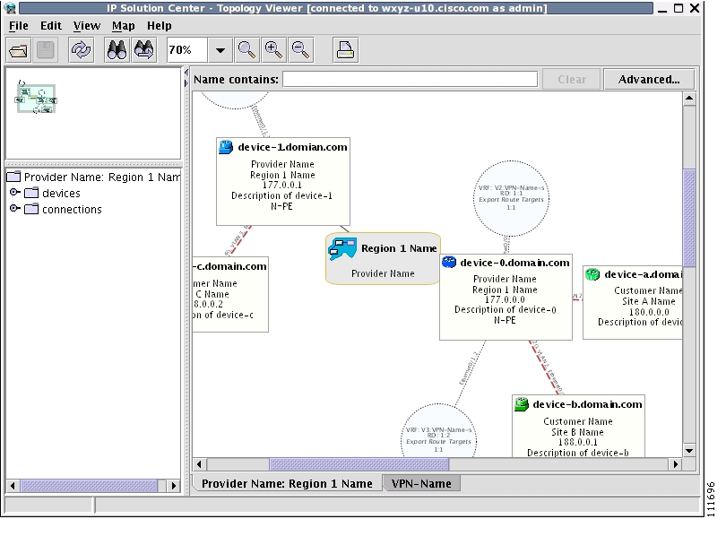
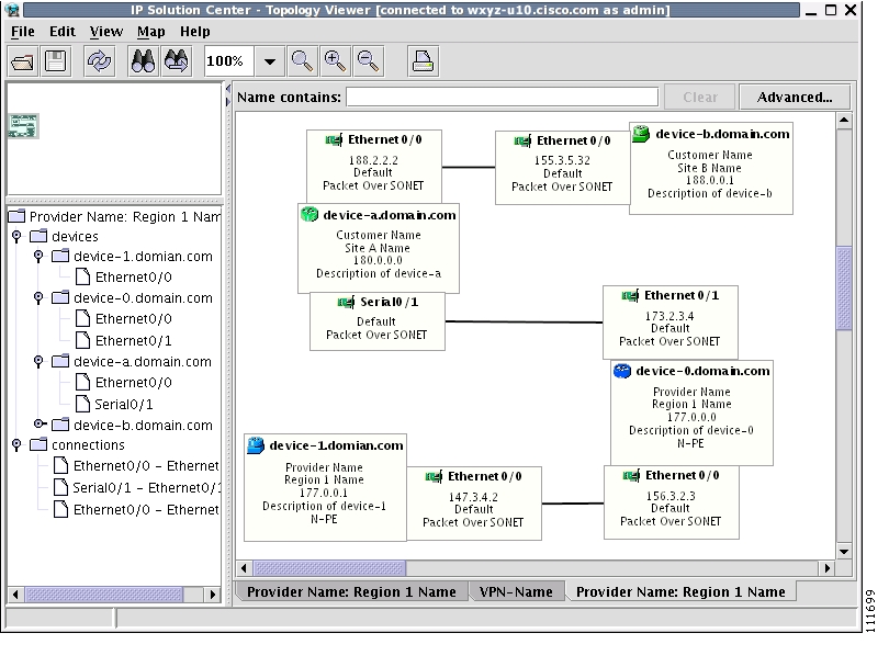
Physical View
A physical view shows all named physical circuits defined for PEs in a given region. Each named physical circuit is represented as a sequence of connections leading from a PE through its interfaces to interfaces of CLEs or CPEs. All physical links between PEs of a given region and their CLEs or CPEs are shown. Since physical links are assumed to be in a perfect operational order, edges are always drawn with solid lines.
To activate the physical view, follow these steps:
Step 1
or
click the Open button in the tool bar.
The Folder View window, as shown in Figure 3-47, appears.
Step 2
Step 3
Single-click the Physical View icon and click Open
or
Double-click the Physical View icon.
This creates a physical view for the chosen VPN, as shown in Figure 3-56.
Figure 3-56 Physical View
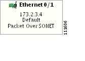
In this view, each device is connected with a thin line to the interfaces it owns. Interfaces are connected to other interfaces with thick lines. If there is more than one connection between two interfaces, they are spaced to show all of them.
The tree shows devices and connections. Each device can be a folder, holding all interfaces connected to it.
Viewing Device and Link Properties
In the logical view, you can view the properties of both devices and links. In the physical view, only properties of physical devices are accessible.
Thus, device properties can be viewed in both the logical and physical views.
Device Properties
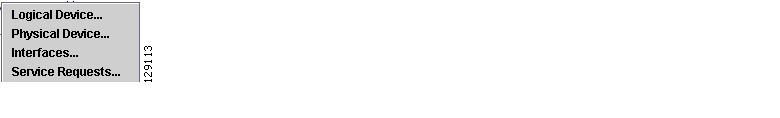
To view the properties of a device, right-click the device. The Device Properties menu in Figure 3-57 appears.
Figure 3-57 Device Properties
The following properties are available:
Logical Device...—View the logical properties of the device.
Physical Device...—View the physical properties of the device.
Interfaces...—View interface properties of the device.
Service Requests...—View service request properties associated with the device.
Logical Device
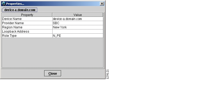
When right-clicking a device and selecting Logical Device..., the logical device properties window in Figure 3-58 appears.
Figure 3-58 Logical Device Properties Window
The logical properties window displays the following information:
Device Name—Name of the device.
Provider Name—Name of the provider whom the device is serving.
Region Name—Name of the provider region.
Loopback Address—IP address of the loopback address.
Role Type—Role assigned to the device.
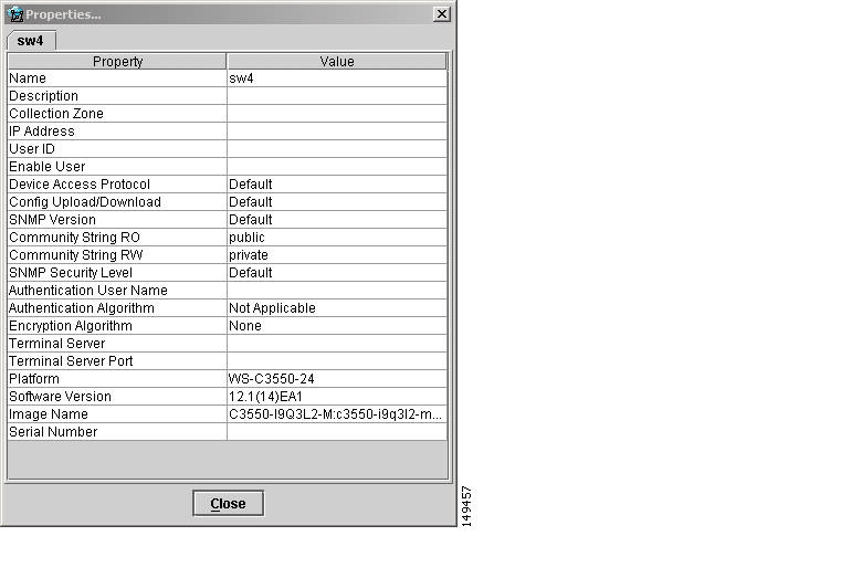
Physical Device
When right-clicking a device and selecting Physical Device..., the physical device properties window in Figure 3-59 appears.
Figure 3-59 Physical Device Properties Window
The physical properties window displays the following information:
Name—Name of the device.
Description—User-defined description of the device.
Collection Zone—Collection zone for device data.
IP Address—IP address of the interface used in the topology.
User ID—User ID for the interface.
Enable User—Password for the interface.
Device Access Protocol—Protocol used to communicate with the device.
Config Upload/Download—Upload/download method for the configuration file.
SNMP Version—Simple Network Management Protocol (SNMP) version on the device.
Community String RO—public or private
Community String RW—public or private
SNMP Security Level—Simple Network Management Protocol (SNMP) security level.
Authentication User Name—User name for performing authentication on the device.
Authentication Algorithm—Algorithm used to perform authentication.
Encryption Algorithm—Encryption algorithm used for secure communication.
Terminal Server—Name of the terminal server.
Terminal Server Port—Port number used by the terminal server.
Platform—Hardware platform.
Software—IOS version or other management software on the device.
Image Name—Boot image for device initialization.
Serial Number—Serial number of the device.
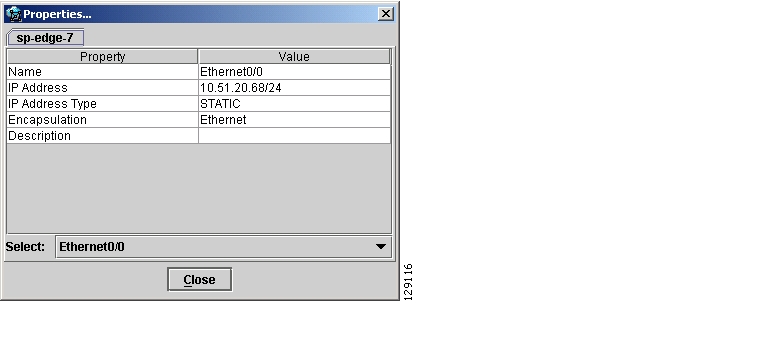
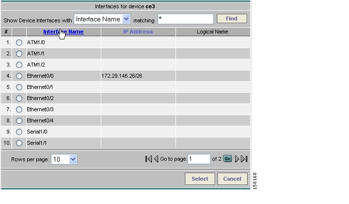
Interfaces
When right-clicking a device and selecting Interfaces..., the interface properties window in Figure 3-60 appears.
Figure 3-60 Device Interface Properties Window
The interface properties window displays the following information:
Name—Name of the device.
IP Address—IP address of the device.
IP Address Type—STATIC or DYNAMIC.
Encapsulation—Encapsulation used on the interface traffic.
Description—Description assigned to the interface, if any.
Select (link)—If a connection is attached to the interface, a drop-down list at the bottom of the window allows you to choose between the interfaces available on the device.
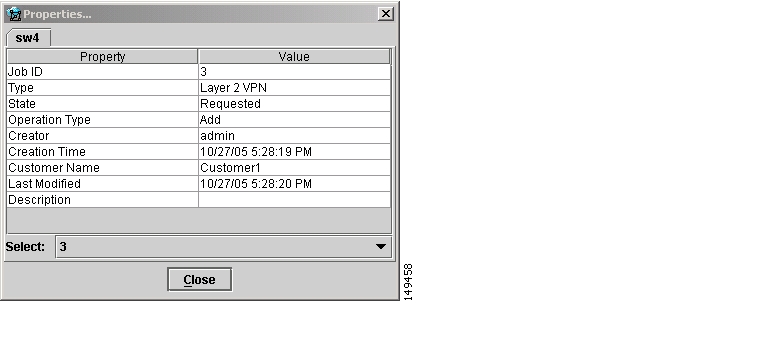
Service Requests
When right-clicking a device and selecting Service Requests..., the service request (SR) properties window in Figure 3-61 appears.
Figure 3-61 Service Request Properties Window
The service request properties window displays the following information:
Job ID—SR identifier.
Type—Protocol type used in the SR.
State—SR state.
Operation Type—Encapsulation used on the interface traffic.
Creator—Description assigned to the interface, if any.
Creation Time—Date and time when the SR was created.
Customer Name—Name of customer associated with the SR.
Last Modified—Date and time when the SR was last modified.
Description—User-defined description of the SR.
Select (SR)—If more than one SR is associated with the interface, the drop-down list at the bottom of the window allows you to choose between these SRs.
Link Properties
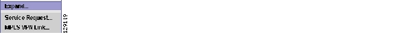
To view the properties of a given link, right-click the link. The Link Properties menu in Figure 3-62 appears.
Figure 3-62 Link Properties
The following options are available:
Expand...—View link details, including devices local to the link not shown in the general topology.
Service Request...—View service request properties associated with the link.
MPLS VPN...—View the MPLS VPN properties of the link. Other link protocol properties than MPLS VPN are currently not available.
Expand
When right-clicking a link and selecting Expand..., the Topology Display will display any devices and connections local to that link. An Expand Link window similar to the one in Figure 3-63 will appear.
Figure 3-63 Expand Link Window
Properties information for devices and links can only be obtained in the master view as described earlier in this section.
Service Request
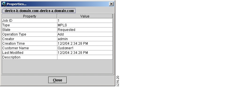
When right-clicking a link and selecting Service Requests..., the service request (SR) properties window in Figure 3-64 appears.
Figure 3-64 Link Service Request Properties Window
The service request properties window displays the following information:
Job ID—SR identifier.
Type—Protocol type used in the SR.
State—SR state.
Operation Type—Encapsulation used on the interface traffic.
Creator—Description assigned to the interface, if any.
Creation Time—Date and time when the SR was created.
Customer Name—Name of customer associated with the SR.
Last Modified—Date and time when the SR was last modified.
Description—User-defined description of the SR.
Select (SR)—If more than one SR is associated with the interface, the drop-down list at the bottom of the window allows you to choose between these SRs.
MPLS VPN
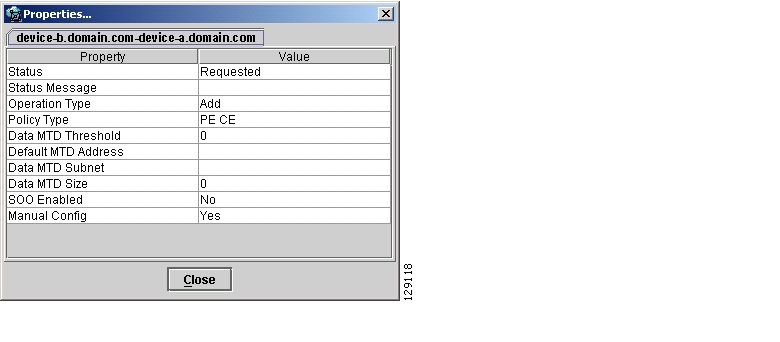
When right-clicking a link that is configured for MPLS VPN and selecting MPLS VPN..., the MPLS VPN properties window in Figure 3-65 appears.
Figure 3-65 Link MPLS VPN Properties Window
The service request properties window displays the following information:
Status—Status of the MPLS VPN link.
Status Message—Displays any error or warning messages.
Operation Type—MPLS operation type.
Policy Type—The policy type applied to the link.
Data MTD Threshold—Memory Technology Driver (MTD) data threshold.
Default MTD Address—Default MTD IP address.
Data MTD Subnet—Data MTD subnet.
Data MTD Size—Data MTD size.
SOO Enabled—Yes or No.
Manual Config—Yes or No.
Filtering and Searching
On large graphs, the amount of detail can be overwhelming. In such cases, filtering might help eliminate unnecessary details, while searching can lead to a prompt location of a device you want to examine further.
Both advanced filtering and searching use the same dialog to enter conditions on nodes to be either filtered or located. The filtering area also allows you to quickly filter viewed objects by name.
Filtering
The topology view can be filtered in two ways, simple and advanced.
Simple Filtering
To perform simple filtering of the view, follow these steps:
Step 1
Step 2
For example, to locate nodes that contain string router in their name you would enter router in area (4) and click Enter. All objects whose name does not contain the entered string are dimmed, as shown in Figure 3-66.
Figure 3-66 Physical View with Dimmed Nodes
Note
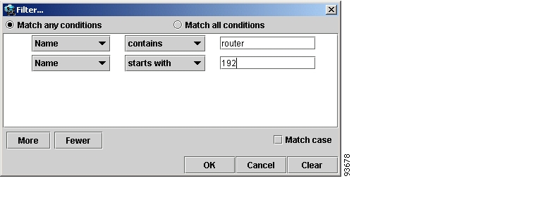
Advanced Filtering
To perform advanced filtering, follow these steps:
Step 1
Step 2
The dialog allows you to enter one or more conditions on filtered nodes. The first drop-down list allows you to specify the attribute by which the filtering is performed. The second allows you to decide how the matching between the value of the attribute and text entered in the third column is performed.
The following matching modes are supported from the drop-down list:
•
•
•
•
•
Figure 3-67 Advanced Filter Dialog
By clicking one of the two radio buttons, Match any conditions or Match all conditions, you can request that any or all of the conditions are matched. In the first case, you can look for devices where, for example, the name contains cisco and the management IP address ends with 204. When all conditions must be met, it is possible to look for devices that, for example, have a given name and platform.
Click More or Fewer to add more rows of conditions or remove existing rows of conditions.
By default, all matches are performed without regard for upper or lower case. However, in some cases it is beneficial to have a more exact matching that takes the case into account. To do so, check the Match case check box.
Step 3
The Clear button allows you to clear all conditions. Clicking Clear followed by OK effectively removes all filtering, restoring all nodes to their default brightness level. If filtering is active, the same can be achieved by clicking Clear in area (4) of the main window, as shown in Figure 3-44.
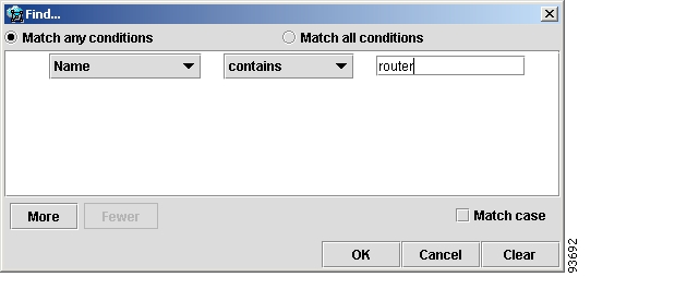
Searching
Searching can be conducted by using the menus or the tool bar. To perform a search, follow these steps:
Step 1
or
Click the Find icon in the main toolbar.
Both approaches bring up the same dialog box, as shown in Figure 3-68.
Again, you can enter one or more conditions to locate the node.
Figure 3-68 Find Dialog Box
Step 2
Step 3
Step 4
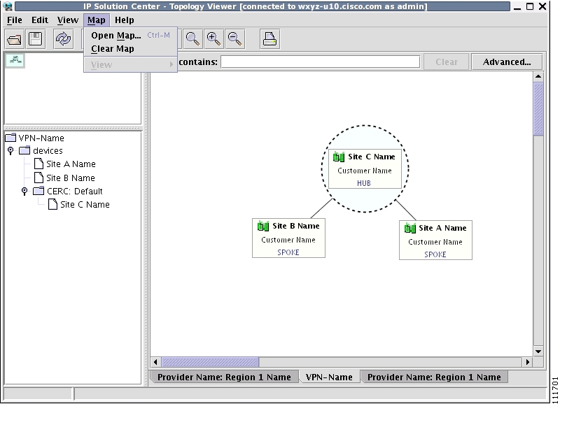
Using Maps
You can associate a map with each view. Currently, the topology viewer only supports maps in the Environmental Systems Research Institute, Inc. (ESRI) shape format. The following sections describe how to load maps and selectively view map layers and data associated with each map.
The map features are accessed from the Map menu shown in Figure 3-69.
Figure 3-69 The Map Menu
The Map menu contains the following menu items:
•
•
•
Loading a map
You might want to set a background map showing the physical locations of the displayed devices. To load a map, follow these steps:
Step 1
or
Press Ctrl-M
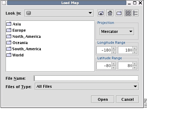
Providing the web map server is running and operational, the Load Map window appears, as shown in Figure 3-70.
Figure 3-70 Load Map Window
Step 2
The right-hand side of the window contains a small control panel, which allows you to select the projection in which a map is shown. A map projection is a projection that maps a sphere onto a plane. Typical projections are Mercator, Lambert, and Stereographic.
For more information on projections, consult the Map Projections section of Eric Weisstein's World of Mathematics at:
http://mathworld.wolfram.com/topics/MapProjections.html
For each projection, you can also select the region of the map to be shown. In most cases, the predefined values should be sufficient. The top level the file hierarchy should contain folders for all major regions, such as Europe, North America, Oceania, and so on.
If desired, make changes to the settings in the Longitude Range and Latitude Range fields.
Step 3
Each folder can contain either complete maps or folders for countries. Each map is clearly distinguished with the Map icon.
Step 4
Selecting the map file and clicking the Open button starts loading it. Maps can consist of several components and thus a progress dialog is shown informing you which part of the map file is loaded.
Layers
Each map can contain several layers. For example most country maps have country, region, and city layers, as shown in Figure 3-71.
Figure 3-71 Map Layers
After a map is loaded, the View submenu of the Map menu is automatically populated for you. A name of each available layer is shown together with the check box indicating visibility of the layer. If a given map shows too many details, you can turn off some or all layers by unchecking the corresponding check box(es). The same submenu can be used to restore visibility of layers.
If an incorrect map is loaded or the performance of the topology tool is unsatisfactory with the map loaded, you can clear the map entirely. To do this, select Clear Map from the Map menu. Maps are automatically cleared if another map is loaded.
Consequently if you want just to load another map, there is no need to clear the existing map. The act of loading a new map does this.
Map data
If map data files are successfully loaded with the map, the right field of the Status bar shows the longitude and latitude location of the cursor on the map. If map objects, such as cities, lakes, and so on, have data associated with them, their names are displayed after the longitude and latitude coordinates.
Node locations
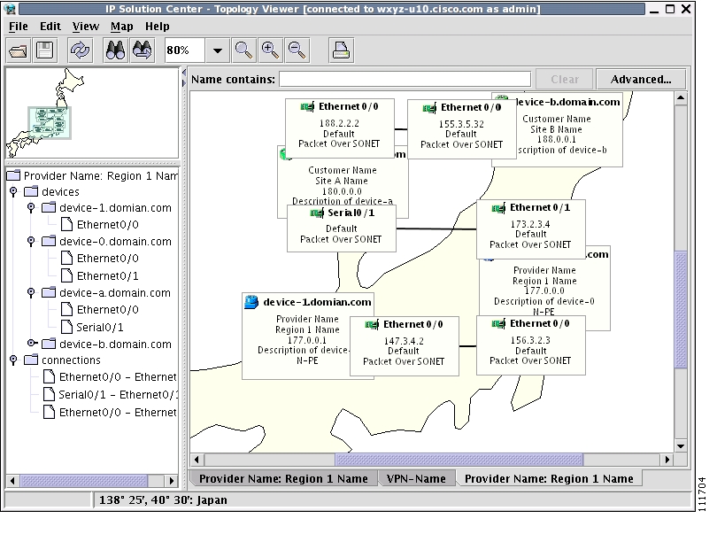
After a map is successfully loaded, the view area is adjusted to fully accommodate it, as shown in Figure 3-72. If nodes shown on the window had longitude and latitude information associated with them, they are moved to locations on the map corresponding to their geographical location. If not, their positions remain unchanged.
However, you can manually move them to the desired location and save the positions for future reference. The next time the image of a given network is loaded, node positions are restored and the map file is loaded.
Figure 3-72 Physical View with a Map of Japan
Adding new maps
You might want to add your own maps to the selection of maps available to the topology application. This is done by placing a map file in the desired directory within the ISC installation. To make this example more accessible, assume that you want to add a map of Toowong, a suburb of Brisbane, the capital of Queensland. The first step to do so is to obtain maps from a map vendor. All maps must be in the ESRI shape file format (as explained at the web site: http://www.esri.com). In addition, a data file might accompany each shape file. Data files contain information about objects whose shapes are contained within the shape file. Let us assume that the vendor provided four files:
•
•
•
•
We must create a map file that informs the topology application about layers of the map. In this case we have two layers: a city and a street layer. The map file, say, Toowong.map, would thus have the following contents:
toowong_citytoowong_streetIt lists all layers that create a map of Toowong. The order is important, as the first file forms the background layer, with other layers placed on top of the preceding layers.
Having obtained shape and data files and having written the map file, decide on its location. As mentioned, Toowong is a suburb of Brisbane, located in Queensland, Australia. All map files must be located in or under the $ISC_HOME/resources/webserver/tomcat/webapps/ipsc-maps/data directory. Since by default this directory contains a directory called Oceania intended for all maps from that region, simply create a path Australia/Queensland/Brisbane under the directory Oceania. Next, place all five files in this location. After this is done, the map is automatically accessible to the topology viewer.
Devices
Every network element that ISC manages must be defined as a device in the system. An element is any device from which ISC can collect information. In most cases, devices are Cisco IOS routers that function as Provider Edge Routers (PEs) or Customer Edge Routers (CEs) in the MPLS VPN.
Note
This section describes how to configure SSH or SSHv2, set up SNMP, manually enable an RTR responder, and create, edit, delete, and configure various types of supported devices. This section includes the following:
•
•
•
•
Configuring SSH or SSHv2
ISC needs a mechanism to securely access and deploy configuration files on devices, which include routers and switches. And, to securely download a configlet and upload a configuration file from a device, Secure Shell (SSH) or SSH version 2(SSHv2) must be enabled.
The following sections describe:
•
•
•
Configuring SSH on Cisco IOS Routers Using a Domain Name
This Cisco IOS router configuration procedure assumes that the router's authentication database is stored locally on the router and not on a TACACS or RADIUS server.
The procedure for configuring SSH on a Cisco IOS router is as follows:
Configuring SSHv1 or SSHv2 on Cisco IOS Routers Using RSA Key Pairs
This Cisco IOS router configuration procedure assumes that the router's authentication database is stored locally on the router and not on a TACACS or RADIUS server.
The procedure for configuring SSHv1 or SSHv2 on a Cisco IOS router is as follows. For more detailed information, go to http://www.cisco.com/en/US/products/ps5845/
products_configuration_guide_chapter09186a00806f9ec4.html#wp1027184.
Configuring SSH or SSHv2 on Cisco IOS XR Routers
This Cisco IOS XR router configuration procedure assumes that the router's authentication database is stored locally on the router and not on a TACACS or RADIUS server.
The procedure for configuring SSHv2 on a Cisco IOS XR router is as follows. For more detailed information, go to http://www.cisco.com/univercd/cc/td/doc/product/software/ios123/123newft/
123t/123t_7/gt_ssh2.htm#wp1027129.
Setting Up SNMP
To work with ISC, SNMP must be configured on each CPE device in the customer network. In ISC, SNMP is used to:
•
•
Two security models are available: SNMPv1/v2c and SNMPv3. Table 3-6 identifies the combinations of security models and levels.
SNMPv3 provides for both security models and security levels. A security model is an authentication strategy that is set up for a user and the group in which the user resides. A security level is the permitted level of security within a security model. A combination of a security model and a security level determines which security mechanism is employed when handling an SNMP packet.
The security features provided in SNMPv3 are as follows:
•
•
•
SNMPv3 objects have the following characteristics:
•
•
•
Setting Up SNMPv1/v2c on Cisco IOS Routers
To determine whether SNMP is enabled, and to set the SNMP community strings on a Cisco IOS router, perform the following steps for each router:
Tip
Setting SNMPv3 Parameters on Cisco IOS Routers
This section describes how to set the SNMPv3 parameters on Cisco IOS routers. SNMPv3 is only supported on IOS crypto images. For Authentication/Encryption, the IOS image must have DES56.
Tip
To check the existing SNMP configuration, use these commands in the router terminal session:
•
•
To set the SNMPv3 server group and user parameters on a Cisco IOS router, perform the following steps.
Note
Manually Enabling RTR Responder on Cisco IOS Routers
Note
To manually enable an RTR Responder on a Cisco IOS router, execute the following steps:
Accessing the Devices Window
The Devices feature is used to create, edit, delete, and configure devices, and e-mail the device owner.
To access the Devices window, follow these steps:
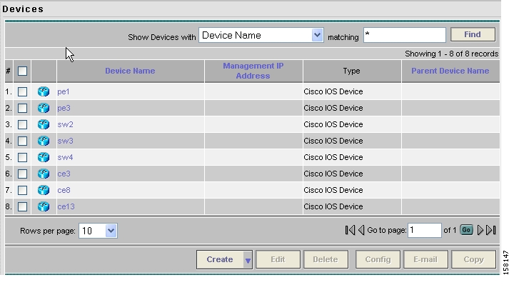
Step 1
Figure 3-73 Devices List Window
The Devices window contains the following:
•
•
•
•
In the Devices window, you can create, edit, delete, or configure devices, e-mail the device owner, or copy using the following buttons:
•
•
•
•
•
•
Creating a Device
From the Create window, you can define different types of devices.
To create a device, follow these steps:
Step 1
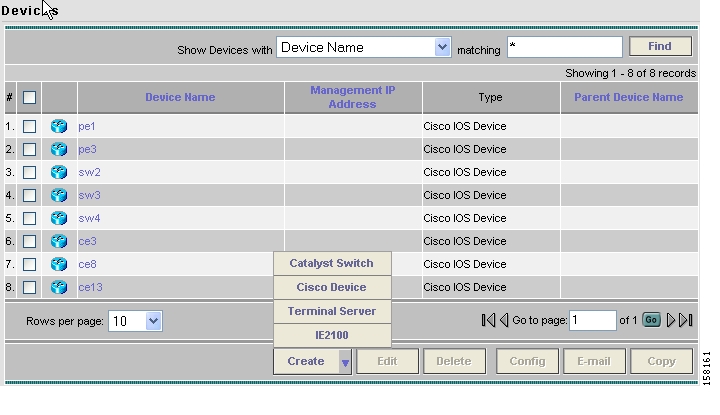
Step 2
The Create options window appears, as shown in Figure 3-74.
Figure 3-74 Create Options Window
The Create options include the following:
•
•
•
•
Step 3
Creating a Catalyst Switch
To create a Catalyst switch, follow these steps:
Step 1
Step 2
Step 3
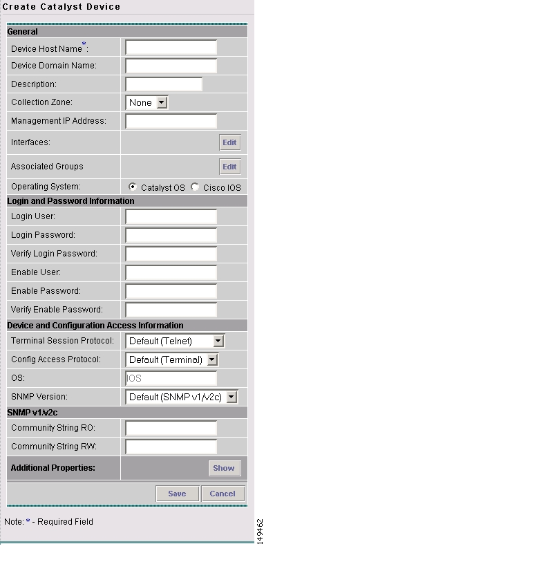
The Create Catalyst Device window appears, as shown in Figure 3-75.
Figure 3-75 Create Catalyst Device Window
The General section of the Create Catalyst Device window contains the following fields:
•
•
•
•
•
•
•
•
The Login and Password Information section of the Create Catalyst Device window contains the following fields:
•
•
•
•
•
•
The Device and Configuration Access Information section of the Create Catalyst Device window contains the following fields:
•
•
•
The SNMP v1/v2c section of the Create Catalyst Device window contains the following fields:
•
•
Step 4
Step 5
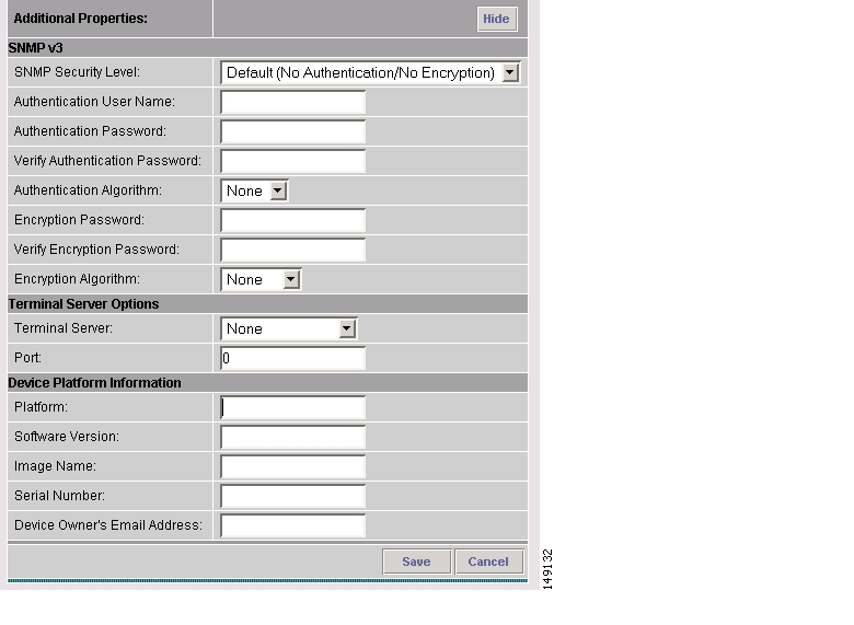
The Additional Properties window appears, as shown in Figure 3-76.
Figure 3-76 Catalyst Device Additional Properties Window
The SNMP v3 section of the Catalyst Device Properties window contains the following fields:
•
•
•
•
•
•
•
•
The Terminal Server Options section of the Catalyst Device Properties window contains the following fields:
•
•
The Device Platform Information section of the Catalyst Device Properties window contains the following fields:
•
•
•
•
•
Step 6
Step 7
The Devices window reappears with the new Catalyst device listed.
Creating a Cisco Device
To create a Cisco device, follow these steps:
Step 1
Step 2
Step 3
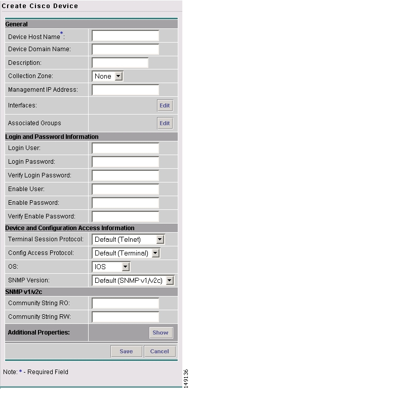
The Create Cisco Device window appears, as shown in Figure 3-77.
Figure 3-77 Create Cisco Device Window
The General section of the Create Cisco IOS Device window contains the following fields:
•
•
•
•
•
•
•
•
The Login and Password Information section of the Create Cisco IOS Device window contains the following fields:
•
•
•
•
•
•
The Device and Configuration Access Information section of the Create Cisco IOS Device window contains the following fields:
•
•
•
•
The SNMP v1/v2c section of the Create Cisco IOS Device window contains the following fields:
•
•
Step 4
Step 5
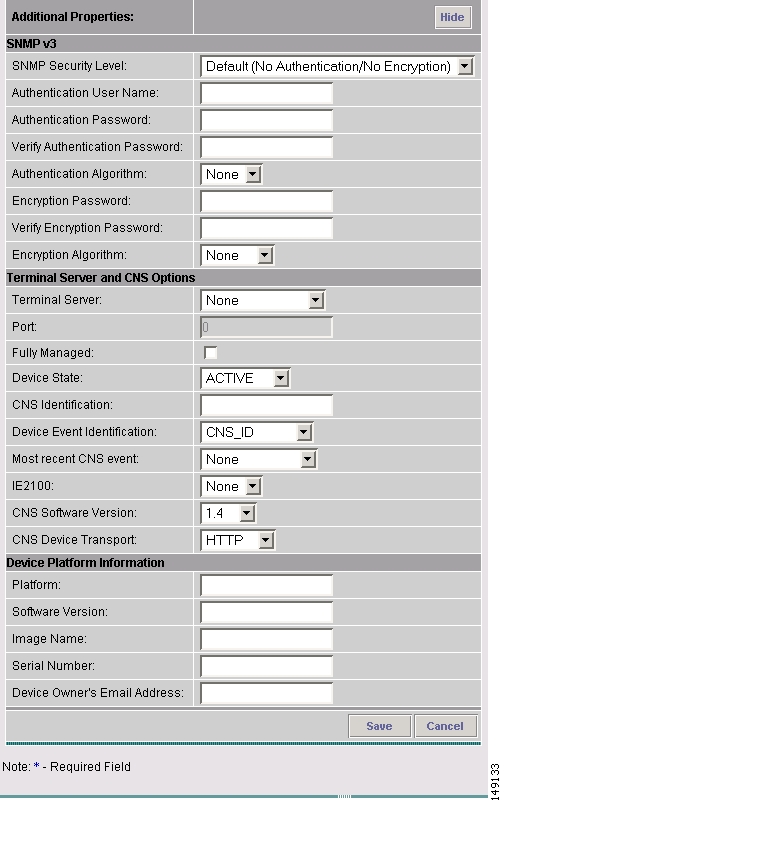
The Additional Properties window appears, as shown in Figure 3-78.
Figure 3-78 Additional Properties for the Cisco Device Properties Window
The SNMP v3 section of the Cisco IOS Device Properties window contains the following fields:
•
•
•
•
•
•
•
•
The Terminal Server and CNS Options section of the Cisco IOS Device Properties window contains the following fields:
•
•
•
•
•
•
•
•
•
•
The Device Platform Information section of the Cisco IOS Device Properties window contains the following fields:
•
•
•
•
•
Step 6
Step 7
The Devices window reappears with the new Cisco IOS device listed.
Creating a Terminal Server
To create a Terminal Server device, follow these steps:
Step 1
Step 2
Step 3
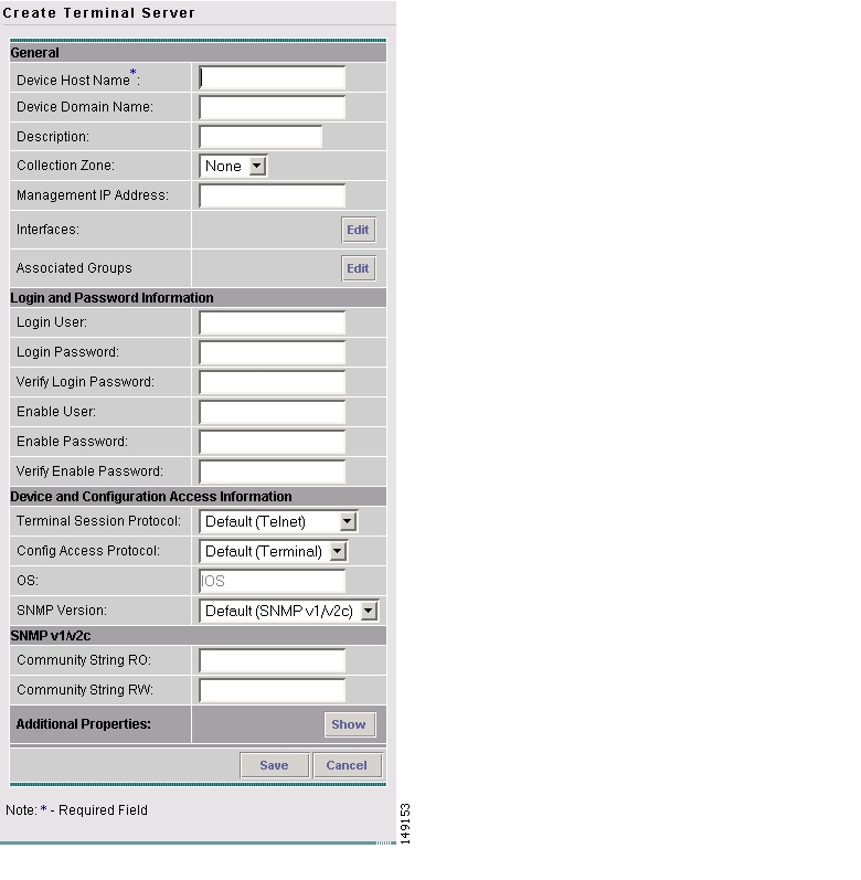
The Create Terminal Server window appears, as shown in Figure 3-79.
Figure 3-79 Create Terminal Server Window
The General section of the Create Terminal Server window contains the following fields:
•
•
•
•
•
•
•
The Login and Password Information section of the Create Terminal Server window contains the following fields:
•
•
•
•
•
•
The Device and Configuration Access Information section of the Create Terminal Server window contains the following fields:
•
•
•
The SNMP v1/v2c section of the Create Terminal Server window contains the following fields:
•
•
Step 4
Step 5
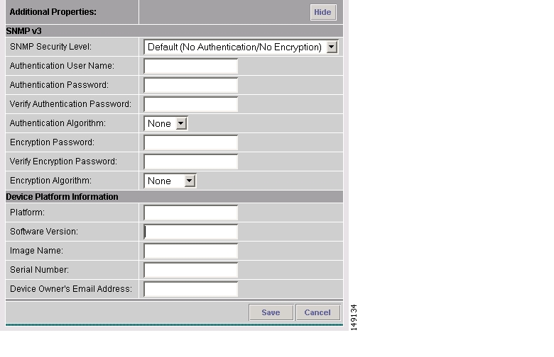
The Additional Properties window appears, as shown in Figure 3-80.
Figure 3-80 Additional Properties for the Terminal Server Device Properties Window
The SNMP v3 section of the Terminal Server Device Properties window contains the following fields:
•
•
•
•
•
•
•
•
The Device Platform Information section of the Terminal Server Device Properties window contains the following fields:
•
•
•
•
•
Step 6
Step 7
The Devices window reappears with the new Terminal Server device listed.
Creating a Cisco CNS IE2100
Note
To create a Cisco CNS IE2100 appliance, follow these steps:
Step 1
Step 2
Step 3
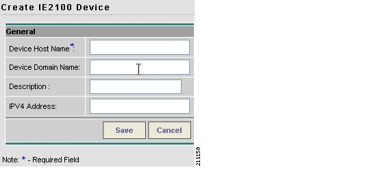
The Create IE2100 Device window appears, as shown in Figure 3-81.
Figure 3-81 Create IE2100 Device Window
The General section of the Create IE2100 Device window contains the following fields:
•
•
•
•
Step 4
Step 5
The Devices window reappears with the new Cisco CNS IE2100 device listed.
Editing a Device
From the Edit window, you can modify the fields that have been specified for a particular device.
To access the Edit window, follow these steps:
Step 1
Figure 3-82 Devices List Window
Step 2
Step 3
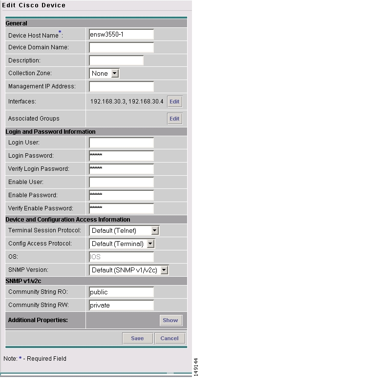
The Edit window appropriate to the type of device selected appears. For example, if you selected a Cisco IOS device the Edit Cisco IOS Device window appears, as shown in Figure 3-83.
Figure 3-83 Editing a Device Window
Step 4
Step 5
The changes are saved and the Devices window reappears.
Deleting Devices
From the Delete window, you can remove selected devices from the database.
To access the Delete window, follow these steps:
Step 1
Figure 3-84 Devices List Window
Step 2
Step 3
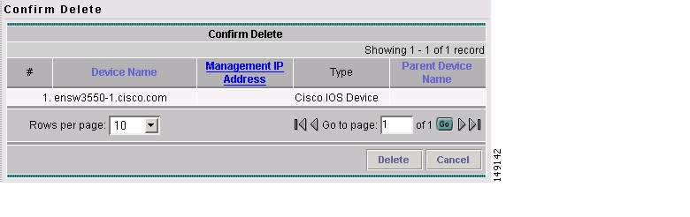
The Confirm Delete window appears, as shown in Figure 3-85.
Figure 3-85 Confirm Delete Window
Step 4
The Devices window reappears with the specified device(s) deleted.
Editing a Device Configuration
From the Config window, you can edit the configuration for a specified device.
To access the Config window, follow these steps:
Step 1
Figure 3-86 Devices List Window
Step 2
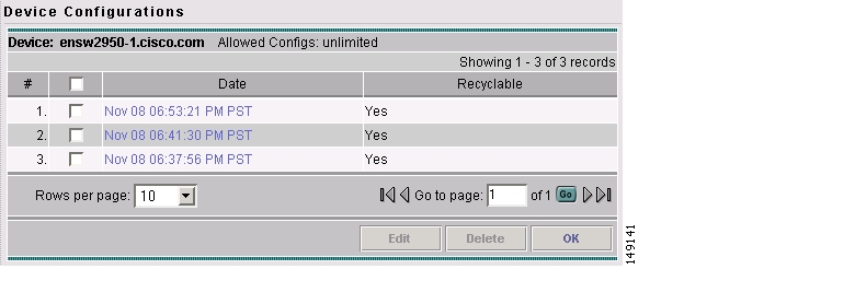
Step 3
The Device Configurations window for the selected device appears, as shown in Figure 3-87.
Figure 3-87 Device Configurations Window
Step 4
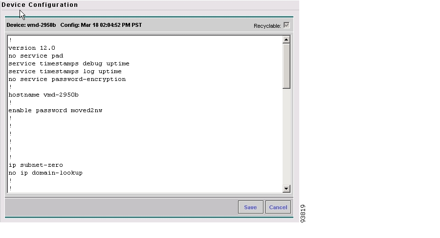
The Device Configuration window for the selected device appears, as shown in Figure 3-88.
Figure 3-88 Device Configuration Window
Step 5
Step 6
The changes are saved and the Device Configurations window reappears.
Step 7
E-mailing a Device's Owner
From the E-mail window, you can send a device report via e-mail to the owners of specified devices.
To access the E-mail window, follow these steps:
Step 1
Figure 3-89 Devices List Window
Step 2
Step 3
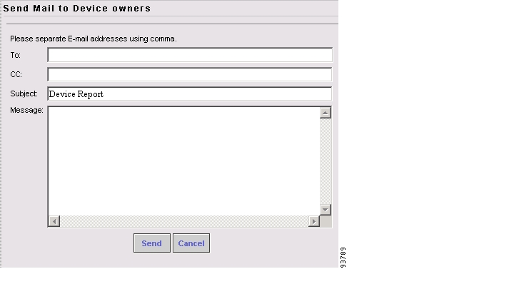
The Send Mail to Device Owners window appears, as shown in Figure 3-90.
Figure 3-90 Send Mail to Device Owners Window
Step 4
Step 5
The e-mail is sent and the Devices window reappears.
Copying a Device
From the Copy window, you receive a copy of the chosen device and can name it and change values.
To access the Copy window, follow these steps:
Step 1
Figure 3-91 Devices List Window
Step 2
Step 3
A window appropriate to the type of device selected to copy appears. You receive an exact copy of the selected device but the Name, Management IP Address, all Interfaces, and VPNSM blades for a Catalyst Switch running Cisco IOS are blanked out and you must fill in the required information and save this new device. See the "Creating a Device" section for specifics.
Device Groups
Every network element that ISC manages must be defined as a device in the system. After you have defined your network elements as devices, you can organize the devices into groups for collection and management purposes.
This section describes how to create, edit, and delete device groups and e-mail device group owners. This section includes the following:
•
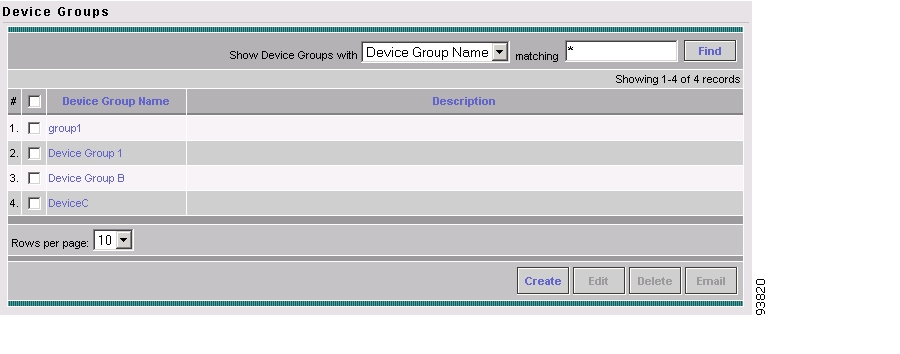
Accessing the Device Groups Window
The Device Groups feature is used to create, edit, and delete device groups and e-mail device group owners.
To access the Device Groups window, follow these steps:
Step 1
Figure 3-92 Device Groups Window
The Device Groups window contains the following:
•
•
From the Device Groups window, you can create, edit, or delete device groups or e-mail device group owners using the following buttons:
•
•
•
•
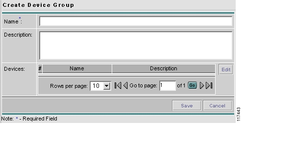
Creating a Device Group
From the Create Device Group window, you can create different device groups.
To create a device group, follow these steps:
Step 1
Step 2
The Create Device Group window appears, as shown in Figure 3-93.
Figure 3-93 Create Device Group Window
The Create Device Group window contains the following fields:
•
•
Step 3
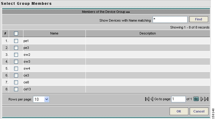
Step 4
The Select Group Members window appears, as shown in Figure 3-94.
Figure 3-94 Select Group Members Window
Step 5
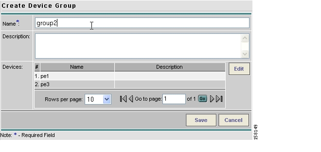
Step 6
The Create Device Group window appears listing the selected devices, as shown in Figure 3-95.
Figure 3-95 Create Device Group Window
Step 7
The Device Groups window reappears with the new device group listed.
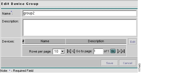
Editing a Device Group
From the Edit Device Group window, you can modify the fields that have been specified for a particular device group.
To access the Edit Device Group window, follow these steps:
Step 1
Step 2
Step 3
The Edit Device Group window appears, as shown in Figure 3-96.
Figure 3-96 Edit Device Group Window
Step 4
Step 5
The changes are saved and the Device Groups window reappears.
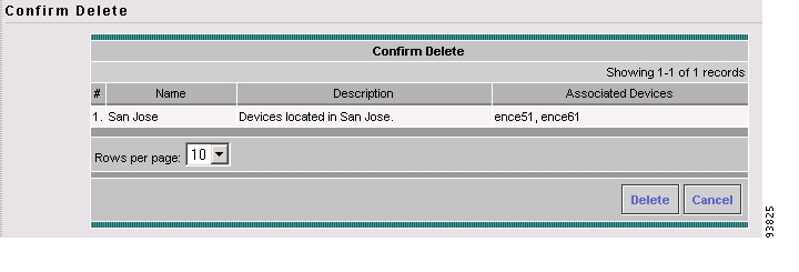
Deleting Device Groups
From the Delete window, you can remove selected device groups from the database.
To access the Delete window, follow these steps:
Step 1
Step 2
Step 3
The Confirm Delete window appears, as shown in Figure 3-97.
Figure 3-97 Confirm Delete Window
Step 4
The Device Groups window reappears with the specified device group(s) deleted.
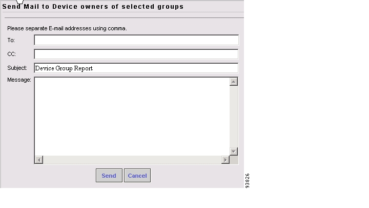
E-mailing a Device Group
From the E-mail window, you can send a device report via e-mail to the owners of specified device groups.
To access the E-mail window, follow these steps:
Step 1
Step 2
Step 3
The Send Mail to Device owners of selected groups window appears, as shown in Figure 3-98.
Figure 3-98 Send Mail to Device Owners of Selected Groups Window
Step 4
Step 5
The e-mail is sent and the Device Groups window reappears.
Customers
A customer site is a set of IP systems with mutual IP connectivity between them without the use of a VPN. Each customer site belongs to exactly one customer. A customer site can contain one or more (for load balancing) edge device routers. This section describes how to create, edit, and delete customers. This section includes the following:
•
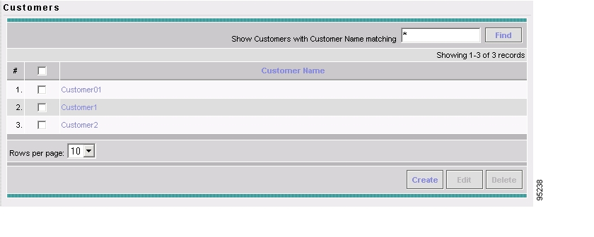
Accessing the Customers Window
The Customers feature is used to create, edit, and delete customers.
To access the Customers window, follow these steps:
Step 1
Figure 3-99 Customers Window
The Customers window contains the following:
•
From the Customers window, you can create, edit, or delete customers using the following buttons:
•
•
•
Creating a Customer
From the Create Customer window, you can create different customers.
To create a customer, follow these steps:
Step 1
Step 2
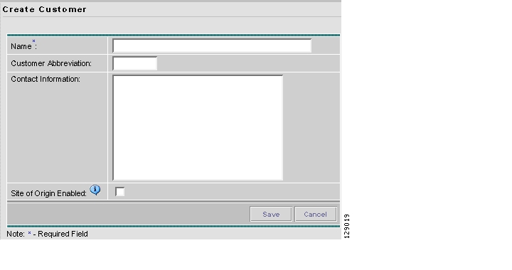
The Create Customer window appears, as shown in Figure 3-100.
Figure 3-100 Create Customer Window
The Create Customer window contains the following fields:
•
•
•
•
Step 3
Step 4
Otherwise, click Save. The changes are then saved and the Customers window reappears.
Editing a Customer
From the Edit Customer window, you can modify the fields that have been specified for a particular customer.
To access the Edit Customer window, follow these steps:
Step 1
Step 2
Step 3
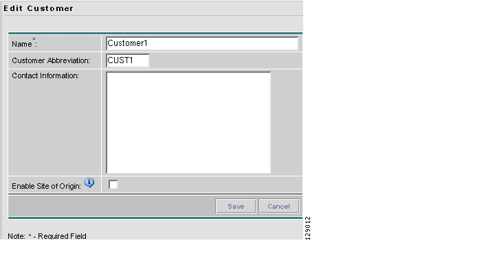
The Edit Customer window appears, as shown in Figure 3-101.
Figure 3-101 Edit Customer Window
Step 4
Step 5
Otherwise, click Save. The changes are then saved and the Customers window reappears.
Deleting Customers
From the Delete window, you can remove selected customers from the database.
To access the Delete window, follow these steps:
Step 1
Step 2
Step 3
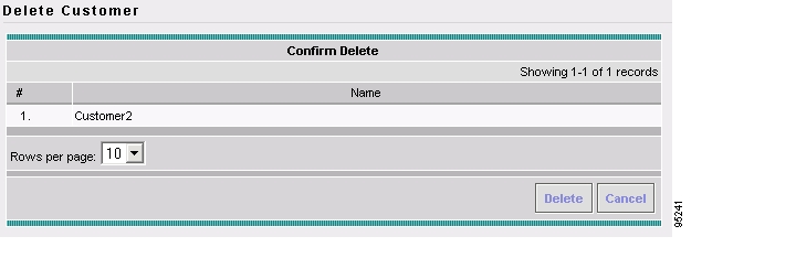
The Confirm Delete window appears, as shown in Figure 3-102.
Figure 3-102 Confirm Delete Window
Step 4
Otherwise, click Delete to confirm that you want to delete the customer(s) listed. The Customers window reappears with the specified customer(s) deleted.
Creating Customer Sites
To access the Customer Sites window, follow these steps:
Step 1
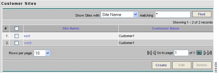
Step 2
The Customer Sites window appears.
Figure 3-103 Customer Sites Window
The Customer Sites window contains the following:
•
•
From the Customer Sites window, you can create, edit, or delete customer sites using the following buttons:
•
•
•
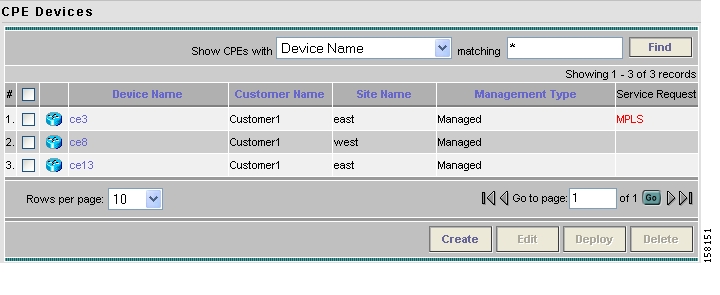
CPE Devices
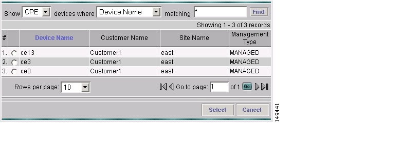
The CPE feature provides a list of CPEs that have been associated with a site through the CPE editor or Inventory Manager. To access the CPE Devices window, follow these steps:
Step 1
Step 2
The CPE Devices window appears.
Figure 3-104 CPE Devices Window
The CPE Devices window contains the following:
•
•
•
•
–
–
–
–
–
–
–
–
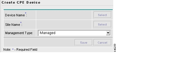
Create CPE Device
This section explains how to create a CPE device.
Step 1
Figure 3-105 Create CPE Device Window
Step 2
Step 3
Step 4
Otherwise, click Save. The changes are saved and the CPE Device window reappears.
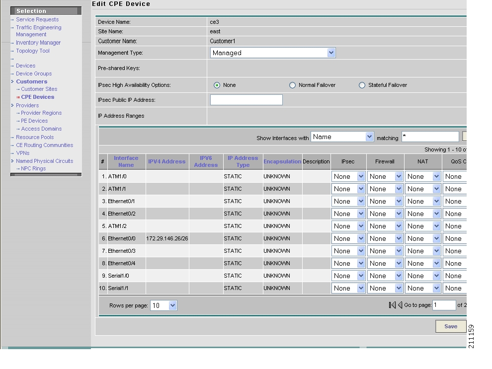
Edit CPE Device
Click Edit to edit a single CPE device selected in Figure 3-104. The result is a window as shown in the example in Figure 3-106, " Edit CPE Device Window," for which you can make changes and Save.
Figure 3-106 Edit CPE Device Window
Delete CPE Device
Click Delete to delete selected CPE device(s) (select by checking the corresponding box). Enabled only if one or more CPE devices are selected. A Confirm Delete window allows you to continue with the deletion or cancel this deletion.
Providers
This section describes how to create and manage providers. This section includes the following:
•
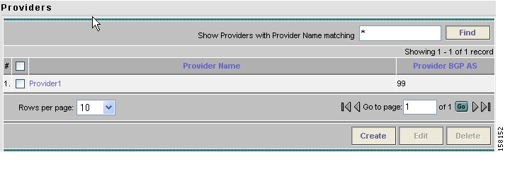
Accessing the Providers Window
The Providers feature is used to create and manage providers.
To access the Providers window, follow these steps:
Step 1
Figure 3-107 Providers Window
The Providers window contains the following:
•
•
From the Providers window, you can create, edit, or delete providers using the following buttons:
•
•
•
Creating a Provider
From the Create Provider window, you can create different providers.
To create a provider, follow these steps:
Step 1
Step 2
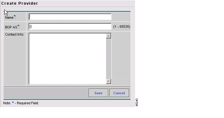
The Create Provider window appears, as shown in Figure 3-108.
Figure 3-108 Create Provider Window
The Create Provider window contains the following fields:
•
•
•
Step 3
Step 4
The Providers window reappears with the new provider listed.
Editing a Provider
From the Edit Provider window, you can modify the fields that have been specified for a particular provider.
To access the Edit Provider window, follow these steps:
Step 1
Step 2
Step 3
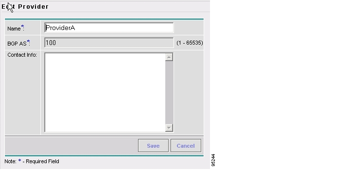
The Edit Provider window appears, as shown in Figure 3-109.
Figure 3-109 Edit Provider Window
Step 4
Step 5
The changes are saved and the Providers window reappears.
Deleting Providers
From the Delete window, you can remove selected providers from the database.
To access the Delete window, follow these steps:
Step 1
Step 2
Step 3
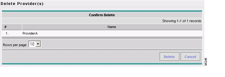
The Confirm Delete window appears, as shown in Figure 3-110.
Figure 3-110 Confirm Delete Window
Step 4
The Providers window reappears with the specified provider(s) deleted.
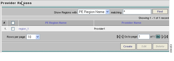
Creating Provider Regions
A Provider Region is considered to be a group of provider edge routers (PEs) within a single BGP autonomous system. The primary objective for defining Provider Regions is to allow a provider to employ unique IP address pools in large Regions, such as Europe, Asia Pacific, and so forth.
To access the Provider Regions window, follow these steps:
Step 1
Step 2
The Provider Regions window appears.
Figure 3-111 Provider Regions Window
The Provider Regions window contains the following:
•
•
From the Provider Regions window, you can create, edit, or delete provider regions using the following buttons:
•
•
•
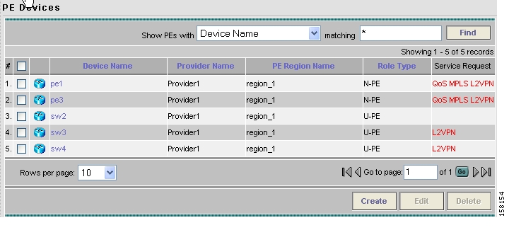
Creating PE Devices
The PE Devices feature provides a list of provider edge routers (PEs) that have been associated with the region, either through the PE editor or Inventory Manager.
To access the PE Devices window, follow these steps:
Step 1
Step 2
The PE Devices window appears.
Figure 3-112 PE Devices Window
The PE Devices window contains the following:
•
•
•
•
From the PE Devices window, you can create, edit, or delete providers using the following buttons:
•
•
Note
•
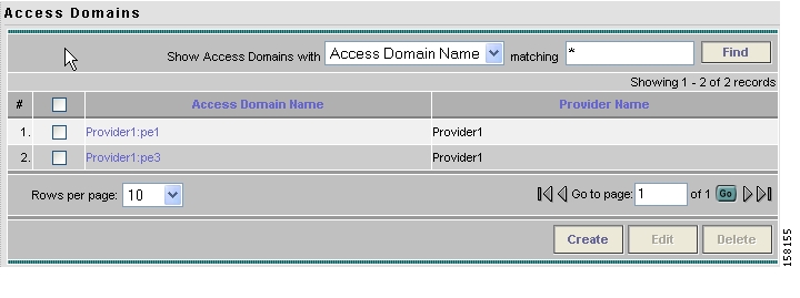
Creating Access Domains
To access the Access Domains window, follow these steps:
Step 1
Step 2
The Access Domains window appears.
Figure 3-113 Access Domains Window
The Access Domains window contains the following:
•
•
From the Access Domains window, you can create, edit, or delete access domains using the following buttons:
•
•
•
Resource Pools
Cisco IP Solution Center enables multiple pools to be defined and used during operations. The following resource pools are available:
•
•
•
•
•
•
•
All these resources, that are made available to the service provider, enable the automation of service deployment.
This section describes how you can create and manage pools for various types of resources. This section includes the following:
•
•
•
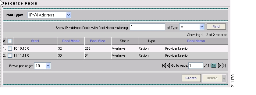
Accessing the Resource Pools Window
The Resource Pools feature is used to create and manage various types of resource pools.
To access the Resource Pools window, follow these steps:
Step 1
Figure 3-114 Resource Pools Window
From the Resource Pools window, you have access to the following buttons:
•
•
•
Creating an IP Address Pool
ISC uses IP address pools to automatically assign IP addresses to PEs and CEs. Each Region has an IP address pool to use for IP numbered addresses (/30 pools) and a separate IP address pool for IP unnumbered addresses (/32 loopback address pools).
Within a VPN or extranet, all IP addresses must be unique. Customer IP addresses must not overlap with the provider's IP addresses. Overlapping IP addresses are only possible when two devices cannot see each other—that is, when they are in isolated VPNs.
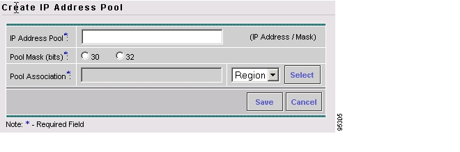
From the Create IP Address Pool window, you can create IP address pools.
To create an IP address pool, follow these steps:
Step 1
Step 2
Step 3
The Create IP Address Pool window appears, as shown in Figure 3-115.
Figure 3-115 Create IP Address Pool Window
The Create IP Address Pool window contains the following fields:
•
•
where:
30 is used for IP numbered address pools (/30)
32 is used for IP unnumbered loopback address pools (/32).
•
Note
Step 4
Step 5
The Resource Pools window reappears with the new IP address pool listed.
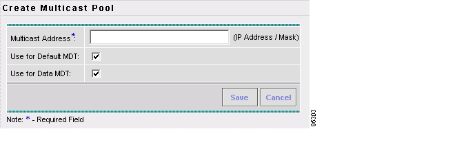
Creating a Multicast Pool
From the Create Multicast Pool window, you can create multicast pools. These pools are global and are not associated with any provider or customer.
To create a multicast pool, follow these steps:
Step 1
Step 2
Step 3
The Create Multicast Pool window appears, as shown in Figure 3-116.
Figure 3-116 Create Multicast Pool Window
The Create Multicast Pool window contains the following fields:
•
•
•
Step 4
Step 5
The Resource Pools window reappears with the new multicast pool listed.
Creating a Route Distinguisher and Route Target Pool
MPLS-based VPNs employ Border Gateway Protocol (BGP) to communicate between PEs to facilitate customer routes. This is made possible through extensions to BGP that carry addresses other than IPv4 addresses. A notable extension is called the route distinguisher (RD).
The purpose of the route distinguisher (RD) is to make the prefix value unique across the network backbone. Prefixes should use the same RD if they are associated with the same set of route targets (RTs) and anything else that is used to select routing policy. The community of interest association is based on the route target (RT) extended community attributes distributed with the Network Layer Reachability Information (NLRI). The RD value must be a globally unique value to avoid conflict with other prefixes.
The MPLS label is part of a BGP routing update. The routing update also carries the addressing and reachability information. When the RD is unique across the MPLS VPN network, proper connectivity is established even if different customers use non-unique IP addresses.
For the RD, every CE that has the same overall role should use a VRF with the same name, same RD, and same RT values. The RDs and RTs are only for route exchange between the PEs running BGP. That is, for the PEs to do MPLS VPN work, they have to exchange routing information with more fields than usual for IPv4 routes; that extra information includes (but is not limited to) the RDs and RTs.
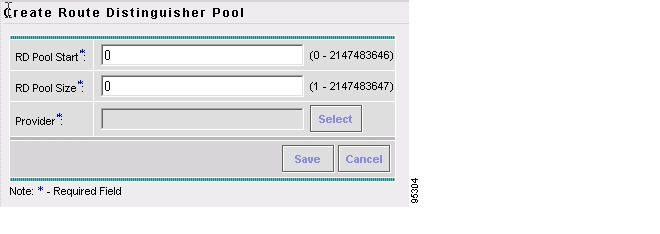
From the Create Route Distinguisher Pool window, you can create route distinguisher pools.
To create a route distinguisher pool, follow these steps:
Step 1
Step 2
Step 3
The Create Route Distinguisher Pool window appears, as shown in Figure 3-117.
Figure 3-117 Create Route Distinguisher Pool Window
The Create Route Distinguisher Pool window contains the following fields:
•
•
•
Step 4
Step 5
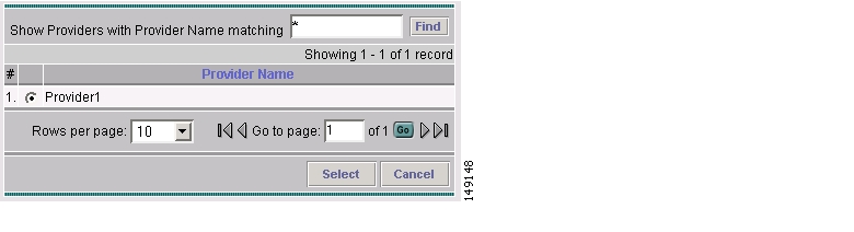
The Provider for new Resource Pool window appears, as shown in Figure 3-118.
Figure 3-118 Provider for New Resource Pool Window
Step 6
Step 7
The Resource Pools window reappears with the new route distinguisher pool listed.
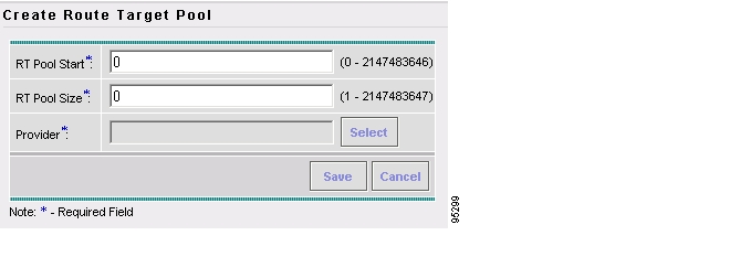
To create a Route Target Pool, follow these steps:
Step 1
Step 2
Step 3
The Create Route Target Pool window appears, as shown in Figure 3-119.
Figure 3-119 Create Route Target Pool Window
The Create Route Target Pool window contains the following fields:
•
•
•
Step 4
Step 5
The Provider for new Resource Pool window appears, as shown in Figure 3-120.
Figure 3-120 Provider for New Resource Pool Window
Step 6
Step 7
The Resource Pools window reappears with the new route target pool listed.
Creating a Site of Origin Pool
In MPLS VPN, CE sites use private/public AS numbers and when one AS number is used for each VPN, all sites belonging to the same VPN share the same private/public AS number. The default BGP behavior is to drop any prefix if its own AS number is already in the AS path. As a result, a customer site does not learn prefixes of a remote site in this situation. AS-OVERRIDE must be configured (if there are hub sites involved, ALLOWAS-IN must be configured) to allow those prefixes to be sent by PE routers but a routing loop can occur.
For example, CE1 and CE2 belong to the same customer VPN and have the same AS number 65001. The AS path between two customer sites is 65001 - 1234 - 65001 and prefixes cannot be exchanged between customer sites because AS 65001 is already in the path. To solve this problem, AS-OVERRIDE options are configured on PE routers; but it introduces a routing loop into the network without using extended community site of origin attributes.
Site of origin is a concept in MPLS VPN architecture that prevents routing loops in sites that are multi-homed to the MPLS VPN backbone and in sites using AS-OVERRIDE in conjunction. Site of origin is a type of BGP extended community attribute used to identify a prefix that originated from a site so that the re-advertisement of that prefix back to the site can be prevented. This attribute uniquely identifies the site from which the PE router learned the route. Site of origin is tagged at PE in peering with BGP neighbors using an inbound route-map and works in conjunction with BGP CE-PE routing protocol.
Site of origin must be unique per customer site per VPN/customer (when these sites are multi-homed). Therefore, the same value of site of origin must be used on PE routers connected to the same CE router or to the same customer site.
Note
From the Create Site of Origin Pool window, you can create site of origin pools.
To create a site of origin pool, follow these steps:
Step 1
Step 2
Step 3
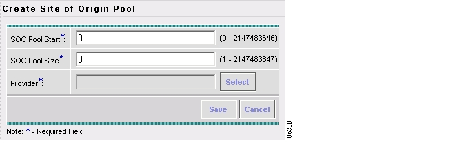
The Create Site of Origin Pool window appears, as shown in Figure 3-121.
Figure 3-121 Create Site of Origin Pool Window
The Create Site of Origin Pool window contains the following fields:
•
•
•
Step 4
Step 5
The Provider for new Resource Pool window appears, as shown in Figure 3-122.
Figure 3-122 Provider for New Resource Pool Window
Step 6
Step 7
The Site of Origin pools window reappears with the new route target pool listed.
Creating a VC ID Pool
From the Create VC ID Pool window, you can create VC ID pools. These pools are global and are not associated with any provider or customer
To create a VC ID pool, follow these steps:
Step 1
Step 2
Step 3
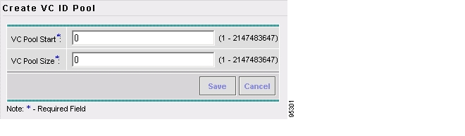
The Create VC ID Pool window appears, as shown in Figure 3-123.
Figure 3-123 Create VC ID Pool Window
The Create VC ID Pool window contains the following fields:
•
•
Step 4
Step 5
The VC ID Pools window reappears with the new VC ID pool listed.
Creating a VLAN Pool
From the Create VLAN Pool window, you can create VLAN pools.
To create a VLAN pool, follow these steps:
Step 1
Step 2
Step 3
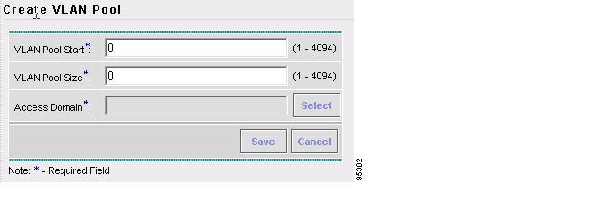
The Create VLAN Pool window appears, as shown in Figure 3-124.
Figure 3-124 Create VLAN Pool Window
The Create VLAN Pool window contains the following fields:
•
•
•
Step 4
Step 5
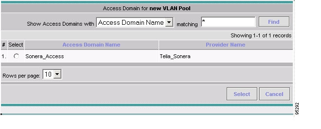
The Access Domain for new VLAN Pool window appears, as shown in Figure 3-125.
Figure 3-125 Access Domain for new VLAN Pool Window
Step 6
Step 7
The VLAN Pools window reappears with the new VLAN pool listed.
Deleting Resource Pools
From the Resource Pool window, you can delete specific resource pools.
To delete resource pools, follow these steps:
Step 1
Step 2
Step 3
Step 4
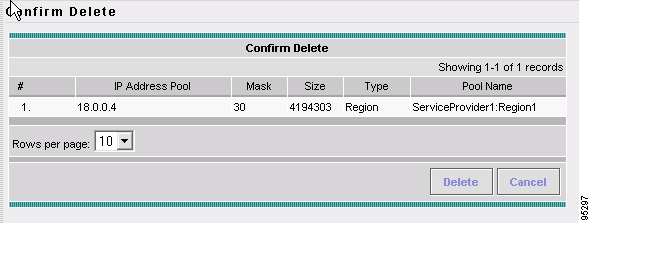
The Confirm Delete window appears, as shown in Figure 3-126.
Figure 3-126 Confirm Delete Window
Step 5
The Resource Pools window reappears with the specified pool(s) deleted.
CE Routing Communities
A VPN can be organized into subsets called CE routing communities, or CERCs. A CERC describes how the CEs in a VPN communicate with each other. Thus, CERCs describe the logical topology of the VPN. Cisco IP Solution Center can be employed to form a variety of VPN topologies between CEs by building hub and spoke or full mesh CE routing communities. CERCs are building blocks that allow you to form complex VPN topologies and CE connectivity.
The most common types of VPNs are hub-and-spoke and full mesh.
•
•
These two basic types of VPNs—full mesh and hub and spoke—can be represented with a single CERC. Whenever you create a VPN, the Cisco IP Solution Center software creates one default CERC for you. This means that until you need advanced customer layout methods, you will not need to define new CERCs. Up to that point, you can think of a CERC as standing for the VPN itself—they are one and the same. If, for any reason, you must override the software's choice of route target values, you can do so only at the time you create a CERC in the Cisco IP Solution Center software.
To build very complex topologies, it is necessary to break down the required connectivity between CEs into groups, where each group is either fully meshed, or has a hub and spoke pattern. (Note that a CE can be in more than one group at a time, if each group has one of the two basic patterns.) Each subgroup in the VPN wants its own CERC. Any CE that is only in one group just joins the corresponding CERC (as a spoke if necessary). If a CE is in more than one group, then you can use the Advanced Setup choice during provisioning to add the CE to all the relevant groups in one service request. Given this information, the provisioning software does the rest, assigning route target values and VRF tables to arrange exactly the connectivity the customer requires. You can use the Topology tool to double-check the CERC memberships and resultant VPN connectedness.
Cisco IP Solution Center supports multiple CEs per site and multiple sites connected to the same PE. Each CERC has unique route targets (RT), route distinguisher (RD), and VPN Routing and Forwarding instance (VRF) naming. After provisioning a CERC, it is a good idea to run the audit reports to verify the CERC deployment and view the topologies created by the service requests. The product supports linking two or more CE routing communities in the same VPN.
This section describes how you can create and manage CE routing communities. This section includes the following:
•
•
•
Accessing the CE Routing Communities Window
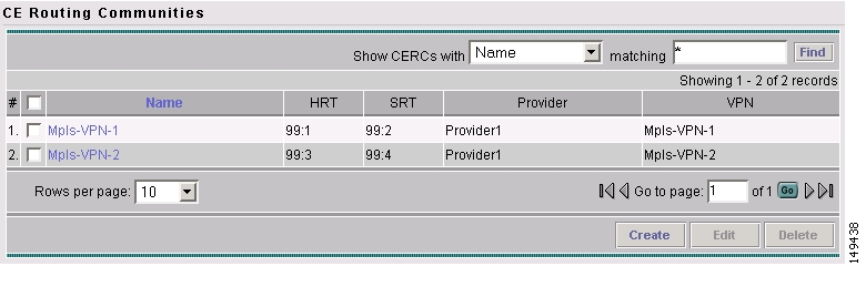
The CE Routing Communities feature is used to create and manage CERCs.
To access the CE Routing Communities window, follow these steps:
Step 1
Figure 3-127 CE Routing Communities Window
From the CE Routing Communities window, you can create, edit, or delete CE routing communities using the following buttons:
•
•
•
Creating CE Routing Communities
When you create a VPN, the Cisco IP Solution Center software creates one default CE routing community (CERC) for you. But if your network topology and configuration require customized CERC definitions, you can define CERCs customized for your network.
Tip
Each subgroup in the VPN wants its own CERC. Any CE that is only in one group just joins the corresponding CERC (as a spoke if necessary). If a CE is in more than one group, then you can use the Advanced Setup choice during provisioning to add the CE to all the relevant groups in one service request. Given this information, Cisco IP Solution Center does the rest, assigning route target values and VRF tables to arrange the precise connectivity the customer requires.
To create a CE routing community, follow these steps:
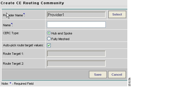
Step 1
Step 2
The Create CE Routing Community window appears, as shown in Figure 3-128.
Figure 3-128 Create CE Routing Community Window
Step 3
a.
The Select Provider dialog box is displayed.
b.
c.
d.
e.
By default, the Auto-pick route target values check box is checked. If you uncheck the check box, you can enter the Route Target values manually.
Caution
Step 4
After creating the CERC, you can add it to the VPN.
Deleting CE Routing Communities
From the CE Routing Community window, you can delete specific CERCs.
To delete CERC(s), follow these steps:
Step 1
Step 2
Step 3
The Confirm Delete window appears.
Step 4
The CE Routing Communities window reappears with the specified CERC(s) deleted.
VPNs
At its simplest, a virtual private network (VPN) is a collection of sites that share the same routing table. A VPN is also a framework that provides private IP networking over a public infrastructure such as the Internet. In Cisco IP Solution Center: MPLS VPN Management, a VPN is a set of customer sites that are configured to communicate through a VPN service. A VPN is defined by a set of administrative policies.
A VPN is a network in which two sites can communicate over the provider's network in a private manner; that is, no site outside the VPN can intercept their packets or inject new packets. The provider network is configured such that only one VPN's packets can be transmitted through that VPN—that is, no data can come in or out of the VPN unless it is specifically configured to allow it. There is a physical connection from the provider edge network to the customer edge network, so authentication in the conventional sense is not required.
This section describes how you can create and manage pools for various types of resources. This section includes the following:
Accessing the VPNs Window
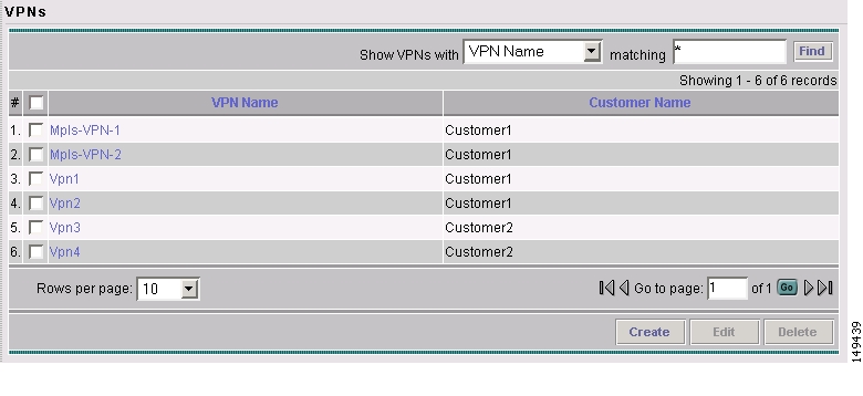
The VPN feature is used to create and manage various types of VPNs.
To access the VPN window, follow these steps:
Step 1
Figure 3-129 VPNs Window
From the VPNs window, you can create, edit, or delete VPNs using the following buttons:
•
•
•
Creating a VPN
To create a VPN, follow these steps:
Step 1
Step 2
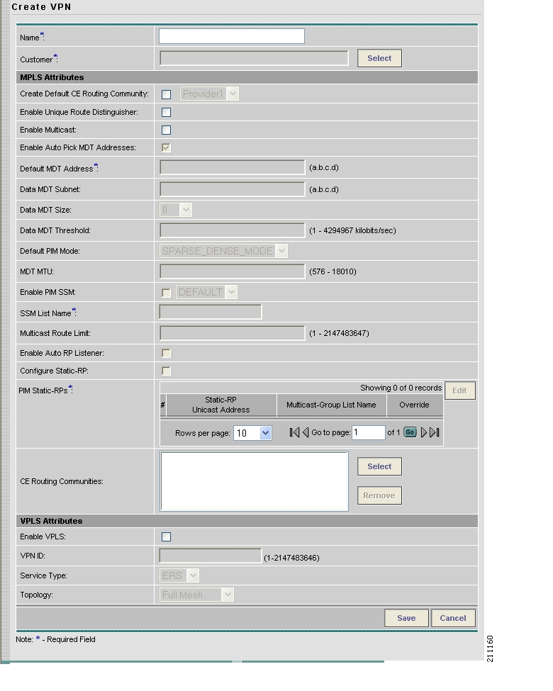
The Create VPN window appears, as shown in Figure 3-130.
Figure 3-130 Create VPN Window
Step 3
a.
b.
c.
d.
e.
f.
g.
An IP address that starts with the binary prefix 1110 is identified as a multicast group address. There can be more than one sender and receiver at any time for a given multicast group address. The senders send their data by setting the group address as the destination IP address. It is the responsibility of the network to deliver this data to all the receivers in the network who are listening to that group address.
Note
h.
i.
j.
k.
MDT refers to a multicast distribution tree (MDT). The MDT defined here carries multicast traffic from customer sites associated with the multicast domain.
l.
The data MDT contains a range of multicast group addresses and a bandwidth threshold. Thus, whenever a CE behind a multicast-VRF exceeds that bandwidth threshold while sending multicast traffic, the PE sets up a new data MDT for the multicast traffic from that source. The PE informs the other PEs about this data MDT and, if they have receivers for the corresponding group, the other PEs join this data MDT.
m.
n.
o.
p.
q.
r.
s.
The Select CE Routing Communities dialog box is displayed.
t.
You return to the Create VPN dialog box, where the new CERC selection is displayed, along with its hub route target (HRT) and spoke route target (SRT) values.
u.
v.
w.
x.
y.
Step 4
You have successfully created a VPN, as shown in the Status display in the lower left corner of the VPNs dialog box.
Deleting VPNs
From the VPNs window, you can delete specific VPNs.
To delete VPN(s), follow these steps:
Step 1
Step 2
Step 3
The Confirm Delete window appears.
Step 4
The VPNs window reappears with the specified VPN(s) deleted.
Named Physical Circuits
Named physical circuits (NPCs) are named circuits that describe a physical connection between a CPE or U-PE and an N-PE. The intermediate nodes of the NPCs can either be CPE or PE. They can be connected in a circular fashion forming a ring of devices, which is represented by an entity known as NPC Rings. NPC Rings represent the circular topology between devices (CPE or PE) to the Named Physical Circuits. To create an NPC, you must specify how the source CPE/U-PE and the destination N-PE are connected and specify the intermediate nodes.
The connectivity of the NPCs is defined by specifying a set of devices serving as physical links; each device has two interfaces that are part of the NPC connections. The Incoming Interface defines the interface from the CE direction. The Outgoing Interface defines the interface toward the PE direction.
You can also add (meaning after the chosen device) or insert (meaning before the chosen device) an NPC Ring in the link.
Keep in mind the following when you are creating an NPC:
•
•
This section describes how you can create and delete NPCs and create, edit, and delete NPC Rings. This section includes the following:
•
•
•
Accessing the Named Physical Circuits Window
The Named Physical Circuits feature is used to create and delete NPCs. You cannot edit or modify.
To access the Named Physical Circuits window, follow these steps:
Step 1
Figure 3-131 Named Physical Circuits Window
From the Named Physical Circuits window, you can create or delete NPCs using the following buttons:
•
•
Creating a Named Physical Circuit
To add an NPC physical link, follow these steps:
Step 1
Step 2
Figure 3-132 Create a Named Physical Circuit Window
Each line represents a physical link and each physical link contains the following attributes:
•
•
•
•
Note
Note
Step 3
Figure 3-133 Select Device Window
Step 4
Step 5
Figure 3-134 Create Named Physical Circuit Window
Step 6
Step 7
Figure 3-135 Select Outgoing Interface Window
Step 8
Step 9
Step 10
Figure 3-136 Select Incoming Interface Window
Step 11
Step 12
Step 13
Note
If you have not created an NPC ring that you want to insert into this NPC, proceed to Step 17.
Figure 3-137 Select NPC Ring Window
Step 14
Step 15
Step 16
Step 17
Otherwise, click Save. Figure 3-132, " Create a Named Physical Circuit Window," reappears with the new NPC listed.
Deleting Named Physical Circuits
To delete NPC(s), follow these steps:
Step 1
Step 2
Step 3
The Delete NPC window appears.
Note
Step 4
Figure 3-131, " Named Physical Circuits Window," reappears with the specified NPCs deleted.
Creating NPC Rings
To create NPC rings, follow these steps:
Step 1
Figure 3-138 NPC Rings Window
Step 2
A ring has a minimum of three physical links that form a ring.
Figure 3-139 Create Ring Window
Note
Step 3
Step 4
Note
Figure 3-140 Select Source Device — CPE/PE Window
Step 5
Step 6
Note
Step 7
Figure 3-141 Select Source Interface Window
Step 8
Step 9
Step 10
Figure 3-142 Select Destination Device — CPE/PE Window
Step 11
Step 12
Note
Step 13
Figure 3-143 Select Destination Interface Window
Step 14
Step 15
Step 16
Step 17
Step 18
Step 19
Note
Step 20
Otherwise, when you have completed setting up your ring click Save. The new ring is added in Figure 3-138, " NPC Rings Window," and a green check for Succeeded appears. The new ring is identified by the source device-source interface.
Step 21
Editing NPC Rings
To edit NPC rings, follow these steps:
Note
Step 1
Figure 3-144 NPC Rings Window
Step 2
Step 3
Step 4
Deleting NPC Rings
To delete NPC rings, follow these steps:
Note
Step 1
Figure 3-145 NPC Rings Window
Step 2
Figure 3-146 Delete Rings Window
Step 3
Step 4
![]()
![]()
![]()
![]()
![]()
![]()
![]()
![]()
Posted: Mon Feb 18 16:10:09 PST 2008
All contents are Copyright © 1992--2008 Cisco Systems, Inc. All rights reserved.
Important Notices and Privacy Statement.