cc/td/doc/product/ong/acdcpwr/acdcpr10
hometocprevnextglossaryfeedbacksearchhelp
PDF

Table Of Contents

Component Replacement

3.1  Safety

3.2  Component Replacement

3.2.1  Replace the 1 RU Distribution Shelf

3.2.2  Replace the Controller Tray

3.2.3  Replace Circuit Breakers

3.2.4  Replace a Rectifier

3.2.5  Replace GMT Fuses


Component Replacement


This chapter contains information about replacing Cisco AC/DC Power System components in the field. Consult this chapter in the event of a system malfunction.

3.1  Safety

The following warning should be followed to ensure personal safety and to protect the Cisco AC/DC Power System:


Warning Only trained and qualified personnel should be allowed to install, replace, or service this equipment. Statement 1030


The following guideline should be followed to ensure personal safety and to protect the Cisco AC/DC Power System:

Keep the system area clear and dust-free during and after the installation.

See the "1.2  Safety Recommendations" section on page 1-8 for more warnings.

3.2  Component Replacement

The following section contains information about replacing components in the Cisco AC/DC Power System.

3.2.1  Replace the 1 RU Distribution Shelf


Step 1 Locate the 1 RU Distribution Shelf installation location.

Step 2 Ensure that all the circuit breakers are in the OFF position.

Step 3 Ensure that equipment being powered by the Cisco AC/DC Power System is OFF and not drawing DC power.

Step 4 Locate the load-and-return connections at the rear of the 1 RU Distribution Shelf. Remove the Phoenix Contact PC6™ connectors from the 1 RU Distribution Shelf by loosening the flat screws and pulling the connectors away from the 1 RU Distribution Shelf ( Figure 3-1 #2).

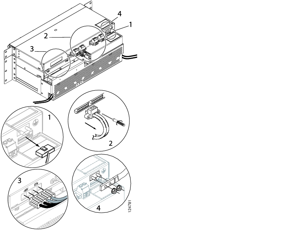
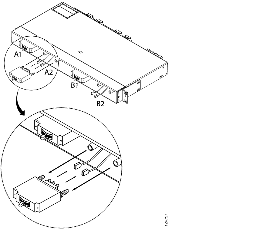
Figure 3-1 Removing the 1 RU DC Cable

Step 5 Locate the distribution alarm cable at the rear of the 1RU DC Distribution Shelf.

Step 6 Remove the 10 pin Molex™ alarm cable by squeezing the top and pulling the cable away from the shelf ( Figure 3-1 #1).

Step 7 Locate the four 6AWG (16mmІ) power cables provided at the rear of the 1RU Distribution Shelf.

Step 8 Remove the power cables by pulling them out and away from the 1RU Distribution Shelf ( Figure 3-1 #3).


Note Cover the connectors to insulate the live current on the lugs.


Step 9 Locate the ground cable attached to the #10 studs at the rear of the 1RU Distribution Shelf.

Step 10 Using an 8mm socket or wrench remove the nuts and the ground cable ( Figure 3-1 #4).

Step 11 Remove the four screws that mount the shelf to the cabinet/rack ( Figure 3-2).

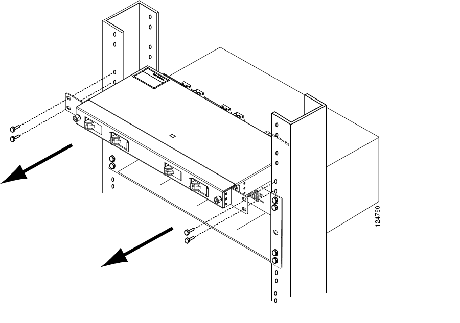
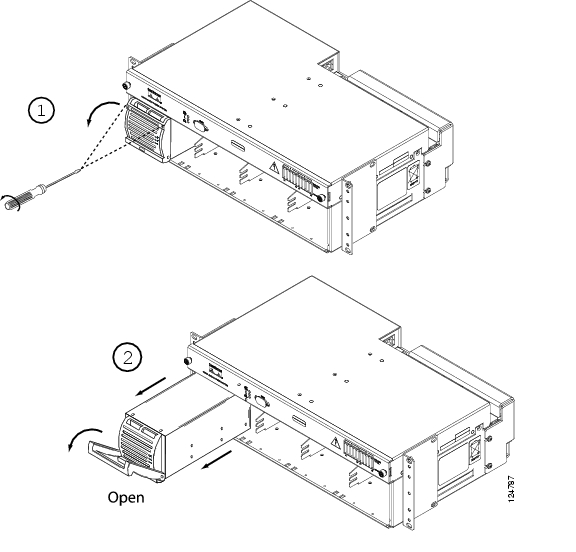
Figure 3-2 Removing the 1 RU Distribution Shelf

Step 12 Slide the 1RU Distribution Shelf away from the cabinet/rack.

Step 13 To reinstall a replacement 1RU Distribution Shelf, comlete the "2.2.2  Install the 1 RU Distribution Shelf" procedure on page 2-6.


3.2.2  Replace the Controller Tray


Step 1 Locate the controller faceplate on the system shelf.

Step 2 Remove the controller faceplate by loosening the two front thumbscrews to access the sliding controller tray ( Figure 3-3).

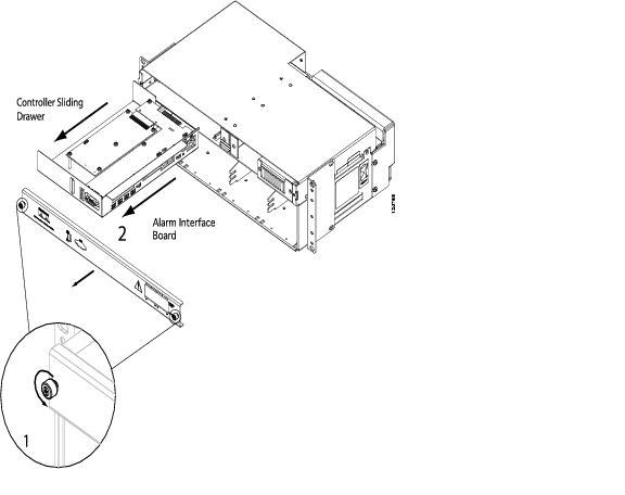
Figure 3-3 Removing the Controller Faceplate

Step 3 Slide the controller tray out and away from the system shelf to access the Alarm Interface Board ( Figure 3-3 #2).

Step 4 Remove the Alarm Interface Board DC terminal block ( Figure 3-4 or Figure 3-5 #1, depending on your controller hardware).

Step 5 Remove the alarm cable connections ( Figure 3-4 or Figure 3-5 #2). If alarm cables are not labeled with the jumper number, label the cables with the appropriate jumper number: J16, J15, J14 (1,2,3), and J14 (4,5,6)/J13 (for the system without an LCD).

-J16 terminal block

-J15 terminal block

-J14/J13 terminal blocks

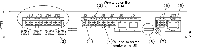
Figure 3-4 Removing the Alarm Interface Board Cable on the Version 1 of the Controller Hardware

Figure 3-5 Removing the Alarm Interface Board Cable on the Version 2 of the Controller Hardware

Step 6 Remove the intra-shelf communications cabling:

J9 terminal block ( Figure 3-4 or Figure 3-5 #3)

J8 terminal block ( Figure 3-4 or Figure 3-5 #4)

J1 Ethernet cable ( Figure 3-4 or Figure 3-5 #5)

J1 terminal block ( Figure 3-4 or Figure 3-5 #6)

Step 7 Remove the controller tray ground connection by removing the Phillips screw ( Figure 3-4 or Figure 3-5 #7).

Step 8 Remove the wire tie holding the controller tray in the system shelf ( Figure 3-4 or Figure 3-5 #8).

Step 9 Pull the controller tray out of the system shelf.

Step 10 Install the replacement controller tray by placing it in the system shelf.

Step 11 Reinstall the controller tray ground connection by connecting the Phillips screw ( Figure 3-4 or Figure 3-5 #7).

Step 12 Use a new wire tie to replace the one that was removed in Step 8.

Step 13 Reconnect the intra-shelf communications cabling (cables are labeled with the appropriate jumper number):

J9 terminal block ( Figure 3-4 or Figure 3-5 #3)

J8 terminal block ( Figure 3-4 or Figure 3-5 #4)

J1 Ethernet cable ( Figure 3-4 or Figure 3-5 #5)

J1 terminal block ( Figure 3-4 or Figure 3-5 #6)

Step 14 Reconnect the alarm cable connections ( Figure 3-4 or Figure 3-5 #2).

-J16 terminal block

-J15 terminal block

-J14/J13 terminal blocks

Step 15 Slide the controller tray back into the system shelf.

Step 16 Replace the controller faceplate by attaching it to the system shelf with the two front thumbscrews.

Step 17 After installing the controller, the controller and rectifier LEDs will blink. It may take a few minutes for the controller to communicate with all rectifiers. At this point, all rectifier output voltages will return to the programmed level. During this syncronization period output will not be affected.


3.2.3  Replace Circuit Breakers


Step 1 Make certain all breakers to be replaced are in the OFF position ( Figure 3-6).

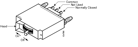
Figure 3-6 Circuit Breaker On/Off Positions

Step 2 Remove the 1RU Distribution Shelf faceplate by loosening the two thumbscrews on the shelf faceplate ( Figure 3-7).

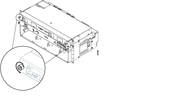
Figure 3-7 Removing the 1 RU Distribution Shelf Faceplate

Step 3 Locate the breaker that is to be removed.

Step 4 Grasp the breaker firmly at the front and pull out until the quick disconnects disengage from their mounts.

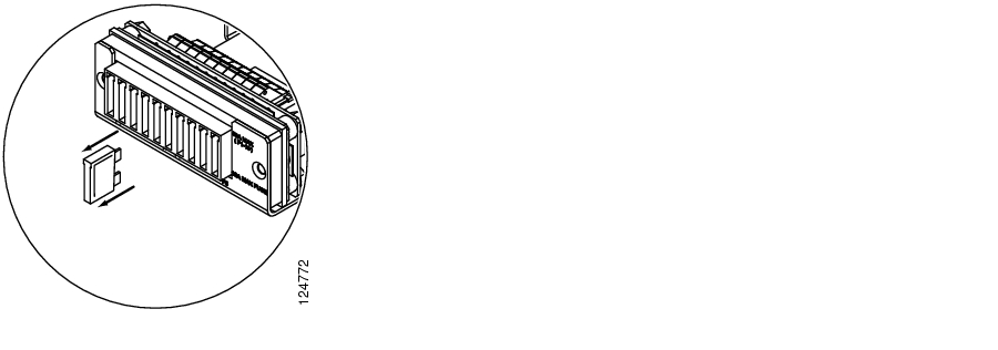
Figure 3-8 Removing a Circuit Breaker

Step 5 Remove the alarm cable connections from the rear of the breaker ( Figure 3-8).

Step 6 Pull the breaker straight out from the 1RU Distribution Shelf.

Step 7 To reinstall a replacement 1RU Distribution Shelf see the "2.2.2  Install the 1 RU Distribution Shelf" procedure on page 2-6.


3.2.4  Replace a Rectifier


Note For more information on uninstalling a rectifier, see the "Remove Modules" section.


Step 1 Locate the rectifier that is to be removed.

Step 2 Loosen the mounting screws to allow the rectifier handle to open ( Figure 3-9 #1).

Step 3 Grasp the top of the handle and pull down until the handle locks into the open position ( Figure 3-9 #2).

Figure 3-9 Removing a Rectifier

Step 4 Grasp the handle and gently pull the module out and away from the shelf.


Caution The rectifier module may be hot when being pulled from the shelf. To avoid personal injury, wait until the rectifier has cooled before removing from the system shelf.

Step 5 Continue to pull the rectifier until it is halfway out of the shelf. Grasp the bottom of the rectifier with one hand and continue using the other hand to pull the rectifier out.

Step 6 Pull the rectifier out of the shelf. The system will generate a communication error, which will last until a new rectifier is inserted.

Step 7 For information on installing a rectifier module, see the "2.3.1  Install the Rectifiers" procedure on page 2-16.


3.2.5  Replace GMT Fuses


Step 1 Locate the GMT fuse that is to be removed.

Step 2 Grasp the fuse firmly at the front and pull out ( Figure 3-10).

Figure 3-10 Removing a GMT Fuse

Step 3 For information on installing GMT fuses, see the "2.5.1  Install GMT Fuse Connections" procedure on page 2-25.


Caution When replacing GMT fuses, always use the same size fuse unless the GMT fuse output cabling is upgraded as well. For more information on the appropriate cable/fuse sizes, see Table 1-2 on page 1-6.


hometocprevnextglossaryfeedbacksearchhelp

Posted: Fri Jun 16 19:19:27 PDT 2006
All contents are Copyright © 1992--2006 Cisco Systems, Inc. All rights reserved.
Important Notices and Privacy Statement.