|
|

Table Of Contents
2.1.3 Installation and Commissioning Checklist
2.2 Install AC/DC Power System Components
2.2.1 Install the System Shelf
2.2.2 Install the 1 RU Distribution Shelf
2.2.3 Install the Ground Cable
2.5 Install Load-and-Return Connections
2.5.1 Install GMT Fuse Connections
2.5.2 Install 1 RU Distribution Shelf Load Connections
2.6.2 Small to Medium System Upgrade
2.6.3 Medium to Large System Upgrade
2.6.4 Small to Large System Upgrade
System Installation
This provides step-by-step instructions for installing a Cisco AC/DC Power System. If you are installing a new system, begin with the "Pre-Installation" section. If you are upgrading an existing system, go to the "System Upgrades" section for instructions.
2.1 Pre-Installation
The following information should be reviewed before attempting to install the Cisco AC/DC Power System.This section includes shelf markings, tools, equipment, and an installation checklist. Refer to the "1.2 Safety Recommendations" section on page 1-8 before beginning installation.
Note
Each system installation is unique, so please review specific site requirements and system configurations before installing the system.
2.1.1 Ground Symbol
Figure 2-1 shows the ground symbol located on the Cisco AC/DC Power System.
Figure 2-1 Ground Symbol
2.1.2 Tools Required
The following tools and parts are required for safe installation of the Cisco AC/DC Power System:
•
•
•
•
1
2.1.3 Installation and Commissioning Checklist
•
•
•
•
•
•
•
•
•
•
2.1.4 Installation Materials
Table 2-1 and Table 2-2 list the Cisco supplied installation materials that ship with the Cisco AC/DC Power System. Table 2-3 lists materials that will need to be furnished at the install location.
2.2 Install AC/DC Power System Components
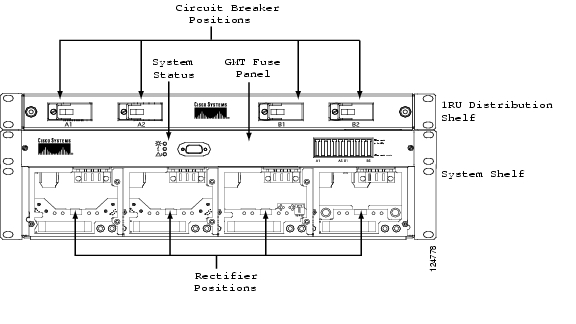
The following sections contain instructions for installing components. Figure 2-2 shows a drawing of the Cisco AC/DC Power System without rectifiers.
Figure 2-2 Cisco AC/DC Power System Front View
2.2.1 Install the System Shelf
The system shelf should be installed first, followed by the 1 RU Distribution Shelf (if this option is included as part of the installation).
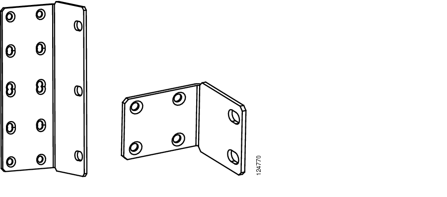
Step 1
Figure 2-3 ETSI Shelf Ear Mounts (system shelf and 1RU Distribution Shelf)
Step 2
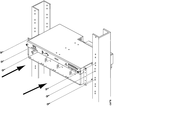
Step 3
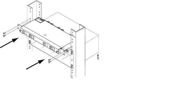
Figure 2-4 Installing the System Shelf
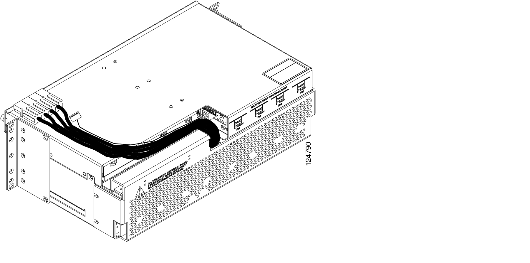
Step 4
Figure 2-5 1 RU Distribution Cable Dressing
2.2.2 Install the 1 RU Distribution Shelf
Systems equipped with an optional 1 RU Distribution Shelf require power connections from the system shelf to the 1 RU Distribution Shelf using four cables terminated with Anderson power pole connectors. These cable connectors are pre-wired to the system shelf and should be connected to the 1 RU Distribution Shelf during installation.
Note
In addition, the distribution alarm connection is made via a pre-wired 10 pin Molex™ connector from the system shelf and should be connected to the 1 RU Distribution Shelf at the indicated connection point.
Step 1
Step 2
Step 3
Step 4
Figure 2-6 1 RU Distribution Shelf Installation
2.2.2.1 Install the Communications Cabling (Optional)
If the power system is equipped with the 1 RU Distribution Shelf, follow the instructions below. For power systems without the 1 RU Distribution Shelf, skip this procedure and go to the "Install the Ground Cable" procedure.
Intra-system shelf communication is accomplished using a 10 pin Molex™ connector originating from the system shelf and connecting to the 1 RU Distribution Shelf. Use the following instructions to install the communications cabling:
Step 1
Step 2
Note
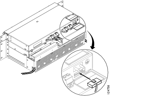
Figure 2-7 1 RU Distribution Shelf Alarm Cabling
2.2.2.2 Install the DC Power Cabling (Optional)
If the system is equipped with the 1 RU Distribution Shelf, follow the instructions below. For systems without the 1 RU Distribution Shelf, skip this procedure and go to the "Install the Ground Cable" procedure.
Step 1
Step 2
Note
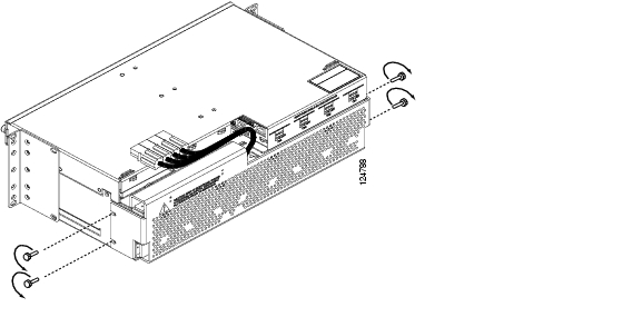
Figure 2-8 Installing 1 RU DC Cabling
2.2.3 Install the Ground Cable
Warning
The equipment rack/cabinet, system, and optional distribution shelf need to be properly grounded to ensure the safe and efficient operation of the Cisco AC/DC Power System. Refer to NEC, CEC, ANSI T1-333, ETSI 300-386-TC, and local codes for guidelines on bonding telecom DC power equipment to building ground.
The system shelf should be connected to the rack/cabinet frame by a UL-listed 6 AWG (16mm≤) wire with an insulation rating of at least 75Α Celsius. Two #10 studs are provided at the rear of the shelf. The connection at the shelf end is made using a UL-listed double-hole lug 1/4in and 5/8in. center-to-center (lug part # Panduit LCD6-14A-L or equivalent).
The optional 1 RU Distribution Shelf should be bonded to the frame by a UL-listed 6 AWG (16mm≤) wire with an insulation rating of at least 75Α Celsius. Two #10 studs are provided at the rear of the shelf for this purpose. The connection at the shelf end is made using a UL-listed double-hole lug 1/4in. and 5/8in. center-to-center (lug part # Panduit LCD6-14A-L or equivalent).
2.2.3.1 Install the Cabinet/Rack Ground
The equipment rack should be bonded to the building principal ground busbar. Refer to the NEC, CEC, ANSI T1-333, ETSI 300-386-TC, and local codes for guidelines on bonding telecom DC power equipment to the building ground.
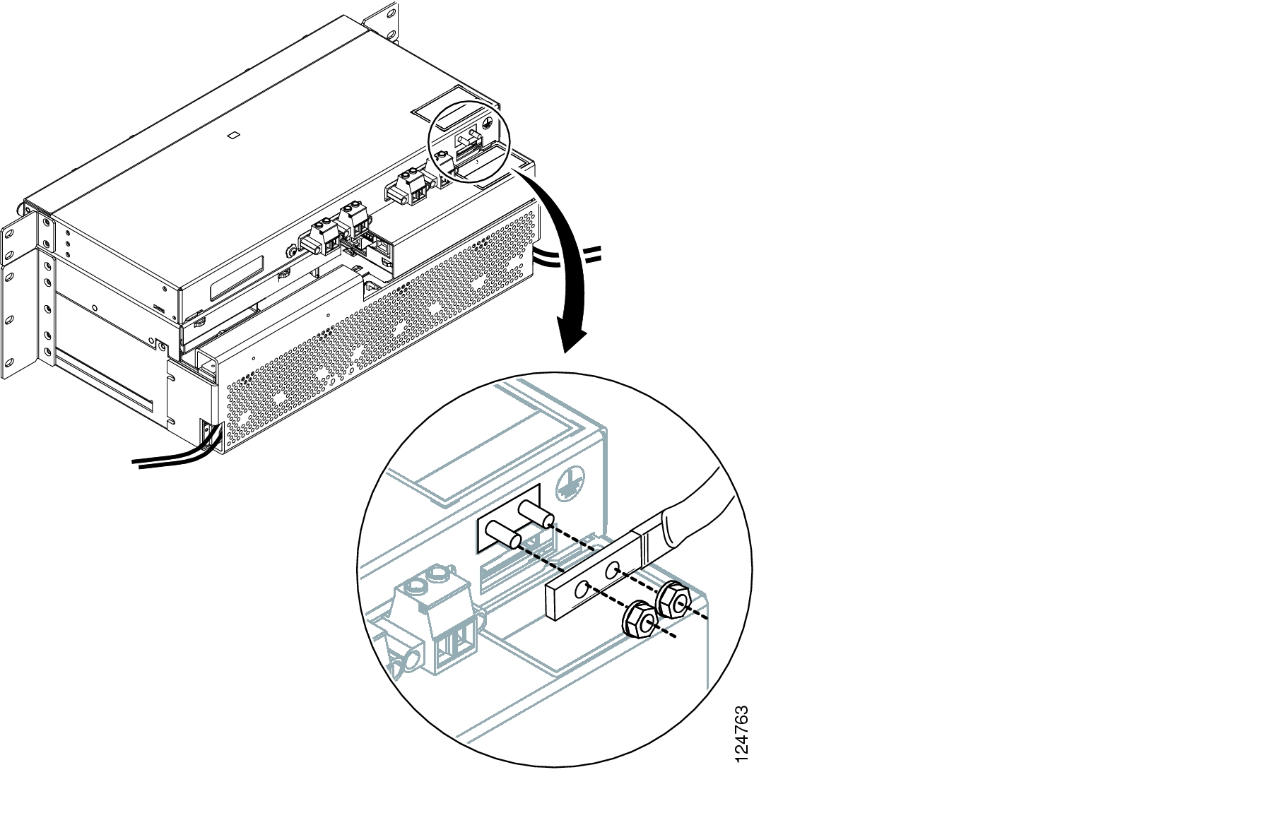
2.2.3.2 Install the System Shelf Ground
Step 1
Figure 2-9 Removing the System Shelf Rear Cover
Step 2
Step 3
Step 4
Figure 2-10 Installing the System Shelf Ground
Step 5
2.2.3.3 Install the 1 RU Distribution Shelf Ground
Step 1
Step 2
Step 3
Step 4
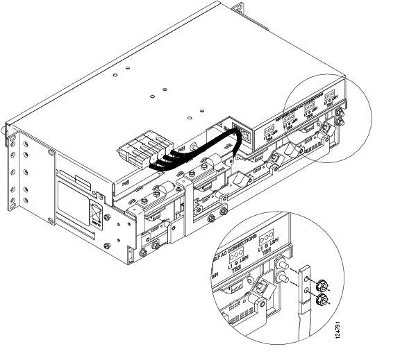
Figure 2-11 Installing the 1 RU Distribution Shelf Ground
2.3 Install AC Power Cables
Each rectifier in the system shelf is individually powered through a 110/230 V AC single phase 15A circuit and draws a maximum of 9.1A.
Each rectifier position in the shelf can be powered by either:
•
•
•
•
Note
•
•
–
–
–
–
–
Warning
•
To install AC power to the Cisco AC/DC Power System:
Step 1
Step 2
Step 3
Note
Step 4
Step 5
Step 6
Figure 2-12 Installing the AC Cable Shelf
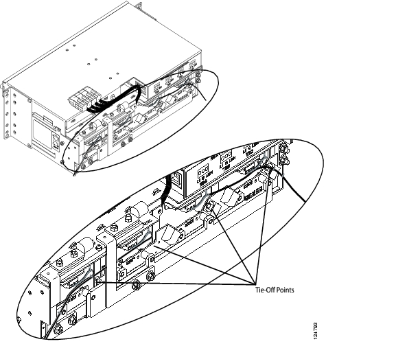
Step 7
Figure 2-13 Routing AC Cables
Step 8
Step 9
Step 10
Step 11
Note
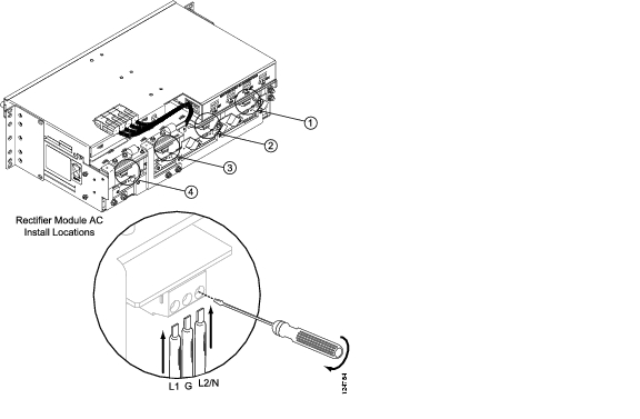
2.3.1 Install the Rectifiers
To install the rectifiers in the Cisco AC/DC Power System:
Step 1
Step 2
Step 3
Step 4
Step 5
Figure 2-14 Installing a Rectifier
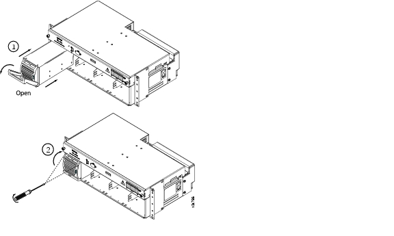
Step 6
Step 7
Figure 2-15 Removing a Rectifier Blank Faceplate
Step 8
For more information on installing rectifiers in a powered system, see the "Add Modules" section.
2.4 Install Circuit Breakers
Note
Large systems equipped with the 1 RU Distribution Shelf require the installation of circuit breakers to ensure proper system protection (the 1 RU Distribution Shelf is shipped with circuit breakers installed for use in medium systems). To install circuit breakers in a large system:
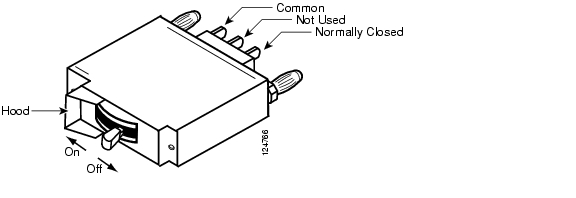
Step 1
Figure 2-16 Circuit Breaker On/Off Positions
Step 2
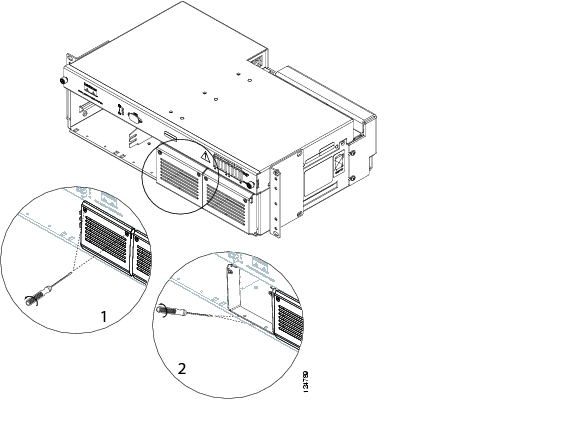
Figure 2-17 Removing the 1 RU Distribution Shelf Faceplate
Step 3
Step 4
Table 2-5 Circuit Breaker Positions
Small
n/a
n/a
n/a
n/a
Medium
X
X
Large
X
X
X
X
1 Future Upgrade
2 Future Upgrade
Step 5
Figure 2-18 Installing a Circuit Breaker
Step 6
Step 7
Step 8
2.4.1 Install the Alarm Cable
The following explains how to install alarm communication cabling to the Cisco AC/DC Power System Controller.
Warning
Note
To install alarm cabling to the Cisco AC/DC Power System:
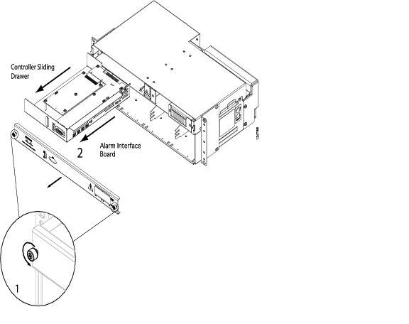
Step 1
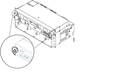
Figure 2-19 Removing the Controller Faceplate
Step 2
Step 3
Figure 2-20 Installing an Alarm Cable
Step 4
Note
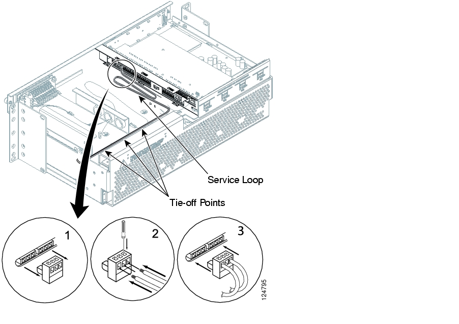
Step 5
Step 6
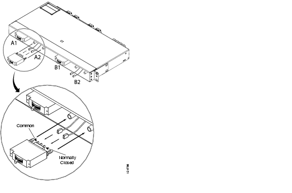
Figure 2-21 Alarm Board Connection Points
Step 7
Step 8
Step 9
2.5 Install Load-and-Return Connections
The following section contains information on installing different distribution options available for the power system. Table 2-7 provides a list of recommended wire gauges for both the GMT fuse panel and the 1 RU Distribution Shelf.
2.5.1 Install GMT Fuse Connections
Load connections to the GMT fuse panel are made using spring loaded terminals that do not require the use of connection lugs.
Step 1
Figure 2-22 GMT Drawer
Step 2
Step 3
Figure 2-23 Installing GMT Cabling
Step 4
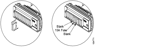
Step 5
Figure 2-24 Installing Fuses
Note
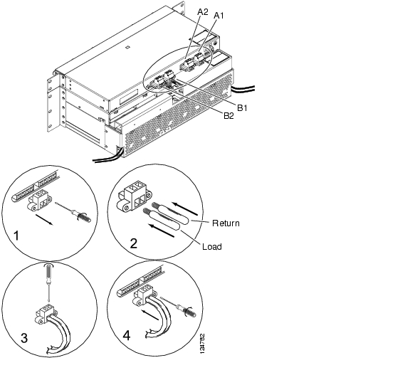
2.5.2 Install 1 RU Distribution Shelf Load Connections
The following section is for systems that use the 1 RU Distribution Shelf. For systems without the 1 RU Distribution Shelf, go to "System Operation."
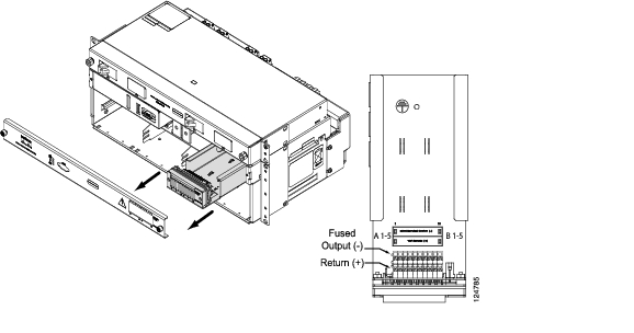
Step 1
Step 2
Step 3
Figure 2-25 Installing Load Connections
Step 4
Step 5
Step 6
Step 7
Step 8
2.6 System Upgrades
If the installation is an upgrade of a pre-existing system, the following sections give a list of the procedures needed to upgrade the system:
•
•
•
Review the following sections before attempting a system upgrade:
Note
2.6.1 GMT Fuses
To add fuses to the GMT fuse block, see the "Install GMT Fuse Connections" procedure.
2.6.2 Small to Medium System Upgrade
To upgrade a small system (2 rectifiers, no 1 RU Distribution Shelf) to a medium system (3 rectifiers, 1 RU Distribution Shelf with 2 circuit breakers), use the following sections:
•
•
•
•
•
2.6.3 Medium to Large System Upgrade
To upgrade a medium system (3 rectifiers, 1 RU Distribution Shelf with 2 circuit breakers) to a large system (4 rectifiers, 1 RU Distribution Shelf with 4 circuit breakers), use the following sections:
•
2.6.4 Small to Large System Upgrade
To upgrade a small system (2 rectifiers, no 1 RU Distribution Shelf) to a large system (4 rectifiers, 1 RU Distribution Shelf with 4 circuit breakers), use the following sections:
•
•
![]()
![]()
![]()
![]()
![]()
![]()
![]()
![]()
Posted: Mon May 22 11:10:45 PDT 2006
All contents are Copyright © 1992--2006 Cisco Systems, Inc. All rights reserved.
Important Notices and Privacy Statement.