cc/td/doc/product/ong/acdcpwr/acdcpr10
hometocprevnextglossaryfeedbacksearchhelp
PDF

Table Of Contents

Introduction

1.1  System Description

1.1.1  System Shelf

1.1.2  Rectifier Modules

1.1.3  GMT Fuses

1.1.4  1 RU Distribution Shelf

1.1.5  System Configurations

1.1.6  General Specifications

1.2  Safety Recommendations

1.2.1  Installation Warning

1.2.2  Operating Temperature Warnings

1.2.3  Electrical Safety Warnings


Introduction


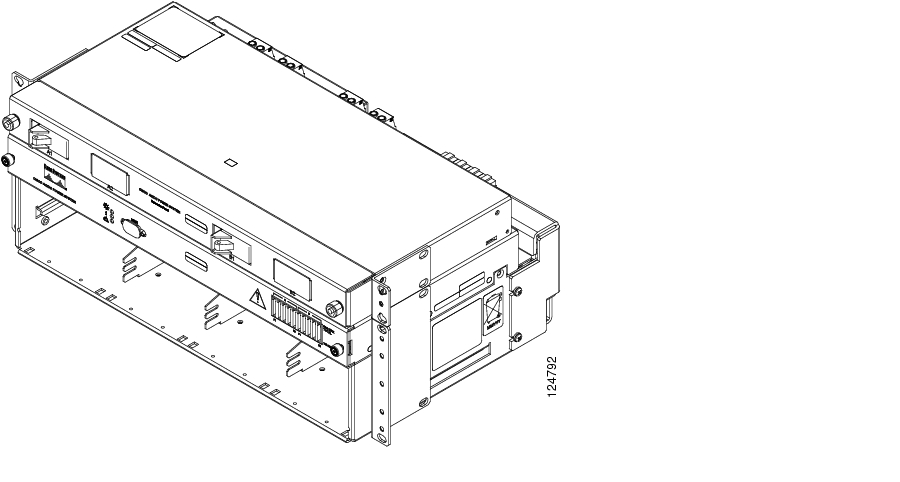
The Cisco AC/DC Power System is a rack-mounted, AC-to-DC power system that provides a scalable, compact solution for powering optical platforms at site locations with only AC power available. The system accepts AC inputs and converts them to nominal -48 VDC for DC-powered equipment. This compact system provides N+1 redundancy in rectifiers, automated alarm generation, and integrated DC power distribution through a GMT fuse panel and available four-position 1RU circuit breaker distribution shelf. This system provides nomimal -48 VDC service to DC-powered network elements (NEs) through redundant feeds, complementing the resiliency of Cisco's line of Carrier Class optical products.

The Cisco AC/DC Power System is designed to be mounted in a variety of rack types including IEC, ANSI (19 inches), ANSI (23 inches), and ETSI configurations and requires only 177.8mm (7.0in.) of vertical space for medium and large systems and 133.4mm (5.25in.) for small systems. The system is based on the CSCO-PWR-RECT rectifier module and allows three different configurations based on load requirements that range from 13.3A to 96A. Additionally, power distribution is accomplished using a GMT fuse block and/or an optional 1 RU distribution shelf (depending on system size).

The Cisco AC/DC Power System offers these features:

AC input (A) 100-120VAC

AC input (B) 200-250VAC

Nominal -48 VDC rectifier providing up to 1600W

Front access design

Temperature hardened -40ºC to +55ºC

Available in 19in. (IEC and ANSI), ETSI (21in. inside [610mm]), or 23in. mounting arrangements

Available external distribution shelf with up to 4 load circuit breakers

10 position GMT fuse panel

Active high power factor correction

90% or greater efficiency

Front panel LCD interface

1.1  System Description

This section provides descriptions of the system shelf, rectifier modules, GMT fuses, and the 1 RU distribution shelf.

1.1.1  System Shelf

The AC/DC power system shelf consists of four rectifier slots and system monitoring/control interfaces. The system controller provides rectifier monitoring, operational data collection, alarm generation, and intra-system communications regulation.

Figure 1-1 Cisco AC/DC Power System (with Optional 1RU DC Distribution Shelf)

There are two system shelves, one of which has an LCD display on the front of the shelf.

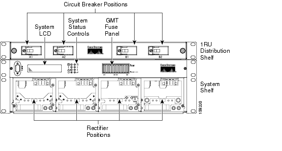
Figure 1-2 shows a front view of the version of the system shelf with the LCD screen. The optional 1 RU DC distribution shelf is also shown.

Figure 1-2 Component Locations (Front View) on the System Shelf with LCD Screen

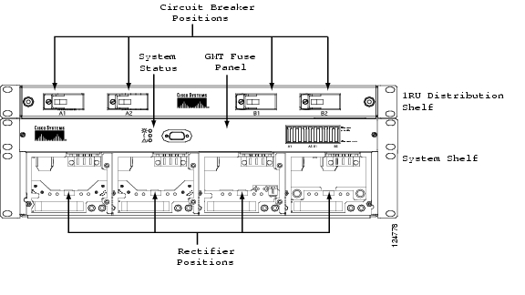
Figure 1-3 shows a front view of the version of the system shelf that does not have an LCD screen. The optional 1 RU DC distribution shelf is also shown.

Figure 1-3 Component Locations (Front View) on the System Shelf without an LCD Screen

1.1.2  Rectifier Modules

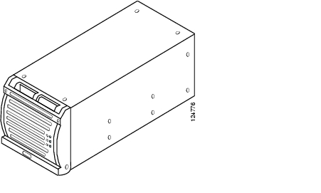
AC-to-DC power conversion is accomplished using two, three, or four hot-swappable CSCO-PWR-RECT rectifiers, each with an output voltage of nominal -48 VDC. Figure 1-4 shows a CSCO-PWR-RECT rectifier module.


Note The output voltage range is set at the factory and is not user configurable.


Figure 1-4 CSCO-PWR-RECT Rectifier Module

1.1.3  GMT Fuses

The system shelf is equipped with a 10-position GMT fuse panel. The GMT fuse panel has a 50A maximum total capacity with a maximum fuse rating of up to 15A (for up to three positions). The fuses are alarmed and are reported through the system controller.

Figure 1-5 GMT Fuse Panel

1.1.4  1 RU Distribution Shelf

The optional 1RU Distribution Shelf is installed in systems that contain more than 2 rectifiers and acts as an additional protection point for system loads. The shelf has a rating of 96A and can be equipped with up to four circuit breakers (up to a maximum rating of 30A each). The breakers are alarmed through the system controller.

Figure 1-6 1 RU Distribution Shelf

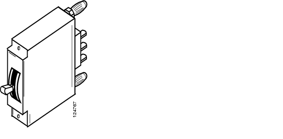
The 1RU External Distribution Shelf can accommodate up to four Series-Trip circuit breaker positions. These breakers have "bullet type" connectors for quick connect and disconnect ( Figure 1-7). Circuit breakers can be rated from 5A-30A.

Figure 1-7 Circuit Breaker

1.1.5  System Configurations

Table 1-1 lists the configurations available for the Cisco AC/DC Power System.

Table 1-1 System Configurations

Configuration
Rectifiers
Distribution
Output at 220V AC
Output at 110V AC

Small Systems

2 CSCO-PWR-RECT Modules

10-position GMT Fuse Block

32A

13.3A

Medium Systems

3 CSCO-PWR-RECT Modules

10-position GMT Fuse Block

4- position 1RU DC Distribution Shelf

64A

26.6A

Large Systems

4 CSCO-PWR-RECT Modules

10-position GMT Fuse Block

4- position 1RU DC Distribution Shelf

96A

40A


1.1.6  General Specifications

Table 1-2 provides cabling specifications for the Cisco AC/DC Power System.

Table 1-2 Cabling Specifications

From
To
Wire Gauge
Ampacity

System Shelf

1U DC Distribution Shelf

4 x 6AWG (16mm²)

(intra-shelf cabling)

96A (max)

Circuit Breakers

Load

10 - 8AWG

(6mm² - 10mm²)

30A (max)

GMT Fuse Block

Load

16 - 14AWG

(1.5mm² - 2.5mm²)

15A (max)

AC Service Panel

System Shelf

3 conductor 14AWG (2.5mm²) per AC input

9.1A x (4) inputs

<37A Total


Table 1-3 provides electrical specifications for the Cisco AD/DC Power System.

Table 1-3 Electrical Specifications

Electrical
Value

Input Voltage

(A) 100-120VAC
(B) 200-250VAC

Input Frequency

44-66 Hz.

Transient Response

+/- 4%, recovery time 2ms

Load Sharing

+/- 5% of nominal current


Table 1-4 provides protection specifications for the Cisco AC/DC Power System.

Table 1-4 Protection Specifications

Protection
Description

Overcurrent (output)

Short circuit and automatic current limiting

Overvoltage

Selective shutdown of modules at excessive output voltages


Table 1-5 provides status and alarm specifications for the Cisco AC/DC Power System.

Table 1-5 Status and Alarm Specifications

Status & Alarms
Description

Alarm Contacts

Four form-C alarm contacts (Low Voltage, Mains Error, Module Failure, Fuse/Circuit Breaker Failure), maximum 60 VDC, rated at 1A

Status (Rectifier)

Green LED indicates power is within acceptable range

Yellow LED indicates current limit/thermal protection

Red LED indicates overvoltage shutdown or rectifier alarm


Table 1-6 provides mechanical specifications of the Cisco AC/DC Power System.

Table 1-6 Mechanical Specifications

Mechanical
Description

Shelf Dimensions WxHxD

17.4 x 5.25 x 10.8in. (442 x 132.9 x274mm)

1RU Shelf WxHxD

17.1 x 1.69 x 9.175in. (434 x 43 x 233mm)

Mounting

ETSI, 19in. (IEC and ANSI) or 23in.


Table 1-7 provides environmental specifications for the Cisco AC/DC Power System.

Table 1-7 Environmental Specifications

Environment
Description

Shock/Vibration

(NEBS) Level 3, Class B Certification

Earthquake

Zone 4 Compliant

Audible Noise

<60 dBA

Ambient Temperature

-40°C to 55°C

Storage Temperature

-40°C to +85°C

Relative Humidity

10-90%, non-condensing


Table 1-8 provides compliance specifications for the Cisco AC/DC Power System.

Table 1-8 Compliance Specifications 

Compliance
Description

Radiated EMC

EN 61000-6-2, EN 61000-6-3, FCC Part 15 Class B

EMC

EN 61000-6-2, EN 61000-6-4

Safety

CSA C22-2 No. 60950-1, UL 60950-1 and IEC60950-1/EN60950-1

ESD Immunity

EN61000-4-2

RF Immunity

EN61000-4-3

Surge Immunity

IEC/EN61000-4-5

Fast Transient/Burst Immunity

IEC/EN61000-4-4

Immunity

EN61000-4-2

ETSI

300-386-TC


1

1.2  Safety Recommendations

Any device that uses electricity requires proper guidelines to ensure safety.


Warning Only trained and qualified personnel should be allowed to install, replace, or service this equipment. Statement 1030


Warning This unit is intended for installation in restricted access areas. A restricted access area can be accessed only through the use of a special tool, lock and key, or other means of security. Statement 1017


The Cisco AC/DC Power System should only be installed or serviced by qualified personnel.

An ESD wrist strap is included to protect sensitive electronics and should be connected to a metal surface to act as a ground. This ensures that all components have the same charge. An ESD wrist strap should be used when working with internal components that are installed in the shelf. The wrist strap connects at the rear of the system shelf as shown in Figure 1-8. If rear access is not available, the ESD wrist strap can be connected to the shelf mounting ears or the controller faceplate thumbscrews.

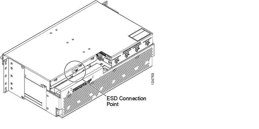
Figure 1-8 ESD Wrist Strap Connection Point

Keep the system area clear and dust-free during and after the installation.

Always check for possible hazards before beginning work.

This equipment is designed to permit the connection of a grounded conductor for the DC supply circuit at the equipment.

1.2.1  Installation Warning

The following safety guidelines should be observed when transporting or moving the system to the install location:

Before moving the Cisco AC/DC Power System, read the system specifications sheet to determine if the site meets all the size, environmental, and power requirements.

The Cisco AC/DC Power System should be properly mounted to the equipment rack.

The Cisco AC/DC Power System is designed for installation in restricted access locations. A restricted access location is defined as an equipment location where both of the following conditions apply:

Access can only be gained by service persons or users who understand the restrictions applied to the location and any precautions that must be taken.

Access to the system is obtained through the use of a tool or lock and key, or other means of security, and is controlled by the authority responsible for the location.

1.2.2  Operating Temperature Warnings


Warning To prevent the system from overheating, do not operate it in an area that exceeds the maximum recommended ambient temperature of: 55° Celsius.
Statement 1047


Warning To prevent airflow restriction, allow clearance around the ventilation openings to be at least 2.0 inches (50.8 mm).


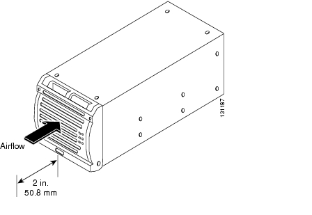
Figure 1-9 Two-Inch Clearance Around Front Ventilation Opening

This power system is intended for use in a restricted location where the ambient temperature falls between -40° and +55° Celsius. It is not recommended to continually operate the power system in an area that exceeds the maximum recommended operating temperature. To prevent the Cisco AC/DC Power System from overheating, the rectifier automatically shuts down when a thermal alarm is tripped.

1.2.3  Electrical Safety Warnings

The following are electrical safety recommendations for working near the Cisco AC/DC Power System:


Warning Before working on equipment that is connected to power lines, remove jewelry (including rings, necklaces, and watches). Metal objects will heat up when connected to power and ground and can cause serious burns or weld the metal object to the terminals. Statement 43


Warning This equipment must be grounded. Never defeat the ground conductor or operate the equipment in the absence of a suitably installed ground conductor. Contact the appropriate electrical inspection authority or an electrician if you are uncertain that suitable grounding is available. Statement 1024


Warning Installation of the equipment must comply with local and national electrical codes. Statement 1074


Warning Before working on a chassis or working near power supplies, unplug the power cord on AC units; disconnect the power at the circuit breaker on DC units. Statement 12


Warning This product requires short-circuit (overcurrent) protection, to be provided as part of the building installation. Install only in accordance with national and local wiring regulations. Statement 1045


Warning Installation of the equipment must comply with local and national electrical codes. Statement 1074


Before connecting the AC input source to the power system, always verify frequency and voltage.

When making AC connections, all AC power and DC load distribution breakers should be in the OFF position.

Ensure that the proper size circuit protection is being used.


hometocprevnextglossaryfeedbacksearchhelp

Posted: Fri Jun 16 19:17:00 PDT 2006
All contents are Copyright © 1992--2006 Cisco Systems, Inc. All rights reserved.
Important Notices and Privacy Statement.