|
|

Table Of Contents
4.2.1 Alarm Interface Board and Connections
4.2.2 Basic Controller Functions
System Operation
4.1 System Commissioning
The following section should be used to power-up the system for the first time.
Step 1
Turn on AC breakers at the AC distribution panel to power up the shelf through the rectifiers.
Step 2
Step 3
4.2 General Information
The Power Control System (XCS) ( Figure 4-1) is a supervisory system that is designed to control AC/DC power systems that are based on XR1648 rectifier modules.
Communication is accomplished through an alarm interface board and a backplane that connects to the rectifier modules.
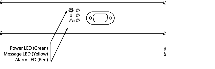
Figure 4-1 System Control Unit
4.2.1 Alarm Interface Board and Connections
The alarm interface board is the main connection point for external communication inputs. The board is located inside the controller and can be accessed by removing the front controller cover and then sliding out the controller tray to expose the alarm connections (located on the right-hand side).
Alarm connections are made at the terminal block located on the Alarm/Interface PC board. The green connectors can be easily removed for ease in installing the wires into the connector; 22 AWG (0.34mm≤) wire is recommended for connecting alarms to the alarm output terminals ( Figure 2-21 on page 2-24). External connections are Form C relay which can be monitored either Normally Closed or Normally Open. The four alarms are numbered 1 through 4. (Refer to Table 2-6 on page 2-23).
Note
The following is a list of alarm board connections including descriptions and cabling:
•
•
•
4.2.2 Basic Controller Functions
The following section contains basic controller functions including starting the controller, adding modules, and removing modules from the system.
4.2.2.1 Start the Controller
When power is applied to the controller:
Step 1
Step 2
4.2.2.2 Add Modules
When a rectifier is added to the system it will remain off until the controller detects it.
Step 1
Step 2
Step 3
Step 4
Step 5
4.2.2.3 Remove Modules
Physically removing a module from the system creates a communication error indicated by the yellow LED on the controller. The yellow LED will remain on until a rectifier is installed.
![]()
![]()
![]()
![]()
![]()
![]()
![]()
![]()
Posted: Fri Jun 16 19:16:25 PDT 2006
All contents are Copyright © 1992--2006 Cisco Systems, Inc. All rights reserved.
Important Notices and Privacy Statement.