This chapter provides procedures for changing the default transmission parameters and performance monitoring (PM) thresholds for Cisco ONS 15454 SDH electrical and optical cards. The chapter also provides procedures for converting the E1-N-14 and DS3i-N-12 cards from 1:1 to 1:N protection (E3-12 only supports 1:1 protection).
Because much of the electrical and optical card provisioning involves PM thresholds, refer to the Cisco ONS 15454 SDH Troubleshooting and Maintenance Guide for definitions and general information about ONS 15454 SDH performance monitoring parameters. In addition, refer to the ITU-T G.707, G.783, and G.841 documents. The default thresholds delivered with ONS 15454 SDH cards are based on specifications contained in those documents.
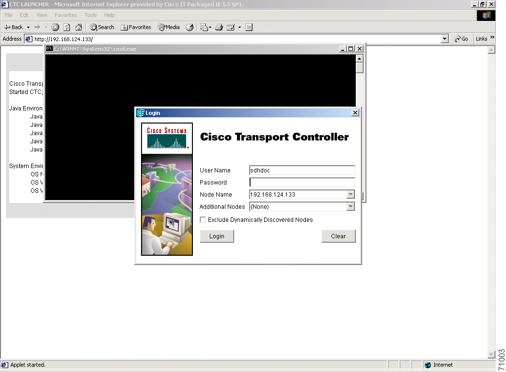
Note You start Cisco Transport Controller (CTC) using your web browser and typing the IP address of the
ONS15454 SDH shelf to be controlled into the address bar. You have to use a login with Provisioning
or Superuser authority. Starting the CTC can take a few minutes depending on the speed of your IP
connection to the ONS15454 SDH shelf. After having typed the IP address into the address bar, CTC
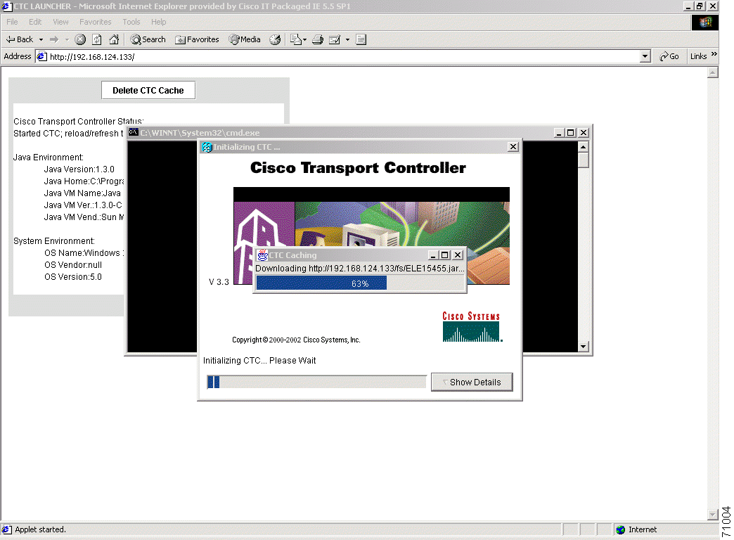
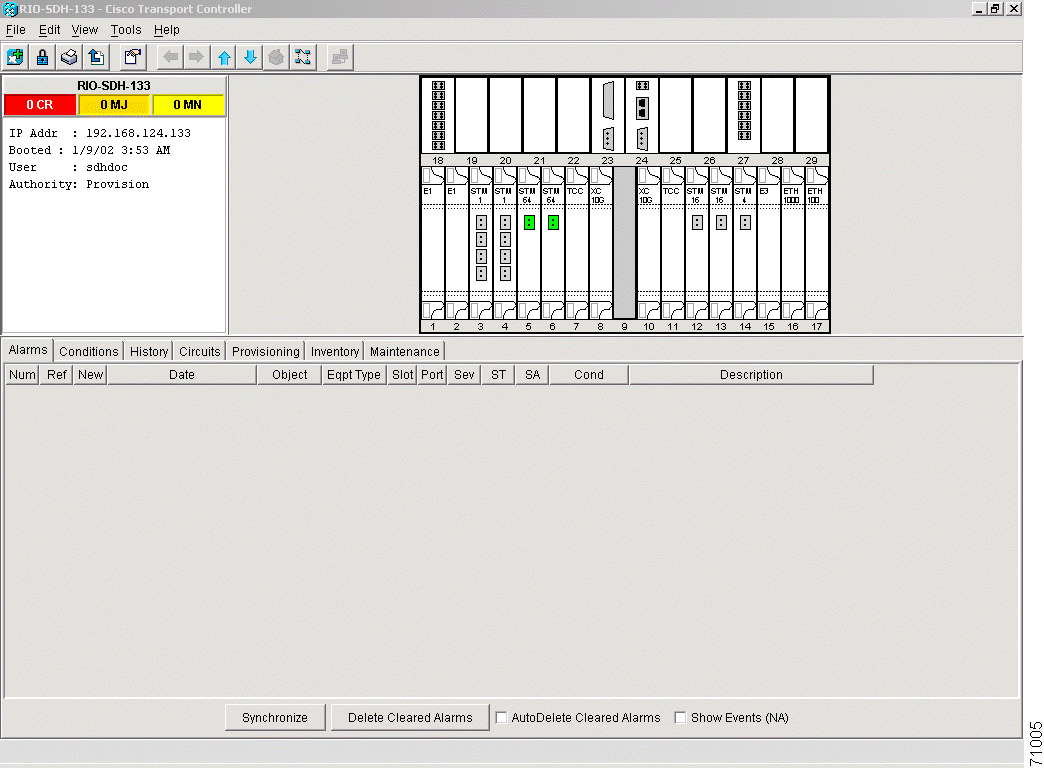
will start with screens like the ones as shown in
Figure 7-1,
Figure 7-2, and
Figure 7-3.
Figure 7-1 CTC login prompt
Figure 7-2 Reaction of the web browser after login
Downloading CTC from the ONS15454 SDH node can take up to a few minutes, depending on the speed of the web connection to the node to be controlled.
Figure 7-3 Node view of the ONS 15454 SDH node
7.1 Front Mount Electrical Connection (FMEC) Cards
The ONS 15454 SDH Front Mount Electrical Connection (FMEC) cards are only feedthrough cards to enable front access for the interfaces. They do not require any parameters to be set during provisioning. The only internal data that these cards have is inventory data.
The FMEC cards are:
FMEC-E1
FMEC-E3/DS3
FMEC-DS1/E1
MIC-A/P
MIC-C/T/P
7.2 Provisioning Electrical Cards
The ONS 15454 SDH electrical cards are pre-provisioned with settings that you can modify to manage transmission quality.
The electrical cards are:
E1-N-14
E3-12
DS3i-N-12
When you open a card in CTC (which means double-click on this card) and choose the Provisioning tab, the following subtabs are commonly displayed:
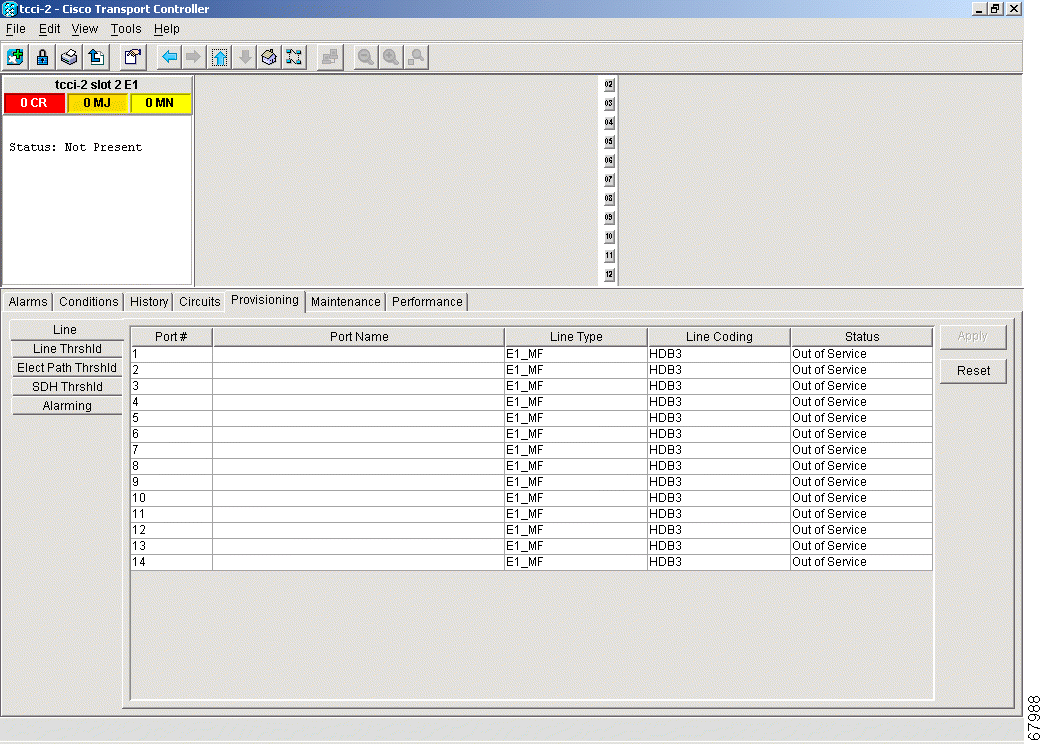
Line—Sets line setup parameters, such as line type, line coding, and line length. This is also where you put ports in and out of service.
Line Thrshld—Sets the line-level PM thresholds.
Elect Path Thrshld—Sets the path-level PM thresholds for electrical (E1, E3, DS3) traffic.
SDH Thrshld—Sets the path-level PM thresholds for SDH traffic.
Alarming—Sets alarm profiles for individual ports. See "Alarm Monitoring and Management." for information about creating alarm profiles.
As an example, Figure 7-4 shows the screen with the choices for an E1-N-14 card.
Figure 7-4 Provisioning line parameters on the E1-N-14 card
Table 7-2 provides an overview of E1-N-14, E3-12, and DS3i-N-12 parameters (an X means the item is available for the card).
Table 7-2 E1, E3, and DS-3 Card Provisioning Overview
Provisioning Item
E1-N-14
E3-12
DS3i-N-12
Line Subtab
Port #
X
X
X
Port Name
X
X
X
Line Type
X
X
Detected Line Type
X
Line Coding
X
X
Line Length
X
X
X
Status
X
X
X
Line Thrshld Subtab
Port
X
X
X
CV
X
X
X
ES
X
X
X
SES
X
X
X
LOSS
X
X
Elect Path Thrshld Subtab
Port
X
X
X
CVP
X
EB
X
BBE
X
ES
X
X
ESP
X
SES
X
X
SESP
X
SAS
X
SASP
X
UAS
X
X
UASP
X
SDH Threshold Subtab
Port
X
X
X
CV
ES
X
X
X
FC
X
SES
X
X
X
EB
X
X
X
UAS
X
X
X
BBE
X
X
X
Alarming
Port
X
X
X
Profile
X
X
X
Suppress Alarms
X
X
X
7.2.1 E1-N-14 Card Parameters
Purpose
Set the E1 (2048 kBits/s) interface parameters for required connection
Tools/Equipment
Computer with CTC
Prerequisite procedures
All shelf and card installation procedures
Required/As Needed
Required
Onsite/Remote
Onsite or remote
The ONS 15454 SDH E-1 cards (E1-N-14) provide fourteen E-1 ports. Each port operates at 2.048 MBits/s (Mbps). Default thresholds are based on recommendations in ITU-T G.841.
Procedure: Modify Line and Threshold Settings for the E-1 Card
Step 3 Depending on the setting you need to modify, click the Line, Line Thrshld, Elect Path Thrshld, SDH Thrshld, or Alarming tabs.
Step 4 Modify the settings shown in Table 7-3. For drop-down lists, choose an item from the list. For numerics, double-click the field and type the new number.
Step 5 Click Apply.
Step 6 Repeat Steps 4 - 5 for each subtab that has parameters you want to provision.
Table 7-3 E1-N-14 Card Parameters
Parameter
Description
Options
Line (Line tabs)
Port #
Port number
1 - 14
Port
Port name
To enter a name for the port, click the cell and type the name. To change a name, double-click the cell, then edit the text.
Set the E3 (34.368 MBits/s) interface parameters for required connection
Tools/Equipment
Computer with CTC
Prerequisite procedures
All shelf and card installation procedures
Required/As Needed
Required
Onsite/Remote
Onsite or remote
The ONS 15454 SDH E3-12 cards provides twelve E3 ports. Each port operates at 34.368 MBits/s (Mbps). Default thresholds are based on recommendations in ITU-T G.841.
Procedure: Modify Line and Threshold Settings for the E3-12 Card
Step 1 Display the E3-12 in CTC card view.
Step 2 Click the Provisioning tab.
Step 3 Depending on the setting you need to modify, click the Line, Line Thrshld, or SDH Thrshld subtab.
Step 4 Modify the settings shown in Table 7-4. For drop-down lists, select an item from the list. For numerics, double-click the field and type the new number.
Step 5 Click Apply.
Step 6 Repeat Steps 4 - 5 for each subtab that has parameters you want to provision.
Table 7-4 E3-12 Card Parameters
Parameter
Description
Options
Line (Line subtab)
Port #
Port number
1 - 12
Port
Port name
To enter a name for the port, click the cell and type the name. To change a name, double-click the cell, then edit the text.
Status
Places port in or out of service
Out of Service (default)
In Service
Line Thresholds (Line Thrshld subtab)
Port #
Port number
1 - 12
CV
Coding violations
Numeric. Default:
387 (15 minutes)
3865 (1 day)
ES
Errored seconds
Numeric. Default:
25 (15 minutes)
250 (1 day)
SES
Severely errored seconds
Numeric. Default:
4 (15 minutes)
40 (1 day)
LOSS
Loss of signal; number of one-second intervals containing one or more LOS defects
Set the DS3 (44.736 MBits/s) interface parameters for required connection
Tools/Equipment
Computer with CTC
Prerequisite procedures
All shelf and card installation procedures
Required/As Needed
Required
Onsite/Remote
Onsite or remote
The DS3i-N-12 cards provide twelve DS-3 ports. Each port operates at 44.736 MBits/s (Mbps). The DS3i-N-12 uses B3ZS error monitoring and enhanced performance monitoring, including P-Bit and CP-Bit monitoring. Default thresholds are based on recommendations in GR-820-CORE, Section 5.0.
Procedure: Modify Line and Threshold Settings for the DS3i-N-12 Card
Step 1 Display the DS3i-N-12 in CTC card view.
Step 2 Click the Provisioning tab.
Step 3 Depending on the setting you need to modify, click the Line, Line Thrshld, Elect Path, SDH Thrshld or Alarming subtab.
Step 4 Modify the settings shown in Table 7-5. For drop-down lists, select an item from the list. For numerics, double-click the field and type the new number.
Step 5 Click Apply.
Step 6 Repeat Steps 4 - 5 for each subtab that has parameters you want to provision.
Table 7-5 DS3i-N-12 Card Parameters
Parameter
Description
Options
Line (Line subtab)
Port #
Port number
1 - 12
Port
Port name
To enter a name for the port, click the cell and type the name. To change a name, double-click the cell, then edit the text.
Line Type
Defines the line framing type
UNFRAMED
M23
C BIT (default)
AUTO PROVISION
Detected Line Type
Displays the detected line type
Read-only
Line Coding
Defines the DS3E transmission coding type
B3ZS
Line Length
Defines the distance (in feet) from backplane connection to the next termination point
0 - 225 (default)
226 - 450
Status
Places port in or out of service
Out of Service (default)
In Service
Line Thresholds (Line Thrshld subtab)
Port #
Port number
1 - 12
CV
Coding violations
Numeric. Defaults:
387 (15 minutes)
3865 (1 day)
ES
Errored seconds
Numeric. Defaults:
25 (15 minutes)
250 (1 day)
SES
Severely errored seconds
Numeric. Defaults:
4 (15 minutes)
40 (1 day)
LOSS
Loss of signal; number of one-second intervals containing one or more LOS defects
Numeric. Defaults (DS3 Pbit, Near End only; DS3 CPbit, Near and Far End):
25 (15 minutes)
250 (1 day)
ESP
Errored seconds Path
Numeric. Defaults (DS3 Pbit, Near End only; DS3 CPbit, Near and Far End):
20 (15 minutes)
200 (1 day)
SESP
Severely errored seconds Path
Numeric. Defaults (DS3 Pbit, Near End only; DS3 CPbit, Near and Far End):
3 (15 minutes)
7 (1 day)
SASP
Severely errored frame/Alarm indication signal Path
Numeric. Defaults (DS3 Pbit, Near End only; DS3 CPbit, Near and Far End):
2 (15 minutes)
8 (1 day)
UASP
Unavailable seconds Path
Numeric. Defaults (DS3 Pbit, Near End only; DS3 CPbit, Near and Far End):
10 (15 minutes)
10 (1 day)
SDH Thresholds (SDH Thrshld subtab)
Port #
Port number
1 - 12
ES
Errored seconds
Numeric. Default (VC LO):
12 (15 minutes)
100 (1 day)
SES
Severely errored seconds
Numeric. Default (VC LO):
3 (15 minutes)
7 (1 day)
EB
Errored blocks
Numeric. Default (VC LO):
15 (15 minutes)
125 (1 day)
UAS
Unavailable seconds
Numeric. Default (VC LO):
10 (15 minutes)
10 (1 day)
BBE
Background block error
Numeric. Default (VC LO):
15 (15 minutes)
125 (1 day)
ES
Errored seconds
Numeric. Default (VC HO):
12 (15 minutes)
100 (1 day)
SES
Severely errored seconds
Numeric. Default (VC HO):
3 (15 minutes)
7 (1 day)
EB
Errored blocks
Numeric. Default (VC HO):
15 (15 minutes)
125 (1 day)
UAS
Unavailable seconds
Numeric. Default (VC HO):
10 (15 minutes)
10 (1 day)
BBE
Background block error
Numeric. Default (VC HO):
25 (15 minutes)
250 (1 day)
Alarming (Alarming subtab)
Port
Port number
1 - 12
Profile
Sets the alarm profile for the port.
Default
Inherited
Custom profiles (if any)
Suppress Alarms
Suppresses alarm display for the port.
Unselected (default)
Selected
7.3 Converting E1-N14 and DS-3i-N-12 Cards From 1:1 to 1:N Protection
The ONS 15454 SDH provides several protection options for E1-N14 and DS-3i-N-12 cards: unprotected, 1:1, and 1:N (N=5 or less). Changing protection from 1:1 to 1:N increases the available bandwidth because two of the three cards used for protection in the 1:1 protection group become working cards in the 1:N group.
When setting up 1:N protection, install the E1-N14 or DS-3i-N-12 card in Slot 3 or 15 on the same side of the ONS 15454 SDH as the cards it protects. Slot 3 protects cards in Slots 1 - 2 and 4 - 6. Slot 15 protects Slots 12-14 and 16-17. An E1-N14 or DS-3i-N-12 card installed in Slot 3 or 15 can protect up to five E1-N14 or DS-3i-N-12 cards. If you install a DS-3i-N-12 or E1-N14 card in another slot, it is not able to protect other E1-N14 or DS-3i-N-12 cards in 1:N protection.
7.3.1 Convert E1-N14 Cards From 1:1 to 1:N Protection
Purpose
Setting E1-N14 cards to 1:N protection
Tools/Equipment
Computer with CTC
Prerequisite procedures
All shelf and card installation procedures; protection card installed in slot 3 (for protection of cards in slots 1 to 6); or protection card installed in slot 15 (for protection of cards in slots 12 to 17)
Required/As Needed
Optional
Onsite/Remote
Onsite or remote
Note This procedure assumes E1-N14 cards are installed in Slots 1 through 6 and/or Slots 12 through 17.
Procedure: Convert E1-N14 Cards From 1:1 to 1:N Protection
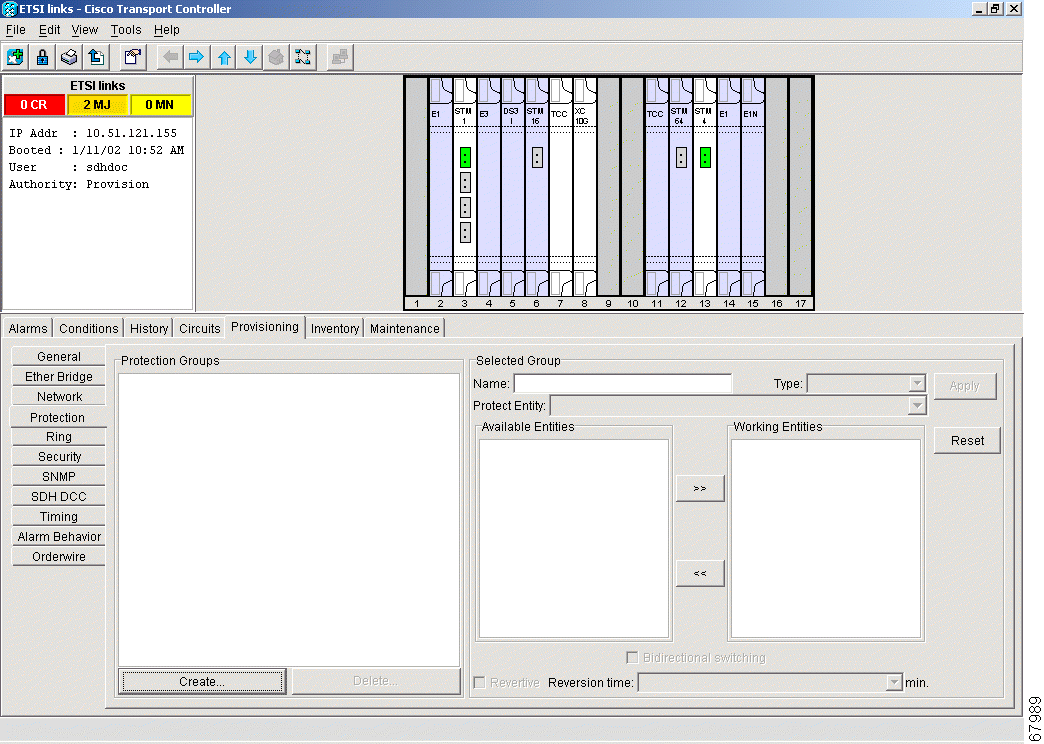
Step 1 In node view, click the Maintenance > Protection tabs.
Step 2 Click the protection group that contains Slot 3 or Slot 15 (where you will install the E1-N14 card that protects the others).
Step 3 Make sure the slot you are upgrading is not carrying working traffic. In the Selected Group list, the protect slot must say Protect/Standby and not Protect/Active. If the protect slot status is Protect/Active, use the following steps to switch traffic to the working card:
a. Under Selected Group, click the protect card.
b. Next to Switch Commands, click Switch.
c. The working slot should change to Working/Active and the protect slot should change to Protect/Standby. If they do not change, do not continue. Troubleshoot the working card and slot to determine why the card cannot carry working traffic.
d. Next to Switch Commands, select Clear.
Figure 7-5 Viewing slot protection status
Step 4 Repeat Steps 1 - 3 for each protection group that you need to convert.
Step 5 Verify that no standing alarms exist for any of the E1-N14 cards that you are converting. If alarms exist and you have difficulty clearing them, contact your next level of support.
Step 6 Click the Provisioning > Protection tabs.
Step 7 Click the 1:1 protection group containing the cards that you will move into the new protection group.
Step 8 Click Delete.
Step 9 When the confirmation dialog displays, click Yes.
Step 10 Deleting the 1:1 protection groups does not disrupt service. However, no protection bandwidth exists for the working circuits until you complete the 1:N protection procedure. Therefore, complete this procedure as quickly as possible.
Step 11 If needed, repeat Steps 8 - 10 for other protection groups.
Step 12 Verify that the card boots up properly.
Step 13 Click the Provisioning > Protection tabs.
Step 14 Click Create. The Create Protection Group dialog opens with the protect card in the Protect Card field and the available cards in the Available Cards field.
Step 15 Type a name for the protection group in the Name field (optional).
Step 16 Click Type and choose 1:N (card) from the pull-down menu.
Step 17 Verify that the E1-N14 card appears in the ProtectCard field.
Step 18 Under Available Cards, highlight the cards that you want in the protection group. Click the arrow (>>) tab to move the cards to the Working Cards list.
Step 19 Click OK.
The protection group appears in the Protection Groups list on the Protection subtab.
7.3.2 Convert DS-3i-N-12 Cards From 1:1 to 1:N Protection
Purpose
Verify that the ONS 15454 shelf is ready for turnup.
Tools/Equipment
Computer with CTC
Prerequisite procedures
All shelf and card installation procedures; protection card installed in slot 3 (for protection of cards in slots 1 to 6); or protection card installed in slot 15 (for protection of cards in slots 12 to 17)
Required/As Needed
Optional
Onsite/Remote
Onsite or remote
Note This procedure assumes that DS-3i-N-12 cards are installed in Slots 1 - 6 and/or Slots 12 - 17.
Procedure: Convert DS-3i-N-12 Cards From 1:1 to 1:N Protection
Step 1 In node view, click the Maintenance > Protection tabs.
Step 2 Click the protection group containing Slot 3 or Slot 15 (where you will install the DS-3i-N-12 card).
Step 3 Make sure the slot you are upgrading is not carrying working traffic. In the Selected Group list, the protect slot must say Protect/Standby and not Protect/Active. If the protect slot status is Protect/Active, use the following steps to switch traffic to the working card:
a. Under Selected Group, click the protect card.
b. Next to Switch Commands, click Switch.
The working slot should change to Working/Active and the protect slot should change to Protect/Standby. If they fail to change, do not continue. Troubleshoot the working card and slot to determine why the card cannot carry working traffic.
c. Next to Switch Commands, click Clear.
Step 4 Repeat Steps 2 and 3 for each protection group that you need to convert.
Step 5 Verify that no standing alarms exist for any of the DS-3i-N-12 cards you are converting. If alarms exist and you have difficulty clearing them, contact your next level of support.
Step 6 Click the Provisioning > Protection tabs.
Step 7 Click a 1:1 protection group containing the cards that you will move into the new protection group.
Step 8 Click Delete.
Step 9 When the confirmation dialog displays, click Yes.
Step 10 Deleting the 1:1 protection groups will not disrupt service. However, no protection bandwidth exists for the working circuits until the 1:N protection procedure is completed. Do not delay when completing this procedure.
Step 11 If you are deleting more than one protection group, repeat Steps 6 - 8 for each group.
Step 12 Verify that the card boots up properly.
Step 13 Click the Provisioning > Protection tabs.
Step 14 Click Create.
Step 15 The Create Protection Group dialog shows the protect card in the Protect Card field and the available cards in the Available Cards field.
Step 16 Type a name for the protection group in the Name field (optional).
Step 17 Click Type, and from the pull-down menu choose 1:N (card).
Step 18 Verify that the DS-3i-N-12 card appears in the Protect Card field.
Step 19 In the Available Cards list, highlight the cards that you want in the protection group. Click the arrow (>>) tab to move the cards to the Working Cards list.
Step 20 Click OK.
The protection group should appear in the Protection Groups list on the Protection subtab.
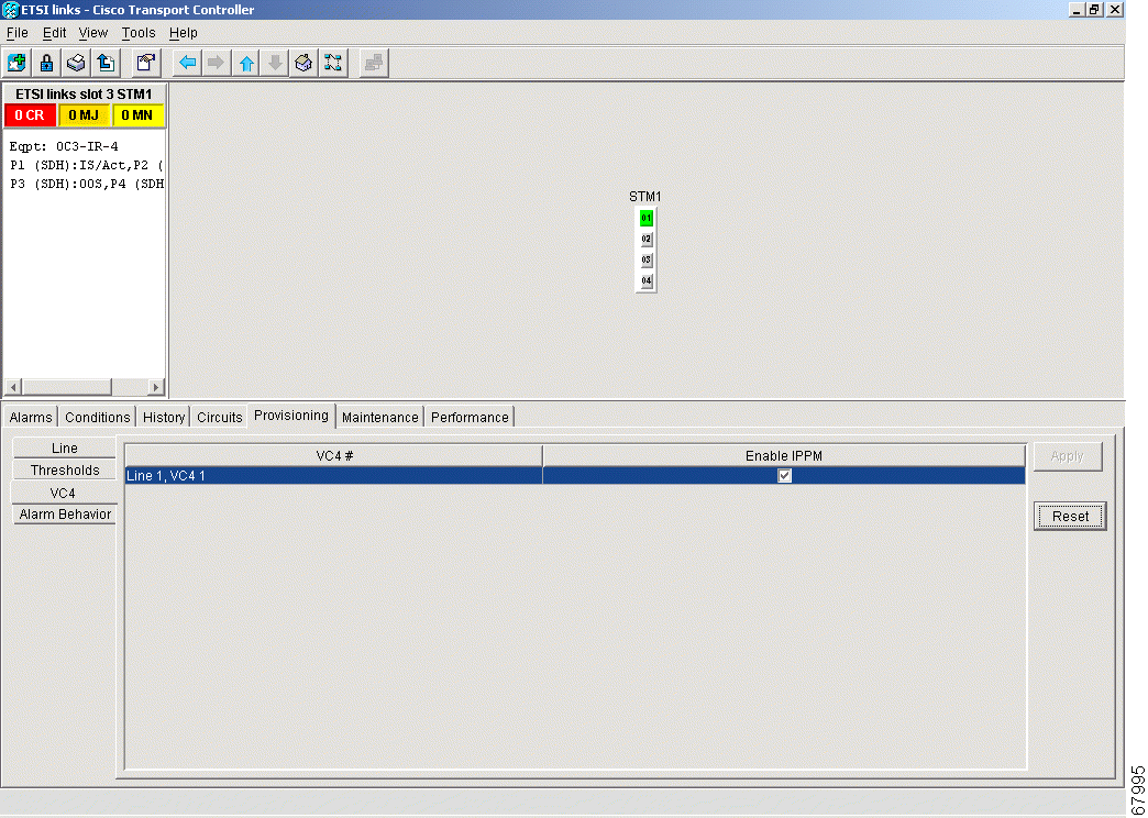
Intermediate-Path Performance Monitoring (IPPM) allows you to transparently monitor traffic originating on E-1, E-3, and DS-3 cards (Path Terminating Equipment) as it passes through STM-1, STM-4, STM-16, and STM-64 cards (Line Terminating Equipment). To use IPPM, you create the VC4 circuit on the E-1, E-3 or DS-3 cards, then enable IPPM on the STM-N cards that carry the circuit.
Near-end performance monitoring data on individual VC4 payloads is available by enabling IPPM.
For example, suppose you have a VC4 circuit that originates and terminates on E-N cards at Nodes 1 and 4. You want to monitor the circuit as it passes through STM-N cards at Nodes 2 and 3. To do this, open the STM-N card, select the Provisioning > VC4 tabs, and check Enable IPPM for the appropriate VC4, in this example, Line 1, VC4 1 (Figure 7-6).
Figure 7-6 IPPM provisioned for VC4 on an OC-3 STM-1 card
After enabling IPPM, performance is displayed on the Performance tab for the STM-N card. IPPM enables per-path statistics for VC4 CV-P (coding violations), VC4 ES-P (errored seconds), VC4 FC-P (failure count), VC4 SES-P (severely errored seconds), and VC4 UAS-P (unavailable seconds). Only one VC4 per port can be monitored at one time. For additional information about ONS 15454 SDH performance monitoring, see to "SDH Performance Monitoring."
7.5 Provisioning Optical Cards
This section explains how to provision line and threshold settings for OC-N /STM-N cards and how to provision OC-N /STM-N cards for SDH.
Note The general expression OC-N/STM-N is chosen because the numbering in SONET (OC-N) and SDH
(STM-N) are not the same. OC-3 corresponds with STM-1, etc.
The OC-N /STM-N abbreviation stands for any of the following cards:
OC3 IR 4/STM1 SH 1310
OC12 IR/STM4 SH 1310
OC12 LR/STM4 LH 1310
OC12 LR/STM4 LH 1550
OC48 IR/STM16 SH AS 1310
OC48 LR/STM16 LH AS 1550
OC48 ELR/STM16 EH 100 GHz
OC192 LR/STM64 LH 1550
The OC48 ELR/STM16 EH 100 GHz cards are available in eighteen different wavelength versions for Dense Wavelength Division Multiplexing DWDM; refer to the OC48 ELR/STM 16 EH 100 GHz Card Specifications section in the Cisco ONS 15454 SDH Troubleshooting and Maintenance Guide, Release 3.3 for a table of available wavelengths. In the following tables, all these cards are abbreviated as STM-1, STM-4, STM-16, and STM-64.
7.5.1 Modifying Transmission Quality
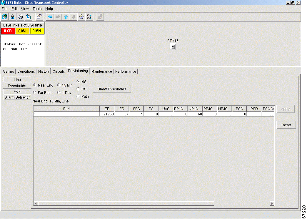
The STM-1, STM-4, STM-16 and STM-64 cards are pre-provisioned with settings that you can modify to manage transmission quality. For each optical card, you can specify thresholds for near and far end nodes at the Line, Section, and Path levels for 15-minute and one day intervals. Depending on the card, you can specify Line, Section, and Path thresholds.
Procedure: Provision Line Transmission Settings for OC-N /STM-N Cards
Purpose
Setting line parameters for optical cards
Tools/Equipment
Computer with CTC
Prerequisite procedures
All shelf and card installation procedures
Required/As Needed
Required
Onsite/Remote
Onsite or remote
Step 1 Display the OC-N /STM-N card in CTC card view.
The ONS 15454 SDH currently supports 1+1 span protection to create redundancy for optical cards. Optical cards in any two slots can be paired for protection. 1+1 protection pairs a single working card with a single dedicated protect card. If the working card fails, the protect cards takes over.
With non-revertive 1+1 protection, when a failure occurs and the signal switches from the working card to the protect card, the signal stays switched to the protect card until it is manually switched back. Revertive 1+1 protection automatically switches the signal back to the working card when the working card comes back online.
7.7 Provisioning Ethernet Cards
Three Ethernet cards are available for the ONS15454 SDH.