This chapter explains how to set up a Cisco ONS 15454 SDH node using Cisco Transport Controller (CTC). Table 3-1 lists node setup topics. Table 3-2 lists node setup procedures. The chapter also includes a list of required information for node setup. Refer to "Set up PC and Log into CTC" for CTC setup procedures.
Longitude and latitude (optional). You can find the longitude and latitude for cities from the Latitude and Longitude of World Cities website (http://www.infoplease.com/ipa/A0001769.html).
Date and time
Time zone
If the ONS 15454 SDH will be connected to a network, you will need:
The IP address and subnet mask to assign to the node
The IP address of the default router
If Dynamic Host Configuration Protocol is used, you will need the IP address of the DHCP server
If you are responsible for setting up IP networking for the ONS 15454 SDH network, see "IP Networking" for more information.
To create card protection groups, you will need to know:
The card protection scheme that will be used and what cards will be included in it
The SDH protection topology that will be used for the node
Note You must be able to log into the node to complete node provisioning. If you cannot log into the node,
see the "Setting Up the CTC Computer"
section.
3.2 Setting Up Basic Node Information
Setting basic information for each Cisco ONS 15454 SDH node is one of the first provisioning tasks you perform. This information includes node name, location, contact, latitude, longitude, dates, and time.
Procedure: Add the Node Name, Contact, Location, Date, and Time
Purpose
Use this procedure to set node identification and other node-specific information.
Step 1 Start CTC for an ONS 15454 SDH node. The CTC node view is displayed.
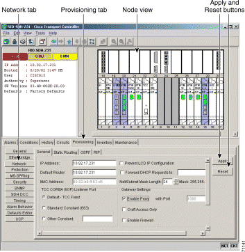
Step 2 Click the Provisioning > General tabs.
Figure 3-1 Setting up general node information
Step 3 Enter the following:
Node Name—Type a name for the node. For TL1 compliance, names must begin with an alpha character and have no more than 20 alphanumeric characters. (TL1 is not available in SDH Software R3.3.)
Contact—Type the name of the node contact person and the phone number (optional).
Location—Type the node location, for example, a city name or specific office location (optional).
Latitude—Enter the node latitude: N (North) or S (South), degrees, and minutes (optional).
Longitude—Enter the node longitude: E (East) or W (West), degrees, and minutes (optional).
CTC uses the latitude and longitude to position node icons on the network view map.
Note You can also position nodes manually by pressing Ctrl and dragging the node icon to a new location.
To convert a coordinate in degrees to degrees and minutes, multiply the number after the decimal by 60. For example, the latitude 38.250739 converts to 38 degrees, 15 minutes (.250739 x 60 = 15.0443, rounded to the nearest whole number).
Use SNTP/NTP Server—When checked, CTC uses a Simple Network Time Protocol (SNTP) server or Network Time Protocol (NTP) server to set the date and time of the node. Using an SNTP/NTP server ensures that all ONS 15454 SDH network nodes use the same date and time reference. The server synchronizes the nodes time after power outages or software upgrades.
If you check Use SNTP/NTP Server, type the server's IP address in the next field. If you do not use an SNTP/NTP server, complete the Date, Time, and Time Zone fields. The ONS 15454 SDH will use these fields for alarm dates and times. (CTC displays all alarms in the login node's time zone for cross network consistency.)
Date—Type the current date if you did not select Use SNTP/NTP Server.
Time—Type the current time if you did not select Use SNTP/NTP Server.
Time Zone—Select the time zone if you did not select Use SNTP/NTP Server.
Step 4 Click Apply.
3.3 Setting Up Network Information
Before you connect a node to other nodes or to a LAN, you must change the default IP address that is shipped with each ONS 15454 SDH (192.168.1.1). IP addresses are unique identifiers for devices—called hosts—that connect to TCP/IP networks. Every IP address includes a network number, which is assigned to an organization, and a host (device) number, which the organization's LAN administrator assigns to an individual network device.
Subnetting enables LAN administrators to create subnetworks that are transparent to the Internet. Within networks, ONS 15454 SDHs often exist as subnetworks, which are created by adding a subnet mask to the ONS 15454 SDH IP address.
Procedure: Set Up Network Information
Purpose
Use this procedure to start provisioning a network. Additional ONS 15454 SDH networking information and procedures, including IP addressing examples, static route scenarios and Open Shortest Path First (OSPF) protocol options are provided in Chapter 3, "IP Networking."
Prerequisite Procedures
The IP address and subnet mask to assign to the node
The IP address of the default router
If Dynamic Host Configuration Protocol is used, you will need the IP address of the DHCP server
Onsite/Remote
Onsite or remote
Step 1 Log into CTC or navigate to the node view. Click the Provisioning > Network tabs (Figure 3-2).
Figure 3-2 Setting up general network information
Step 2 Complete the following:
IP Address—Type the IP address assigned to the ONS 15454 SDH node.
Default Router—Check this field if the ONS 15454 SDH must communicate with a device on a network that the ONS 15454 SDH is not connected to. The ONS 15454 SDH forwards the packets to the default router. Type the IP address of the router in this field. If the ONS 15454 SDH is not connected to a LAN, leave the field blank.
Subnet Mask Length—If the ONS 15454 SDH is part of a subnet, type the subnet mask length (decimal number representing the subnet mask length in bits) or click the arrows to adjust the subnet mask length. The subnet mask length is the same for all ONS 15454 SDHs in the same subnet.
Note The MAC Address is read only. It displays the ONS 15454 SDH
address used by the IEEE 802 Media Access Control (MAC) layer.
Forward DHCP Requests To—When checked, this field forwards Dynamic Host Configuration Protocol requests to the IP address entered in the Request To field. DHCP is a TCP/IP protocol that enables CTC computers to get temporary IP addresses from a server. If you enable DHCP, CTC computers that are directly connected to an ONS 15454 SDH node can find temporary IP addresses from the DHCP server.
Craft Access Only—When this choice is enabled, the ONS 15454 SDH neither installs nor advertises default or static routes. CTC computers can communicate with the ONS 15454 SDH, but they cannot communicate directly with any other DCC-connected ONS 15454 SDH.
In a configuration where all nodes are on the same subnet, if you start a CTC session before proper provisioning, the login node will appear grey in the CTC network view. Other CTC users will not be able to open the grey-colored node to access their node. Provision a static route on the node that is LAN-connected, or, if you are directly connected to the node, provision craft access. For procedures, see "Scenario 5: Using Static Routes to Connect to LANs" section, or "Scenario 8: Provisioning the ONS 15454 SDH Proxy Server" section.
Enable Proxy—When this choice is enabled, the ONS 15454 SDH responds to CTC client requests with a list of DCC-connected ONS 15454 SDHs for which the node serves as a proxy. The CTC client establishes connections through the proxy server for any ONS 15454 SDH in the returned list. By using the proxy, the CTC client can connect to nodes that the PC on which the CTC client runs cannot access. If Enable Proxy is off, the node responds to CTC requests with an empty list, indicating that it is not willing to serve as a proxy.
Enable Firewall—If this choice is selected, the node prevents IP traffic from being routed between the DCC and the LAN port. The ONS 15454 SDH can communicate with machines connected to the LAN port or connected through the DCC. However, the DCC-connected machines cannot communicate with the LAN-connected machines, and the LAN-connected machines cannot communicate with the DCC-connected machines. A CTC node using the LAN to reach the firewalling node can use the proxy capability to manage the unreachable, DCC-connected nodes. CTC connected to a DCC-connected node can only manage other DCC-connected nodes and the firewall itself.
Step 3 Click Apply.
Step 4 Click Yes on the confirmation dialog box.
Both ONS 15454 SDH TCC-I cards will reboot, one at a time.
Note CTC software does not monitor for the presence or absence of FMECs unless the TCC-I(s) card is
Active/Stby. During transitional states such as power-up or TCC-I reset, CTC ignores the FMEC
inventory displayed in node view.
Procedure: Change IP Address, Default Router, and Network Mask Using the LCD
Purpose
You can change the ONS 15454 SDH IP address, subnet mask, and default router address using the Slot, Status, and Port buttons on the front panel LCD.
Prerequisite Procedures
The IP address and subnet mask to assign to the node
The IP address of the default router
If Dynamic Host Configuration Protocol is used, you will need the IP address of the DHCP server
Onsite/Remote
Onsite or remote
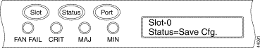
Step 1 On the ONS 15454 SDH front panel, repeatedly press the Slot button until Node appears on the LCD.
Note The LCD reverts to normal display mode after 5 seconds of button inactivity.
Step 2 Repeatedly press the Port button until the following displays:
To change the node IP address, Status=IpAddress (Figure 3-3)
To change the node network mask, Status=Net Mask
To change the default router IP address, Status=Default Rtr
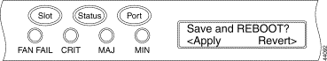
Figure 3-3 Selecting the IP address option
Step 3 Press the Status button to display the node IP address (Figure 3-4), the node subnet mask length, or the default router IP address.
Figure 3-4 Changing the IP address
Step 4 Push the Slot button to move to the IP address or subnet mask digit you need to change. The selected digit flashes.
Step 5 Press the Port button to cycle the IP address or subnet mask digit to the correct digit.
Step 6 When the change is complete, press the Status button to return to the Node menu.
Step 7 Repeatedly press the Port button until the Save Configuration option appears (Figure 3-5).
Figure 3-5 Selecting the Save Configuration option
Step 8 Press the Status button to select the Save Configuration option.
Step 9 Press the Slot button to save the new IP address configuration. (Or press Port to cancel the configuration.)
Saving the new configuration causes the TCC-I cards to reboot. During the reboot, a "Saving Changes - TCC Reset" message displays on the LCD. The LCD returns to the normal alternating display after the TCC-I reboot is complete.
Note CTC software does not monitor for the presence or absence of FMECs unless the TCC-I(s) card is
active/standby. During transitional states such as power-up or TCC-I reset, CTC ignores the FMEC
inventory displayed in node view.
3.4 Creating Users and Setting Security
Use the CISCO15 user, provided with each ONS 15454 SDH, to set up other ONS 15454 SDH users. You can add up to 500 users to one ONS 15454 SDH. Each ONS 15454 SDH user can be assigned one of the following security levels:
Retrieve users can retrieve and view CTC information but cannot set or modify parameters.
Maintenance users can access only the ONS 15454 SDH maintenance options.
Provisioning users can access provisioning and maintenance options.
Superusers can perform all of the functions of the other security levels as well as set names, passwords, and security levels for other users.
Each ONS 15454 SDH user has a specified amount of time that he or she can leave the system idle before the CTC window is locked. The lockouts prevent unauthorized users from making changes. Higher-level users have shorter idle times, as shown in Table 3-3.
Table 3-3 ONS 15454 SDH User Idle Times
Security Level
Idle Time
Superuser
15 minutes
Provisioning
30 minutes
Maintenance
60 minutes
Retrieve
Unlimited
Table 3-4 shows the actions that each user can perform in node view. In the tables below, Yes means the user can use the specified tab or screen. Table cells with dashes (—) mean the user cannot use the specified tab or screen.
Table 3-4 ONS 15454 SDH Security Levels—Node View
CTC Tab
Subtab
Actions
Retrieve
Maint.
Provision
Superuser
Alarms
—
Synchronize alarms
Yes
Yes
Yes
Yes
Conditions
—
Retrieve conditions
Yes
Yes
Yes
Yes
History
Session
Read only
Yes
Yes
Yes
Yes
Node
Retrieve alarms/events
Yes
Yes
Yes
Yes
Circuits
—
Create, delete, or edit circuits
—
—
Yes
Yes
Search for circuits
Yes
Yes
Yes
Yes
Provisioning
General
Edit
—
—
Yes
Yes
Ether
Bridge
Spanning Trees: Edit
—
—
Yes
Yes
Thresholds: Create, or delete
—
—
Yes
Yes
Network
General: Edit
—
—
—
Yes
Static Routing: Create, edit, or delete
—
—
—
Yes
OSPF: Edit
—
—
—
Yes
Protection
Create, delete, or edit
—
—
Yes
Yes
Browse groups
Yes
Yes
Yes
Yes
Ring
All (MS-SPRing)
—
—
Yes
Yes
Security
Create or delete
—
—
—
Yes
Change password
Same User
Same User
Same User
All Users
SNMP
Create, delete, or edit
—
—
—
Yes
Browse trap destinations
Yes
Yes
Yes
Yes
SDH DCC
Create, or delete
—
—
—
Yes
View SDCC Terminations and DCC Tunnel Connections
Yes
Yes
Yes
Yes
Timing
Edit
Partial Edit
Partial Edit
Yes
Yes
Alarm Behavior
Edit
—
—
Yes
Yes
Orderwire
Create, or delete
—
—
Yes
Yes
Inventory
—
Delete card
—
—
Yes
Yes
Reset card
—
Yes
Yes
Yes
View equipment information
Yes
Yes
Yes
Yes
Maintenance
Database
Backup, or restore
—
—
—
Yes
Ether Bridge
Spanning Tree Retrieve
Yes
Yes
Yes
Yes
Spanning Tree Clear/Clear all
—
Yes
Yes
Yes
MAC Table Retrieve
Yes
Yes
Yes
Yes
MAC Table Clear/Clear all
—
Yes
Yes
Yes
Trunk Utilization Refresh
Yes
Yes
Yes
Yes
Protection
Switch/lock out operations
—
Yes
Yes
Yes
Ring
MS-SPRing maintenance
—
Yes
Yes
Yes
Software
Download/Activate/Revert
—
—
—
Yes
XC Cards
Switch/Lock/Unlock
—
Yes
Yes
Yes
Diagnostic
Retrieve Diagnostics File
—
—
—
Yes
Lamp Test (Will be available for Maintenance, Provisioning, and Super users in Software R3.4.)
—
—
—
Yes
Timing
Edit
—
Yes
Yes
Yes
Audit
Retrieve Audit Trail
Yes
Yes
Yes
Yes
Routing Table
Read only
Yes
Yes
Yes
Yes
Procedure: Create a New User with Security Settings
You can perform ONS 15454 SDH user management tasks from network or node view. In network view, you can add, edit, or delete users from multiple nodes at one time. If you perform user management tasks in node view, you can only add, edit, or delete users from that node.
Note You must add the same user name and password to each node the user will access.
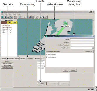
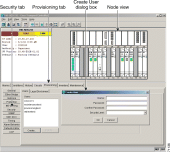
Step 1 In network view, select the Provisioning > Security tabs.
Step 2 On the Security pane, click Create.
Figure 3-7 Creating new users from the network view
Step 3 In the Create User dialog box, enter the following:
Name—Type the user name.
Password—Type the user password. The password must be a minimum of six and a maximum of ten alphanumeric characters (for example, ILM+12), where at least one character is numerical (0-9) and at least one special character is used (+, #,%).
Confirm Password—Type the password again to confirm it.
Security Level—Select the user's security level.
Step 4 Under "Select applicable nodes," deselect any nodes where you do not want to add the user (all network nodes are selected by default).
Step 5 Click OK.
Note New users can also be created from node view. If you add a user in node view, you can only add, edit,
or delete users from that node (Figure
3-8).
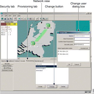
Step 1 In network view, select the Provisioning > Security tabs.
Step 2 Click a name under the list of users.
Figure 3-9 Changing a user's security settings from the network view
Step 3 On the Selected User dialog box, edit the user information: name, password, password confirmation, and/or security level. (A Superuser does not need to enter an old password. Other users must enter their old password when changing their own passwords.)
Note You cannot change the CISCO15 user name.
Step 4 If you do not want the user changes to apply to all network nodes, deselect the nodes that you do not want to change in the Change Users dialog box.
Step 5 Click OK.
Changed user permissions and access levels do not take effect until the user logs out of CTC and logs back in.
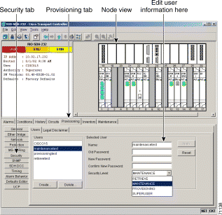
Note User security settings can also be changed from node view
(Figure 3-10).
Figure 3-10 Changing a user's security settings from the node view
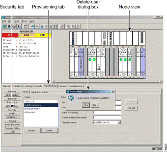
Step 1 In network view, select the Provisioning > Security tabs.
Step 2 Click Delete.
Figure 3-11 Deleting a user from the network view
Step 3 On the Delete User dialog box, enter the name of the user you want to delete.
Step 4 If you do not want to delete the user from all network nodes, deselect the nodes.
Step 5 Click OK and click Apply.
Note User security settings can also be deleted from node view
(Figure 3-12).
Figure 3-12 Deleting a user from the node view
3.5 Setting Up ONS 15454 SDH Timing
SDH timing parameters must be set for each ONS 15454 SDH.
3.5.1 Timing Sources and Modes
Each ONS 15454 SDH independently accepts its timing reference from one of three sources:
The Timing A and Timing B connector on the MIC-C/T/P FMEC in Slot 24.
Note CTC refers to Timing A and Timing B as BITS (Building Integrated Timing Supply) 1 and BITS 2.
An STM-N card installed in the ONS 15454 SDH. The STM-N card is connected to a node that receives timing through a BITS source.
The internal ST3 clock on the TCC-I card.
You can set ONS 15454 SDH timing to one of three modes: external, line, or mixed. If timing is coming from the MIC-C/T/P FMEC timing connector, set ONS 15454 SDH timing to external. If the timing comes from an STM-N card, set the timing to line.
Note The line timing mode is not available for 64 KHz.
In typical ONS 15454 SDH networks:
One node is set to external. The external node derives its timing from a MIC-C/T/P FMEC timing connector. The MIC-C/T/P FMEC, in turn, derives its timing from a Primary Reference Source (PRS) such as a Stratum 1 clock or global positioning satellite (GPS) signal.
The other nodes are set to line. The line nodes derive timing from the externally-timed node through the STM-N trunk cards.
You can set three timing references for each ONS 15454 SDH. The first two references are typically two FMEC-level sources, or two line-level sources optically connected to a node with a BITS source. The third reference is the internal clock provided on every ONS 15454 SDH TCC-I card. This clock is a Stratum 3 (ST3). If an ONS 15454 SDH becomes isolated, timing is maintained at the ST3 level.
Caution Mixed timing allows you to select both external and line timing sources. However, Cisco does not recommend its use because it can create timing loops. Use this mode with caution.
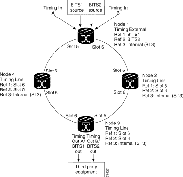
3.5.2 Network Timing Example
Figure 3-13 shows an ONS 15454 SDH network timing setup example. Node 1 is set to external timing. Two timing references are set to BITS. These are Stratum 1 timing sources connected to the MIC-C/T/P FMEC. The third reference is set to internal clock. The Timing A and Timing B out connectors on the MIC-C/T/P FMEC of Node 3 are used to provide timing to outside equipment.
In the example, Slots 5 and 6 contain the trunk cards. Timing at Nodes 2, 3, and 4 is set to line, and the timing references are set to the trunk cards based on distance from the MIC-C/T/P FMEC. Reference 1 is set to the trunk card closest to the timing source. At Node 2, Reference 1 is Slot 5 because it is connected to Node 1. At Node 4, Reference 1 is set to Slot 6 because it is connected to Node 1. At Node 3, Reference 1 could be either trunk card because they are equal distance from Node 1.
Figure 3-13 An ONS 15454 SDH timing example
3.5.3 Synchronization Status Messaging
Synchronization Status Messaging (SSM) communicates information about the quality of the timing source. The SSM supported in SDH is G.811, STU, G812T, G812L, SETS, DUS (ordered from high quality to low quality). SSM messages are carried on bits 5 to 8 of SDH overhead byte S1. They enable SDH devices to automatically select the highest quality timing reference and to avoid timing loops.
Note The message set in San1 to San4 is a copy of the set defined in SDH bits 5 to 8 of byte S1.
Table 3-5 Assignment of Bit Patterns as Shown in ITU G.704
Procedure: Set up External, Line, or Mixed Timing for the ONS 15454 SDH
Note CTC refers to Timing A and Timing B as BITS (Building Integrated Timing Supply) 1 and BITS 2.
The MIC-C/T/P FMEC connector is labeled as Timing A and Timing B.
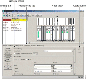
Step 1 From the CTC node view, click the Provisioning > Timing tabs (Figure 3-14).
Figure 3-14 Setting up external, line, or mixed ONS 15454 SDH timing
Step 2 In the General Timing section, complete the following information:
Timing Mode—Choose External if the ONS 15454 SDH derives its timing from a MIC-C/T/P FMEC; choose Line if timing is derived from an STM-N card that is optically connected to the timing node. A third option, Mixed, allows you to set external and line timing references. (Because Mixed timing may cause timing loops, Cisco does not recommend its use. Use this mode with care.)
Revertive—If this checkbox is selected, the ONS 15454 SDH reverts to a primary reference source after the conditions that caused it to switch to a secondary timing reference are corrected.
Revertive Time—If Revertive is checked, indicate the amount of time the ONS 15454 SDH will wait before reverting to its primary timing source.
Step 3 In the BITS Facilities section, complete the following information:
Note The BITS Facilities section sets the parameters for your BITS1 and
BITS2 timing references. Many of these settings are determined by the timing source
manufacturer. If equipment is timed through BITS Out, you can set timing parameters to
meet the requirements of the equipment.
E1, 2.048 MHz, 64 KHz—Choose E1, 2.048 MHz, or 64 KHz depending on the signal supported in your market. For example, 64 KHz is used in Japan. E1, 2.048 MHz, and 64 KHz are physical signal modes used to transmit the external clock (from a GPS for example) to BITS.
State—Set the BITS reference to IS (In Service) or OOS (Out of Service). For nodes set to Line timing with no equipment timed through BITS Out, set Stateto OOS. For nodes using External timing or Line timing with equipment timed through BITS Out, set State to IS.
Coding—Choose the coding used by your BITS reference, either HDB3 or AMI. If you selected 2.048 MHz, or 64 KHz, the coding option is disabled.
Framing—Choose the framing used by your BITS reference, either unframed, FAS, FAS + CAS, FAS + CRC, or FAS + CAS + CRC. If you selected 2.048 MHz, or 64 KHz, the framing option is disabled.
Sync Messaging—Select the checkbox to enable synchronization status message (SSM). SSM is used to deliver clock quality. The SSM supported in SDH is G811, STU, G812T, G812L, SETS, DUS (ordered from high quality to low quality). If you selected 2.048 MHz, or 64 KHz, the SSM option is disabled.
AIS Threshold—Sets the quality level at which a node sends an Alarm Indication Signal (AIS) from the BITS 1 Out and BITS 2 Out FMEC connector. When a node times at or below the AIS Threshold quality, an AIS is sent. (The AIS Threshold is used when Sync. Messaging is disabled or framing is set to unframed, FAS, or FAS + CAS.)
LBO—Choose a BITS cable length. Line build out (LBO) relates to the BITS cable length.
Sa bit—Choose one of 5 Sa bits (Sa4, Sa5, Sa6, Sa7, and Sa8). The Sa bit transmits the SSM message. If you selected 2.048 MHz or 64 KHz, the Sa bit option is disabled.
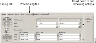
Step 4 Under Reference Lists, complete the following information:
Figure 3-15 Reference list on the ONS 15454 SDH timing tab
Note Reference lists define up to three timing references for the node and up to six BITS Out
references. BITS Out references define the timing references used by
equipment attached to the node's MIC-C/T/P FMEC Timing A and Timing B Out connector.
If you attach equipment to the Timing A or B Out connector, you normally attach it to a node
with Line mode because equipment near the External timing reference can be directly wired
to the reference.
NE Reference—Allows you to define three timing references (Ref 1, Ref 2, Ref 3). The node uses Reference 1 unless a failure occurs to that reference, in which case, the node uses Reference 2. If Reference 2 fails, the node uses Reference 3, which is typically set to Internal Clock. The internal clock is the Stratum 3 clock provided on the TCC-I. The options displayed depend on the Timing Mode setting.
Timing Mode set to External—Your options are BITS1, BITS2, and Internal Clock.
Timing Mode set to Line—Your options are the node's working optical cards and Internal Clock. Select the cards/ports that are directly or indirectly connected to the node wired to the BITS source, that is, select the node's trunk cards. Set Reference 1 to the trunk card that is closest to the BITS source. For example, if Slot 5 is connected to the node wired to the BITS source, select Slot 5 as Reference 1.
Timing Mode set to Mixed—Both BITS and optical cards are available, allowing you to set a mixture of external BITS and optical trunk cards as timing references.
BITS 1 Out/BITS 2 Out—Define the timing references for equipment connected to the Timing A or B Out FMEC connector. Normally, Timing Out is used with Line nodes, so the options displayed are the working optical cards. Timing A and Timing B Out are enabled as soon as BITS-1 and BITS-2 facilities are placed in service.
Step 5 Click Apply.
Note Refer to the Cisco ONS 15454 SDH Troubleshooting and Maintenance Guide for timing-related
alarms.
Procedure: Set Up Internal Timing for the ONS 15454 SDH
Note CTC refers to Timing A and Timing B as BITS (Building Integrated Timing
Supply) 1 and BITS 2. The MIC-C/T/P FMEC connector is labeled as Timing A and Timing B.
Purpose
If no BITS source is available, you can set up internal timing by timing all nodes in the ring from the internal clock of one node. Internal timing is Stratum 3 and not intended for permanent use. All ONS 15454 SDHs should be timed to a Stratum 2 or better primary reference source.
Step 1 Log into the node that will serve as the timing source.
Step 2 From the CTC node view, click the Provisioning > Timing tabs (Figure 3-16).
Figure 3-16 Setting up internal ONS 15454 SDH timing
Step 3 In the General Timing section, enter the following:
Timing Mode—Choose External.
Revertive—Not relevant for internal timing; the default setting (checked) is sufficient.
Revertive Time—Not relevant for internal timing; the default setting (5 minutes) is sufficient.
Step 4 In the BITS Facilities section, enter the following information:
E1, 2.048 MHz, 64 KHz—Choose E1, 2.048 MHz, or 64 KHz depending on the signal supported in your market. For example, 64 KHz is used in Japan. E1, 2.048 MHz, and 64 KHz are physical signal modes used to transmit the external clock (from a GPS for example) to BITS.
State—Set BITS 1 and BITS 2 to OOS (Out of Service).
Coding—Not relevant for internal timing; the default (HDB3) is sufficient.
Framing—Not relevant for internal timing; the default (FAS + CAS + CRC) is sufficient.
Sync Messaging—The box is checked automatically. Synchronization status message (SSM) is used to deliver clock quality. The SSM supported in SDH is G811, STU, G812T, G812L, SETS, DUS (ordered from high quality to low quality). If you selected 2.048 MHz, or 64 KHz, the SSM option is disabled.
AIS Threshold—Not relevant for internal timing.
LBO—Not relevant for internal timing; line build out (LBO) relates to the BITS cable length.
Sa bit—Not relevant for internal timing; the Sa bit is used to transmit the SSM message.
Step 5 In the Reference Lists section, enter the following information:
NE Reference
Ref1—Set to Internal Clock.
Ref2—Set to Internal Clock.
Ref3—Set to Internal Clock.
BITS 1 Out/BITS 2 Out—Set to None
Step 6 Click Apply.
Step 7 Log into a node that will be timed from the node set up in Step 1 to Step 6.
Step 8 In the CTC node view, click the Provisioning > Timing tabs.
Step 9 In the General Timing section, enter the following:
Timing Mode—Set to Line.
Revertive—Not relevant for internal timing; the default setting (checked) is sufficient.
Revertive Time—The default setting (5 minutes) is sufficient.
Step 10 In the Reference Lists section, enter the following:
NEReference
Ref-1—Use the pull-down menu to choose the STM-N trunk card with the closest connection to the node in Step 3.
Ref-2—Use the pull-down menu to choose the STM-N trunk card with the next closest connection to the node in Step 3.
Ref-3—Use the pull-down menu to choose Internal Clock.
Step 11 Click Apply.
Step 12 Repeat Step 7 to Step 11 at each node that will be timed by the node serving as the timing source.
3.6 Creating Card ProtectionGroups
The ONS 15454 SDH provides several card protection methods. When you set up protection for ONS 15454 SDH cards, you must choose between maximum protection and maximum slot availability. The highest protection reduces the number of available card slots; the highest slot availability reduces the protection. Table 3-6 shows the protection types that can be set up for ONS 15454 SDH cards.
Table 3-6 Protection Types
Type
Cards
Description
1:1
E1-N-14
E3-12
DS3i-N-12
Pairs one working card with one protect card. Install the protect card in an odd-numbered slot and the working card in an even-numbered slot next to the protect slot towards the center, for example: protect in Slot 1, working in Slot 2; protect in Slot 3, working in Slot 4; protect in Slot 15, working in Slot 14.
1:N
E1-N-14
DS3i-N-12
Assigns one protect card for several working cards. The maximum is 1:5. Protect cards (E1-N-14, DS3i-N-12) must be installed in Slots 3 or 15 and the cards they protect must be on the same side of the shelf. Protect cards must match the cards they protect. For example, a E1-N-14 can only protect E1-N-14 cards. If a failure clears, traffic reverts to the working card after the reversion time has elapsed.
1+1
Any optical
Pairs a working optical port with a protect optical port. Protect ports must match the working ports. For example, Port 1 of an STM-1 card can only be protected by Port 1 of another STM-1 card. Cards do not need to be in adjoining slots.
Unprotected
Any
Unprotected cards can cause signal loss if a card fails or incurs a signal error. However, because no card slots are reserved for protection, unprotected schemes maximize the service available for use on the ONS 15454 SDH. Unprotected is the default protection type.
Procedure: Create Protection Groups
Purpose
Use this procedure to create card protection groups for the ONS 15454 SDH. Unprotected cards can cause signal loss if a card fails or incurs a signal error.
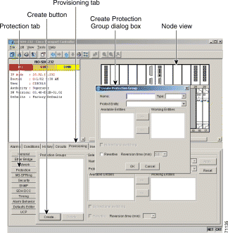
Step 1 From the CTC node view, click the Provisioning > Protection tabs.
Step 2 Under Protection Groups, click Create.
Figure 3-17 Creating card protection groups
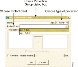
Step 3 In the Create Protection Group dialog box, enter the following:
Name—Type a name for the protection group. The name can have up to 32 alphanumeric characters.
Type—Choose the protection type (1:1, 1:N, or 1+1) from the pull-down menu. The protection selected determines the cards that are available to serve as protect and working cards. For example, if you choose 1:N protection, only E1-N-14 and DS3i-N-12 cards are displayed.
Protect Card or Port—Choose the protect card (if you are using 1:1 or 1:N) or protect port (if you are using 1+1) from the pull-down menu.
Based on these selections, a list of available working cards or ports is displayed under Available Cards or Available Ports. Figure 3-18 shows a 1:1 protection group.
Figure 3-18 Creating a 1:1 protection group
Step 4 From the Available Cards or Available Ports list, choose the card or port that you want to be the working card or port (the card(s) or port(s) that will be protected by the card or port selected in Protect Cards or Protect Ports). Click the top arrow button to move each card/port to the Working Cards or Working Ports list.
Step 5 Complete the remaining fields:
Bidirectional switching—(optical cards only) Click if you want both the transmit and the receive channels to switch if a failure occurs to one.
Revertive—If checked, the ONS 15454 SDH reverts traffic to the working card or port after failure conditions stay corrected for the amount of time entered in Reversion time.
Reversion time—If Revertive is checked, enter the amount of time that will elapse after a failure is corrected before the ONS 15454 SDH will revert to the working card or port.
Step 6 Click OK.
Caution Before running traffic on a protected card within a protection group, enable the ports of all protection group cards. See the "Set Card Ports In Service" procedure.
Step 1 From the CTC node view, click the Provisioning > Protection tabs.
Step 2 In the Protection Groups section, choose a protection group.
Step 3 In the Selected Group section, edit the fields as appropriate:
Name—Type a name for the protection group. The name can have up to 32 alphanumeric characters.
Type—Choose the protection type (1:1, 1:N, or 1+1) from the pull-down menu. The protection selected determines the cards that are available to serve as protect and working cards. For example, if you choose 1:1 protection, only E1, E3, and DS3i cards are displayed.
Protect Card or Port—Choose the protect card (if you are using 1:1 or 1:N) or protect port (if you are using 1+1) from the pull-down menu.
Based on these selections, a list of available working cards or ports is displayed under Available Cards or Available Ports.
Step 4 From the Available Cards or Available Ports list, choose the card or port that you want to be the working card or port (that is, the card(s) or port(s) that will be protected by the card or port selected in Protect Cards or Protect Ports). Click the top arrow button to move each card/port to the Working Cards or Working Ports list.
Step 5 Complete the remaining fields:
Bidirectional switching—(optical cards only) Click if you want both the transmit and the receive channels to switch if a failure occurs to one.
Revertive—If checked, the ONS 15454 SDH reverts traffic to the working card or port after a failure has been corrected for the amount of time entered in Reversion time.
Reversion time—If Revertive is checked, enter the amount of time following a failure correction that the ONS 15454 SDH will revert to the working card or port.
Step 6 Click Apply.
Procedure: Delete Protection Groups
Purpose
Use this procedure to delete a card protection group.
Step 1 From the CTC node view, click the Maintenance > Protection tabs.
Step 2 Verify that working traffic is not running on the protect card:
a. In the Protection Groups section, choose the group you want to delete.
b. In the Selected Group section, verify that the protect card is in standby mode. If the protect card is in standby mode, continue with Step 3. If it is active, complete Step c.
c. If the working card is in standby mode, manually switch traffic back to the working card. In the Selected Group pane, click the working card, then click Manual. Verify that the protect card switches to standby mode and the working card is active. If the protect card is standby, continue with Step 3. If the protect card is still active, do not continue. Begin troubleshooting procedures or call technical support.
Step 3 From the node view, click the Provisioning > Protection tabs.
Step 4 In the Protection Groups section, click a protection group.