|
|

The Cisco ONS 15454 SDH integrates Ethernet into an SDH time-division multiplexing (TDM) platform. The ONS 15454 SDH supports both E series Ethernet cards and the G series Ethernet card. This chapter describes the Ethernet capabilities of the ONS 15454 SDH, including:
The G1000-4 card reliably transports Ethernet and IP data across an SDH backbone. The G1000-4 card maps up to four gigabit Ethernet interfaces onto an SDH transport network. A single card provides scalable and provisionable transport bandwidth at the signal levels up to VC4-16C per card. The card provides line rate forwarding for all Ethernet frames (unicast, multicast, and broadcast) and can be configured to support Jumbo frames (defined as a maximum of 10,000 bytes).The G-series card incorporates features optimized for carrier-class applications such as:
The G1000-4 card allows an Ethernet private line service to be provisioned and managed very much like a traditional SONET or SDH line. G1000-4 card applications include providing carrier-grade Transparent LAN Services (TLS), 100 Mbps Ethernet private line services (when combined with an external 100 Mb Ethernet switch with Gigabit uplinks), and high availability transport for applications such as storage over MAN/WANs.
You can map the four ports on the G1000-4 independently to any combination of VC4, VC4-2c, VC4-3c, VC4-8c, and VC4-16c circuit sizes, provided the sum of the circuit sizes that terminate on a card do not exceed VC4-16c.
To support a gigabit Ethernet port at full line rate, an STM circuit with a capacity greater or equal to 1 Gbps (bidirectional 2 Gbps) is needed. A VC4-8c is the minimum circuit size that can support a gigabit Ethernet port at full line rate.The G1000-4 supports a maximum of two ports at full line rate.
Ethernet cards may be placed in any of the 12 multipurpose card slots. In most configurations, at least two of the 12 slots need to be reserved for optical trunk cards, such as the STM-64 card. The reserved slots give the ONS 15454 SDH a practical maximum of ten G1000-4 cards. The G1000-4 card requires the XC10G card to operate. For more information about the G1000-4 card specifications, see the Card Reference chapter in the Cisco ONS 15454 SDH Troubleshooting and Maintenance Guide.
The G1000-4 transmits and monitors the SDH J1 Path Trace byte in the same manner as ONS 15454 SDH cards. For more information, see the "Creating a Path Trace" section.
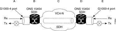
Figure 9-1 shows an example of a G1000-4 card application. In this example, data traffic from the Gigabit Ethernet port of a high-end router travels across the ONS 15454 SDH point-to-point circuit to the Gigabit Ethernet port of another high-end router.
The G1000-4 card transports any layer three protocol that can be encapsulated and transported over Gigabit Ethernet, such as IP or IPX, over an SDH network. The data is transmitted on the Gigabit Ethernet fiber into the standard Cisco Gigabit Interface Converter (GBIC) on a G1000-4 card. The G1000-4 card transparently maps Ethernet frames into the SDH payload by multiplexing the payload onto an SDH STM-N card. When the SDH payload reaches the destination node, the process is reversed and the data is transmitted from the standard Cisco GBIC in the destination G1000-4 card onto the Gigabit Ethernet fiber.
The G1000-4 card discards certain types of erroneous Ethernet frames rather than transport them over SDH. Erroneous Ethernet frames include corrupted frames with CRC errors and under-sized frames that do not conform to the minimum 60-byte length Ethernet standard. The G1000-4 card forwards valid frames unmodified over the SDH network. Information in the headers is not affected by the encapsulation and transport. For example, packets with formats that include IEEE 802.1Q information will travel through the process unaffected.
The G1000-4 card supports 802.3x flow control and frame buffering to reduce data traffic congestion. To buffer over-subscription, 512 kb of buffer memory is available for the receive and transmit channels on each port. When the buffer memory on the Ethernet port nears capacity, the ONS 15454 SDH uses 802.3x flow control to send back a pause frame to the source at the opposite end of the Gigabit Ethernet connection.
The pause frame instructs that source to stop sending packets for a specific period of time. The sending station waits the requested time before sending more data. Figure 9-1 illustrates pause frames being sent from the ONS 15454 SDH to the sources of the data. The G1000-4 card does not respond to pause frames received from client devices.
This flow-control mechanism matches the sending and receiving device throughput to that of the bandwidth of the STM circuit. For example, a router may transmit to the Gigabit Ethernet port on the G1000-4 card. This particular data rate may occasionally exceed 622 Mbps, but the ONS 15454 SDH circuit assigned to the G1000-4 card port may be only VC4-4c (622.08 Mbps). In this example, the ONS 15454 SDH sends out a pause frame and requests that the router delay its transmission for a certain period of time. With a flow control capability combined with the substantial per-port buffering capability, a private line service provisioned at less than full line rate capacity (VC4-8c) is nevertheless very efficient because frame loss can be controlled to a large extent.
Some important characteristics of the flow control feature on the G1000-4 include:
Because of the above characteristics the link auto-negotiation and flow control capability on the attached Ethernet device must be correctly provisioned for successful link auto-negotiation and flow control on the G1000-4. If link auto-negotiation fails, the G1000-4 does not use flow control (default).
 |
Caution Without flow control, traffic loss can occur if the input traffic rate is higher than the bandwidth of the circuit for an extended period of time. |
The G1000-4 supports end-to-end Ethernet link integrity. This capability is integral to providing an Ethernet private line service and correct operation of layer 2 and layer 3 protocols on the attached Ethernet devices at each end. End-to-end Ethernet link integrity essentially means that if any part of the end-to-end path fails the entire path fails. Failure of the entire path is ensured by turning off the transmit lasers at each end of the path. The attached Ethernet devices recognize the disabled transmit laser as a loss of carrier and consequently an inactive link.
 |
Note Some network devices can be configured to ignore a loss of carrier condition. If such a device attaches to a G1000-4 card at one end then alternative techniques (such as use of layer 2 or layer 3 protocol keep alive messages) are required to route traffic around failures. The response time of such alternate techniques is typically much longer than techniques that use link state as indications of an error condition. |
As shown in Figure 9-2, a failure at any point of the path (A, B, C, D or E) causes the G1000-4 card at each end to disable its TX transmit laser at their ends, which causes the devices at both ends to detect link down. If one of the Ethernet ports is administratively disabled or set in loopback mode, the port is considered a "failure" for the purposes of end-to-end link integrity because the end-to-end Ethernet path is unavailable. The port "failure" also causes both ends of the path to be disabled.
The end-to-end Ethernet link integrity feature of the G1000-4 can be used in combination with Gigabit EtherChannel (GEC) capability on attached devices. The combination provides an Ethernet traffic restoration scheme that has a faster response time than alternate techniques such as spanning tree re-routing, yet is more bandwidth efficient because spare bandwidth does not need to be reserved. The G1000-4 supports GEC, which is a Cisco proprietary standard similar to the IEEE link aggregation standard (IEEE 802.3ad). Figure 9-3 illustrates G1000-4 GEC support.
Although the G1000-4 card does not actively run GEC, it supports the end-to-end GEC functionality of attached Ethernet devices. If two Ethernet devices running GEC connect through G1000-4 cards to an ONS 15454 SDH network, the ONS 15454 SDH side network is transparent to the EtherChannel devices. The EtherChannel devices operate as if they are directly connected to each other. Any combination of G1000-4 parallel circuit sizes can be used to support GEC throughput.
GEC provides line-level active redundancy and protection (1:1) for attached Ethernet equipment. It can also bundle parallel G1000-4 data links together to provide more aggregated bandwidth. STP operates as if the bundled links are one link and permits GEC to utilize these multiple parallel paths. Without GEC, STP only permits a single non-blocked path. GEC can also provide G1000-4 card-level protection or redundancy because it can support a group of ports on different cards (or different nodes) so that if one port or card has a failure, then traffic is re-routed over the other port or card.
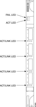
G1000-4 series Ethernet card faceplates have two card-level LEDs and a bicolored LED next to each port (Figure 9-4).
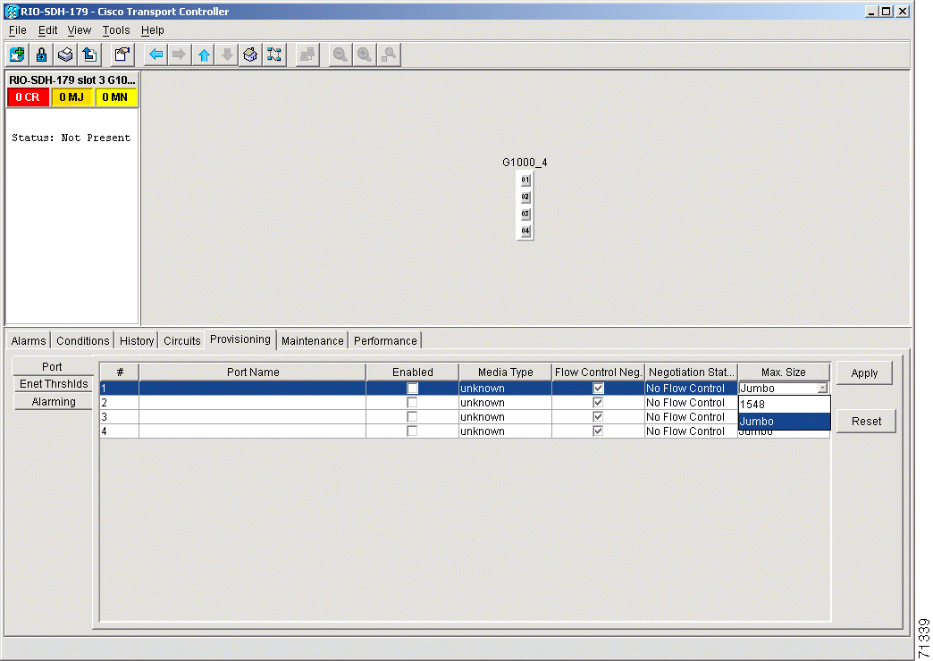
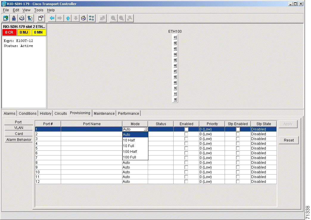
This section explains how to provision Ethernet ports on a G1000-4 card. Most provisioning requires filling in two fields: Enabled and Flow Control Negotiation. You can also configure the maximum frame size permitted, either Jumbo or 1548 bytes.
Media Type indicates the type of GBIC installed. For more information on GBICs for the G1000-4 card, see the "G1000-4 Gigabit Interface Converters" section. The Negotiation Status column displays the result of the most-recent auto-negotiation. The type of flow control that was negotiated will be displayed.
|
Note You can only provision flow control on the G1000-4 by enabling auto-negotiation. If the attached device does not support auto-negotiation or is not correctly configured to support the G1000-4's asymmetric flow control, flow control is ignored. |
Step 2 Click the Provisioning > Port tabs.
Figure 9-5 shows the Provisioning tab with the Port subtab selected.
Step 3 If you want to label the port, double-click the Port Name heading. Click anywhere else on the screen to save the change.
Step 4 Click the Enabled checkbox(s) to activate the corresponding Ethernet port(s).
Step 5 To disable/enable flow control negotiation, click the Flow Control Neg. checkbox.
Flow control negotiation is enabled by default.
|
Note Flow control is enabled only when the attached device is set for auto-negotiation. If auto-negotiation has been provisioned on the attached device but the negotiation status indicates no flow control, check the auto-negotiation settings on the attached device for interoperation with the asymmetric flow control capability of the G1000-4. |
Step 6 To permit the acceptance of jumbo size Ethernet frames, click the Max. Size column to reveal the pull-down menu and select Jumbo.
The maximum accepted frame size is set to Jumbo by default.
Step 7 Click Apply.
|
Note Reprovisioning an Ethernet port on the G1000-4 card does not reset the Ethernet statistics for that port. See the "Statistics Window" section for information about clearing the statistics for the G1000-4 port. Reprovisioning an Ethernet port on the E-series Ethernet cards resets the Ethernet statistics for that port. |
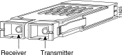
Gigabit interface converters (GBICs) are hot-swappable input/output devices that plug into a Gigabit Ethernet card to link the port with the fiber-optic network. Figure 9-6 shows a GBIC. The type of GBIC determines the maximum distance that the Ethernet traffic will travel from the card to the next network device.
The G1000-4 card supports three types of standard Cisco GBICs; SX, LX and ZX.
1000BaseSX operates on multi-mode fiber optic link spans of up to 550 m in length. 1000BaseLX operates on single-mode fiber optic links of up to 10 km in length. 1000BaseZX operates on single-mode fiber optic link spans of up to 70 km in length, and link spans of up to 100 km are possible using premium single mode fiber or dispersion shifted single mode fiber.
Table 9-1 shows the available GBICs for the G1000-4 card.
|
Caution Use only GBICs certified for use in the ONS 15454 SDH G1000-4 card (Cisco product numbers 15454-GBIC-SX, 15454-GBIC-LX and 15454-GBIC-ZX). |
For GBIC installation and cabling instructions, see the "Install Gigabit Interface Converters" section.
The E series cards incorporate layer 2 switching, while the G series card is a straight mapper card. E series cards support VLAN, IEEE 802.1Q, spanning tree, and IEEE 802.1D. An ONS 15454 SDH holds a maximum of ten Ethernet cards, and you can insert Ethernet cards in any multipurpose slot. For card specifications, see the Card Reference chapter in the Cisco ONS 15454 SDH Troubleshooting and Maintenance Guide.
E100T-G cards provide twelve switched, IEEE 802.3-compliant 10/100 Base-T Ethernet ports. The ports detect the speed of an attached device by auto-negotiation and automatically connect at the appropriate speed and duplex mode, either half or full duplex, and determine whether to enable or disable flow control.
E1000-2-G cards provides two switched, IEEE 802.3-compliant Gigabit Ethernet (1000 Mbps) ports that support full duplex operation.
E series Ethernet card faceplates have three card-level LEDs and a pair of port-level LEDs next to each port. The SF LED is inactive.
Table 9-2 E Series Card-Level LEDS
|
For detailed specifications of the Ethernet cards, refer to the Cisco ONS 15454 SDH Troubleshooting and Maintenance Guide.
This section explains how to provision Ethernet ports on an E series Ethernet card. Most provisioning requires filling in two fields: Enabled and Mode. However, you can also map incoming traffic to a low priority or a high priority queue using the Priority column, and you can disable spanning tree with the Stp Enabled column. For more information about spanning tree, see the "E Series Spanning Tree (IEEE 802.1D)" section. The Status column displays information about the port's current operating mode, and the Stp State column provides the current spanning tree status.
Step 2 Click the Provisioning > Port tabs (Figure 9-7).
Step 3 From the Port screen, choose the appropriate mode for each Ethernet port.
Valid choices for the E100T-G card:
Valid choices for the E1000-2-G card:
|
Note Both 1000 Full and Auto mode set the E1000-2-G port to the 1000 Mbps and Full duplex operating mode; however, flow control is disabled when 1000 Full is selected. Choosing Auto mode enables the E1000-2-G card to auto-negotiate flow control. Flow control is a mechanism that prevents network congestion by ensuring that transmitting devices do not overwhelm receiving devices with data. The E1000-2-G port handshakes with the connected network device to determine if that device supports flow control. |
Step 4 Click the Enabled checkbox(s) to activate the corresponding Ethernet port(s).
Step 5 Click Apply.
Your Ethernet ports are now provisioned and ready to be configured for VLAN membership.
Step 6 Repeat this procedure for all other cards that will be in the VLAN.
Gigabit interface converters (GBICs) are hot-swappable input/output devices that plug into a Gigabit Ethernet card to link the port with the fiber-optic network. The type of GBIC determines the maximum distance that the Ethernet traffic will travel from the card to the next network device.
The E1000-2-G card supports SX and LX GBICs.
1000BaseSX operates on multi-mode fiber optic link spans of up to 550 m in length. 1000BaseLX operates on single-mode fiber optic links of up to 10 km in length.
Table 9-4 shows the available GBICs.
For GBIC installation and cabling instructions, see the "Install Gigabit Interface Converters" section.
|
Caution Use only GBICs certified for use in the ONS 15454 SDH E1000-2-G card, Cisco product numbers 15454-GBIC-SX and 15454-GBIC-LX. |
|
Caution E1000-2-G cards lose traffic for approximately 30 seconds when an ONS 15454 SDH database is restored. Traffic is lost during the period of spanning tree reconvergence. The CARLOSS alarm will appear and clear during this period. |
The ONS 15454 SDH enables multicard and single-card EtherSwitch modes for E series cards. At the Ethernet card view in CTC, click the Provisioning > Card tabs to reveal the Card Mode option.
Multicard EtherSwitch provisions two or more Ethernet cards to act as a single layer 2 switch. It supports one VC4-2c circuit or two VC4 circuits. The bandwidth of the single switch formed by the Ethernet cards matches the bandwidth of the provisioned Ethernet circuit up to VC4-2c worth of bandwidth. Figure 9-8 illustrates a Multicard EtherSwitch configuration.
Single-card EtherSwitch allows each Ethernet card to remain a single switching entity within the ONS 15454 SDH shelf. This option allows a full VC4-4c worth of bandwidth between two Ethernet circuit points. Figure 9-9 illustrates a single-card EtherSwitch configuration.
Four scenarios exist for provisioning maximum single-card EtherSwitch bandwidth:
|
Note When configuring scenario 3, the VC4-2c must be provisioned before either of the VC4 circuits. |
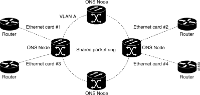
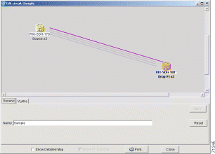
Ethernet circuits can link ONS nodes through point-to-point, shared packet ring, or hub and spoke configurations. Two nodes usually connect with a point-to-point configuration. More than two nodes usually connect with a shared packet ring configuration or a hub and spoke configuration. This section includes procedures for creating these configurations and also explains how to create Ethernet manual cross-connects. Ethernet manual cross-connects allow you to cross connect individual Ethernet circuits to an STM channel on the ONS 15454 optical interface and also to bridge non-ONS SDH network segments.
|
Note When making a VC4-4c Ethernet circuit, Ethernet cards must be configured as Single-card EtherSwitch. Multicard mode does not support VC4-4c Ethernet circuits. |
The ONS 15454 SDH can set up a point-to-point (straight) Ethernet circuit as Single-card or Multicard. Multicard EtherSwitch limits bandwidth to VC4-2c of bandwidth between two Ethernet circuit points, but allows adding nodes and cards and making a shared packet ring. Single-card EtherSwitch allows a full VC4-4c of bandwidth between two Ethernet circuit points.
Step 2 Double-click one of the Ethernet cards that will carry the circuit.
Step 3 Click the Provisioning > Card tabs.
Step 4 If you are building a Multicard Etherswitch point-to-point circuit:
a. Under Card Mode, verify that Multi-card EtherSwitch Group is checked.
b. If Multi-card EtherSwitch Group is not checked, check it and click Apply.
c. Repeat Steps 2 - 4 for all other Ethernet cards in the ONS 15454 SDH that will carry the circuit.
If you are building a Single-card Etherswitch circuit:
d. Under Card Mode, verify that Single-card EtherSwitch is checked.
e. If Single-card EtherSwitch is not checked, check it and click Apply.
Step 5 Navigate to the other ONS 15454 SDH Ethernet circuit endpoint.
Step 6 Repeat Steps 2 - 5.
Step 7 Click the Circuits tab and click Create.
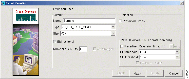
The Circuit Creation (Circuit Attributes) dialog box opens.
Step 8 In the Name field, type a name for the circuit.
Step 9 From the Type pull-down menu, choose VC_HO_PATH_CIRCUIT.
Step 10 Choose the size of the circuit from the Size pull-down menu.
The valid circuit sizes for an Ethernet Multicard circuit are VC4 and VC4-2c.
The valid circuit sizes for an Ethernet Single-card circuit are VC4, VC4-2c and VC4-4c.
Step 11 Verify that the Bidirectional checkbox is checked and click Next.
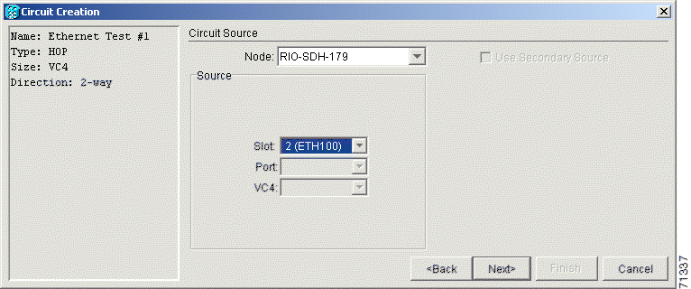
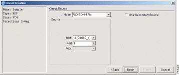
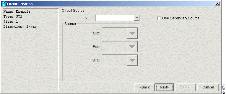
The Circuit Creation (Circuit Source) dialog box opens (Figure 9-12).
Step 12 Choose the circuit source from the Node menu. Either end node can be the circuit source.
Step 13 If you are building a Multicard EtherSwitch circuit, choose Ethergroup from the Slot menu and click Next.
Step 14 If you are building a Single-card EtherSwitch circuit, from the Slot menu choose the Ethernet card where you enabled the Single-card Etherswitch and click Next.
The Circuit Creation (Destination) dialog box opens.
Step 15 Choose the circuit destination from the Node menu, (in this example, Node 2). Choose the node that is not the source.
Step 16 If you are building a Multicard EtherSwitch circuit choose Ethergroup from the Slot menu and click Next.
Step 17 If you are building a Single-card EtherSwitch circuit, from the Slot menu choose the Ethernet card for which you enabled the Single-card Etherswitch and click Next.
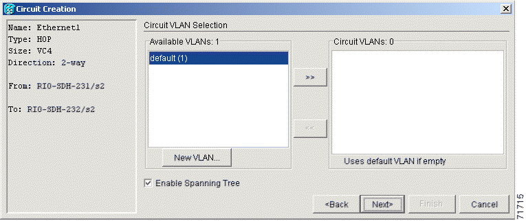
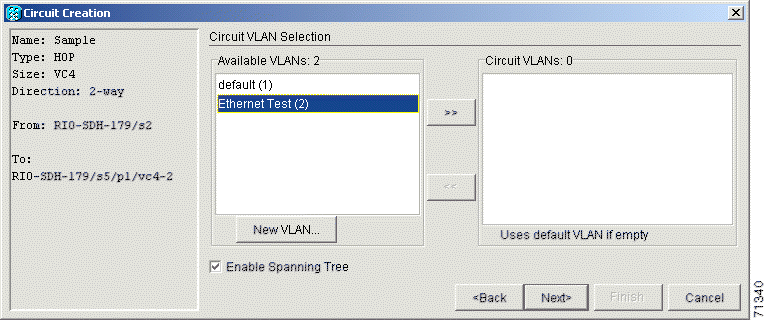
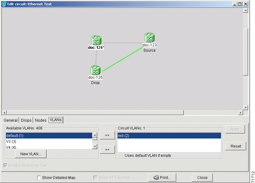
The Circuit Creation (Circuit VLAN Selection) dialog box opens.
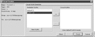
Step 18 Create the VLAN:
|
Note The VLAN ID should be the next available number between 2 and 4093 that is not already assigned to an existing VLAN. Each ONS 15454 SDH network supports a maximum of 509 user-provisionable VLANs. |
e. Highlight the VLAN name and click the >> tab to move the available VLAN(s) to the Circuit VLANs column.
Step 19 If you are building a Single-card EtherSwitch circuit and wish to disable spanning tree protection on this circuit, uncheck the Enable Spanning Tree checkbox and click OK on the Disabling Spanning Tree dialog that appears.
|
Caution Disabling spanning tree protection increases the likelihood of logic loops on an Ethernet network. |
|
Note The Enable Spanning Tree box is "sticky." It will remain in the same state, checked or unchecked, for the creation of the next Single-card point-to-point Ethernet circuit. |
|
Note Users can disable or enable spanning tree protection on a circuit-by-circuit basis only for single-card point-to-point Ethernet circuits. Other E-series Ethernet configurations disable or enable spanning tree on a port-by-port basis at the card view of CTC under the Provisioning tab. |
Step 20 Click Next.
The Circuit Creation (Circuit Routing Preferences) dialog box opens.
Step 21 Confirm that the following information about the point-to-point circuit is correct:
Step 22 Click Finish.
Step 23 You now need to provision the Ethernet ports and assign ports to VLANs. For port provisioning instructions, see the "Provision E Series Ethernet Ports" procedure. For assigning ports to VLANs, see the "Provision Ethernet Ports for VLAN Membership" procedure. For information about manually provisioning circuits, see the "E Series Ethernet Manual Cross-Connects" procedure.
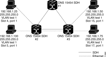
This section provides steps for creating a shared packet ring (Figure 9-14). Your network architecture may differ from the example.
Step 2 Double-click one of the Ethernet cards that will carry the circuit.
Step 3 Click the Provisioning > Card tabs.
Step 4 Under Card Mode, verify that Multi-card EtherSwitch Group is checked.
Step 5 If Multi-card EtherSwitch Group is not checked, check it and click Apply.
Step 6 Display the node view.
Step 7 Repeat Steps 2 - 6 for all other Ethernet cards in the ONS 15454 SDH that will carry the shared packet ring.
Step 8 Navigate to the other ONS 15454 SDH endpoint.
Step 9 Repeat Steps 2 - 7.
Step 10 Click the Circuits tab and click Create.
The Circuit Creation (Circuit Attributes) dialog box opens.
Step 11 In the Name field, type a name for the circuit.
Step 12 From the Type pull-down menu, choose VC_HO_PATH_CIRCUIT.
Step 13 From the Size pull-down menu, choose the size of the circuit.
For shared packet ring Ethernet, valid circuit sizes are VC4 or VC4-2c.
Step 14 Verify that the Bidirectional checkbox is checked.
|
Note If you are building a shared packet ring configuration, you must manually provision the circuits. |
Step 15 Click Next.
The Circuit Creation (Circuit Source) dialog box opens.
Step 16 From the Node menu, choose the circuit source.
Any shared packet ring node can serve as the circuit source.
Step 17 Choose Ethergroup from the Slot menu and click Next.
The Circuit Creation (Circuit Destination) dialog box opens.
Step 18 Choose the circuit destination from the Node menu.
Step 19 Except for the source node, any shared packet ring node can serve as the circuit destination.
Step 20 Choose Ethergroup from the Slot menu and click Next.
The Circuit Creation (Circuit VLAN Selection) dialog box opens.
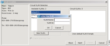
Step 21 Create the VLAN:
The Circuit Creation (Define New VLAN) dialog box opens (Figure 9-15).
This VLAN ID number must be unique. It is usually the next available number not already assigned to an existing VLAN (between 2 and 4093). Each ONS 15454 SDH network supports a maximum of 509 user-provisionable VLANs.
e. Highlight the VLAN name and click the >> tab to move the VLAN(s) from the Available VLANs column to the Circuit VLANs column (Figure 9-16).
By moving the VLAN from the Available VLANs column to the Circuit VLANs column, all the VLAN traffic is forced to use the shared packet ring circuit you created.
Step 22 Click Next.
Step 23 Uncheck the Route Automatically checkbox and click Next.
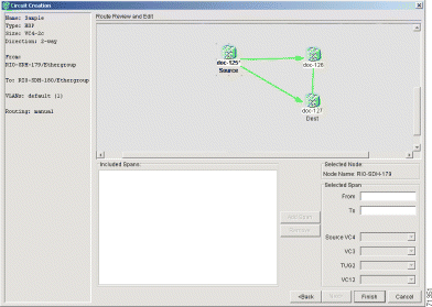
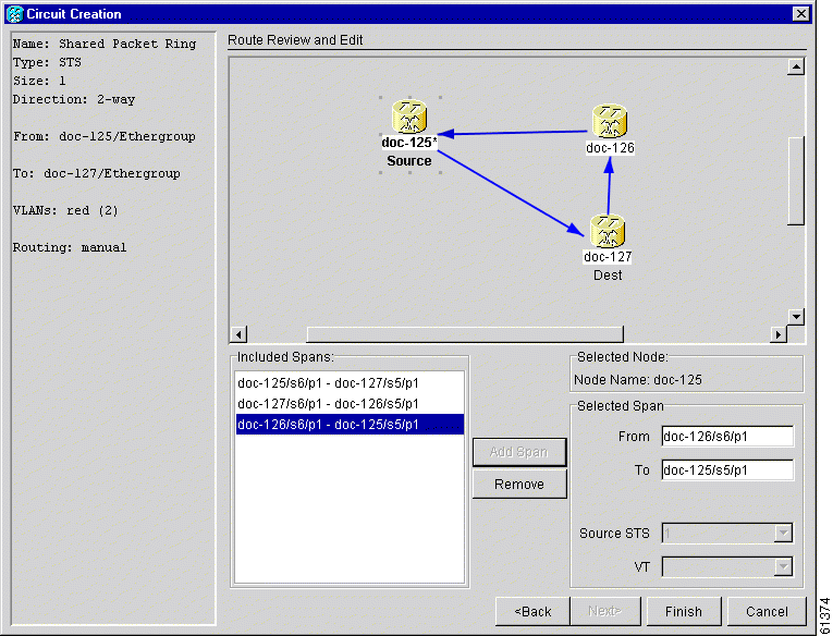
Step 24 Click either span (green arrow) leading from the source node. (Figure 9-17)
Step 25 Click Add Span.
The span turns blue and adds the span to the Included Spans field.
Step 26 Click the node at the end of the blue span.
Step 27 Click the green span leading to the next node.
Step 28 Click Add Span.
Step 29 Repeat Steps 24 - 27 for every node remaining in the ring. Figure 9-18 shows the Circuit Path Selection dialog box with all the spans selected.
Step 30 Verify that the new circuit is correctly configured.
|
Note If the circuit information is not correct, click the Back button and repeat the procedure with the correct information. You can also click Finish, highlight the completed circuit, click the Delete button and start the procedure from the beginning. |
Step 31 Click Finish.
Step 32 You now need to provision the Ethernet ports and assign ports to VLANs. For port provisioning instructions, see the "Provision E Series Ethernet Ports" procedure. For assigning ports to VLANs, see the "Provision Ethernet Ports for VLAN Membership" procedure.
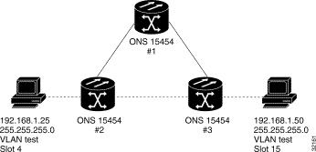
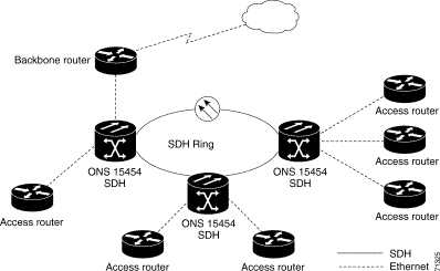
This section provides steps for creating a hub and spoke Ethernet circuit configuration. The hub and spoke configuration connects point-to-point circuits (the spokes) to an aggregation point (the hub). In many cases, the hub links to a high-speed connection and the spokes are Ethernet cards. Figure 9-19 illustrates a sample hub and spoke ring. Your network architecture may differ from the example.
Step 2 Double-click the Ethernet card that will create the circuit.
Step 3 Click the Provisioning > Card tabs.
Step 4 Under Card Mode, check the Single-card EtherSwitch checkbox.
If Single-card EtherSwitch is not checked, check it and click Apply.
Step 5 Navigate to the other ONS 15454 SDH endpoint and repeat Steps 2 - 4.
Step 6 Display the node view or network view.
Step 7 Click the Circuits tab and click Create.
The Circuit Creation (Circuit Attributes) dialog box opens.
Step 8 In the Name field, type a name for the circuit.
Step 9 From the Type pull-down menu, choose VC_HO_PATH_CIRCUIT.
Step 10 Choose the size of the circuit from the Size pull-down menu.
Step 11 Verify that the Bidirectional checkbox is checked and click Next.
The Circuit Creation (Circuit Source) dialog box opens.
Step 12 From the Node menu, choose the circuit source.
Either end node can be the circuit source.
Step 13 From the Slot menu, choose the Ethernet card where you enabled the single-card EtherSwitch and click Next.
The Circuit Creation (Circuit Destination) dialog box opens.
Step 14 Choose the circuit destination from the Node menu.
Choose the node that is not the source.
Step 15 From the Slot menu, choose the Ethernet card where you enabled the single-card EtherSwitch and click Next.
The Circuit Creation (Circuit VLAN Selection) dialog box opens (Figure 9-12).
Step 16 Create the VLAN:
The Circuit Creation (Define New VLAN) dialog box opens (Figure 9-15).
This should be the next available number (between 2 and 4093) not already assigned to an existing VLAN. Each ONS 15454 SDH network supports a maximum of 509 user-provisionable VLANs.
e. Highlight the VLAN name and click the >> tab to move the VLAN(s) from the Available VLANs column to the Circuit VLANs column (Figure 9-16).
Step 17 Click Next.
The Circuit Creation (Circuit Routing Preferences) dialog box opens.
Step 18 Confirm that the following information about the point-to-point circuit is correct:
|
Note If the circuit information is not correct, click the Back button and repeat the procedure with the correct information. You can also click Finish, highlight the completed circuit, click the Delete button and start the procedure from the beginning. |
Step 19 Click Finish.
You must now provision the second circuit and attach it to the already-created VLAN.
Step 20 Log into the ONS 15454 SDH Ethernet circuit endpoint for the second circuit.
Step 21 Double-click the Ethernet card that will create the circuit. The CTC card view displays.
Step 22 Click the Provisioning > Card tabs.
Step 23 Under Card Mode, check Single-card EtherSwitch.
If the Single-card EtherSwitch checkbox is not checked, check it and click Apply.
Step 24 Log into the other ONS 15454 SDH endpoint for the second circuit and repeat Steps 21 - 23.
Step 25 Display the CTC node view.
Step 26 Click the Circuits tab and click Create.
Step 27 Choose VC_HO_PATH_CIRCUIT from the Type pull-down menu.
Step 28 Choose the size of the circuit from the Size pull-down menu.
Step 29 Verify that the Bidirectional checkbox is checked and click Next.
Step 30 Choose the circuit source from the Node menu and click Next.
Either end node can be the circuit source.
Step 31 Choose the circuit destination from the Node menu.
Choose the node that is not the source.
Step 32 From the Slot menu, choose the Ethernet card where you enabled the single-card EtherSwitch and click Next.
The Circuit Creation (Circuit VLAN Selection) dialog box is displayed.
Step 33 Highlight the VLAN that you created for the first circuit and click the >> tab to move the VLAN(s) from the Available VLANs column to the Selected VLANs column.
Step 34 Click Next and click Finish.
Step 35 You now need to provision the Ethernet ports and assign ports to VLANs. For port provisioning instructions, see the "Provision E Series Ethernet Ports" procedure. For assigning ports to VLANs, see the "Provision Ethernet Ports for VLAN Membership" procedure.
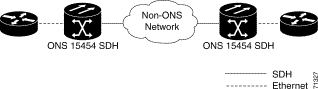
ONS 15454 SDHs require end-to-end CTC visibility between nodes for normal provisioning of Ethernet circuits. When other vendors' equipment sits between ONS 15454 SDHs, OSI/TARP- based equipment does not allow tunneling of the ONS 15454 SDH TCP/IP-based DCC. To circumvent this lack of continuous DCC, the Ethernet circuit must be manually cross connected to an VC-4 channel riding through the non-ONS network. This allows an Ethernet circuit to run from ONS node to ONS node utilizing the non-ONS network.
|
Note Provisioning manual cross-connects for Multicard Etherswitch circuits is a separate procedure from provisioning manual cross-connects for Single-card Etherswitch circuits. Both procedures are listed below. |
Step 2 Double-click one of the Ethernet cards that will carry the circuit.
Step 3 Click the Provisioning > Card tabs.
Step 4 Under Card Mode, verify that Single-card EtherSwitch is checked.
If the Single-card EtherSwitch is not checked, check it and click Apply.
Step 5 Display the node view.
Step 6 Click the Circuits tab and click Create.
The Circuit Creation (Circuit Attributes) dialog box opens (Figure 9-21).
Step 7 In the Name field, type a name for the circuit.
Step 8 From the Type pull-down menu, choose VC_HO_PATH_CIRCUIT.
Step 9 Choose the size of the circuit from the Size pull-down menu.
The valid circuit sizes for an Ethernet Multicard circuit are VC4 and VC4-2c.
Step 10 Verify that the Bidirectional checkbox is checked and click Next.
The Circuit Creation (Circuit Source) dialog box opens.
Step 11 From the Node menu, choose the current node as the circuit source.
Step 12 From the Slot menu, choose the Ethernet card that will carry the circuit and click Next.
The Circuit Creation (Circuit Destination) dialog box opens.
Step 13 From the Node menu, choose the current node as the circuit destination.
Step 14 From the Slot menu, choose the optical card that will carry the circuit.
Step 15 Choose the VC4 that will carry the circuit from the VC4 menu and click Next.
The Circuit Creation (Circuit VLAN Selection) dialog box opens.
Step 16 Create the VLAN:
The Circuit Creation (Define New VLAN) dialog box opens.
The VLAN ID should be the next available number (between 2 and 4093) that is not already assigned to an existing VLAN. Each ONS 15454 SDH network supports a maximum of 509 user-provisionable VLANs.
e. Highlight the VLAN name and click the arrow >> tab to move the VLAN(s) from the Available VLANs column to the Circuit VLANs column (Figure 9-22).
Step 17 Click Next.
The Circuit Creation (Circuit Routing Preferences) dialog box opens.
Step 18 Confirm that the following information is correct:
|
Note If the circuit information is not correct use the Back button, then redo the procedure with the correct information. You can also click Finish, highlight the completed circuit, click the Delete button and start the procedure from the beginning. |
Step 19 Click Finish.
Step 20 You now need to provision the Ethernet ports and assign ports to VLANs. For port provisioning instructions, see the "Provision E Series Ethernet Ports" procedure. For assigning ports to VLANs, see the "Provision Ethernet Ports for VLAN Membership" procedure.
Step 21 After assigning the ports to the VLANs, repeat Steps 1 - 19 at the second ONS 15454 SDH Ethernet manual cross-connect endpoint.
|
Note The appropriate VC-4 circuit must exist in the non-ONS equipment to connect the two VC-4 circuits from the ONS 15454 SDH Ethernet manual cross-connect endpoints. |
|
Caution If a CARLOSS alarm repeatedly appears and clears on an Ethernet manual cross connect, the two Ethernet circuits may have a circuit-size mismatch. For example, a circuit size of VC4-2c was configured on the first ONS 15454 SDH and circuit size of VC4 was configured on the second ONS 15454 SDH. To troubleshoot this occurrence of the CARLOSS alarm, refer to the CARLOSS alarm troubleshooting procedure in the Alarm Troubleshooting chapter of the Cisco ONS 15454 SDH Troubleshooting and Maintenance Guide. |
Step 2 Double-click one of the Ethernet cards that will carry the circuit.
Step 3 Click the Provisioning > Card tabs.
Step 4 Under Card Mode, verify that Multi-card EtherSwitch Group is checked.
If the Multicard-card EtherSwitch Group is not checked, check it and click Apply.
Step 5 Display the node view.
Step 6 Repeat Steps 2 - 5 for any other Ethernet cards in the ONS 15454 SDH that will carry the circuit.
Step 7 Click the Circuits tab and click Create.
The Circuit Creation (Circuit Attributes) dialog box opens (Figure 9-23).
Step 8 In the Name field, type a name for the circuit.
Step 9 From the Type pull-down menu, choose VC_HO_PATH_CIRCUIT.
Step 10 Choose the size of the circuit from the Size pull-down menu.
The valid circuit sizes for an Ethernet Multicard circuit are VC4 and VC4-2c.
Step 11 Verify that the Bidirectional checkbox is checked and click Next.
The Circuit Creation (Circuit Source) dialog box opens.
Step 12 From the Node menu, choose the current node as the circuit source.
Step 13 Choose Ethergroup from the Slot menu and click Next.
The Circuit Creation (Circuit Destination) dialog box opens.
Step 14 From the Node menu, choose the current node as the circuit destination.
Step 15 Choose the Ethernet card that will carry the circuit from the Slot menu and click Next.
The Circuit Creation (Circuit VLAN Selection) dialog box opens (Figure 9-16).
Step 16 Create the VLAN:
The Circuit Creation (Define New VLAN) dialog box opens (Figure 9-15).
The VLAN ID should be the next available number (between 2 and 4093) that is not already assigned to an existing VLAN. Each ONS 15454 SDH network supports a maximum of 509 user-provisionable VLANs.
e. Highlight the VLAN name and click the arrow >> tab to move the VLAN(s) from the Available VLANs column to the Circuit VLANs column (Figure 9-24).
Step 17 Click Next.
The Circuit Creation (Circuit Routing Preferences) dialog box opens.
Step 18 Confirm that the following information is correct:
|
Note If the circuit information is not correct use the Back button, then redo the procedure with the correct information. You can also click Finish, highlight the completed circuit, click the Delete button and start the procedure from the beginning. |
Step 19 Click Finish.
You now need to provision the Ethernet ports and assign ports to VLANs. For port provisioning instructions, see the "Provision E Series Ethernet Ports" procedure. For assigning ports to VLANs, see the "Provision Ethernet Ports for VLAN Membership" procedure. Return to the following step after assigning the ports to VLANs.
Step 20 Highlight the circuit and click Edit.
The Edit Circuit dialog box opens.
Step 21 Click Drops and click Create.
The Define New Drop dialog box opens.
Step 22 From the Slot menu, choose the optical card that links the ONS 15454 SDH to the non-ONS equipment.
Step 23 From the Port menu, choose the appropriate port.
Step 24 Choose the VC4 that will carry the circuit from the VC4 menu and click Next. From the VC4 menu, choose the VC4 that matches the VC4 of the connecting non-ONS equipment.
Step 25 Click OK.
The Edit Circuit dialog box opens.
Step 26 Confirm the circuit information that displays in the Circuit Information dialog box and click Close.
Step 27 Repeat Steps 1 - 26 at the second ONS 15454 SDH Ethernet manual cross-connect endpoint.
|
Note The appropriate VC-4 circuit must exist in the non-ONS equipment to connect the two ONS 15454 SDH Ethernet manual cross-connect endpoints. |
|
Caution If a CARLOSS alarm repeatedly appears and clears on an Ethernet manual cross connect, the two Ethernet circuits may have a circuit-size mismatch. For example, a circuit size of VC4-2c was configured on the first ONS 15454 SDH and circuit size of VC4 was configured on the second ONS 15454 SDH. To troubleshoot this occurrence of the CARLOSS alarm, refer to the CARLOSS alarm troubleshooting procedure in the Alarm Troubleshooting chapter of the Cisco ONS 15454 SDH Troubleshooting and Maintenance Guide. |
This section explains how to provision G1000-4 point-to-point circuits and Ethernet manual cross-connects. Ethernet manual cross-connects allow you to cross connect individual Ethernet circuits to an VC-4 channel on the ONS 15454 SDH optical interface and also to bridge non-ONS SDH network segments.
G1000-4 cards support point-to-point circuit configuration. Provisionable circuit sizes are VC4, VC4-2c, VC4-3c, VC4-4c, VC4-8c and VC4-16c. Each Ethernet port maps to a uniqueVC4 circuit on the SDH side of the G1000-4.
The G1000-4 supports any combination of up to four circuits from the list of valid circuit sizes, however the circuit sizes can add up to no more than VC4-16c. Due to hardware constraints, this card imposes additional restrictions on the combinations of circuits that can be dropped onto a G1000-4 card. These restrictions are transparently enforced by the ONS 15454 SDH, and you do not need to keep track of restricted circuit combinations.
The restriction occurs when a single VC4-8c is dropped on a card. In this instance, the remaining circuits on that card can be another single VC4-8c or any combination of circuits of VC4-4c size or less that add up to no more than VC4-4c (i.e. a total of VC4-16c on the card).
No circuit restrictions are present, if VC4-8c circuits are not being dropped on the card. The full VC4-16c bandwidth can be used (for example using either a single VC4-16c or four VC4-4c circuits).
|
Note Since the restrictions only apply when VC4-8c are involved but do not apply to two VC4-8c circuits on a card, you can easily minimize the impact of these restrictions. Group the VC4-8c circuits together on a card separate from circuits of other sizes. The grouped circuits can be dropped on other G1000-4 cards on the ONS 15454 SDH. |
|
Note All SDH side VC4 circuits must be contiguous. |
|
Caution G1000-4 circuits connect with STM-N cards or other G1000-4 cards. G1000-4 cards do not connect with E-series Ethernet cards. |
Step 2 In CTC node view, click the Circuits tab and click Create.
The Circuit Creation (Circuit Attributes) dialog box opens. (Figure 9-26)
Step 3 In the Name field, type a name for the circuit.
Step 4 From the Type pull-down menu, choose VC_HO_PATH_CIRCUIT.
Step 5 Choose the size of the circuit from the Size pull-down menu.
The valid circuit sizes for a G1000-4 circuit are VC4, VC4-2c, VC4-3c, VC4-4c, VC4-8c and VC4-16c.
Step 6 Verify that the Bidirectional checkbox is checked and click Next.
|
Note Users can ignore the Number of Circuits box and the Protected Drops box. |
|
Caution If you are provisioning a G1000-4 circuit on a path protection do not check the Switch on PDI-P box. Checking the Switch on PDI-P box may cause unnecessary path protection protection switches. |
The Circuit Creation (Circuit Source) dialog box opens (Figure 9-27).
Step 7 Choose the circuit source node from the Node menu. Either end node can be the circuit source.
Step 8 From the Slot menu choose the slot containing the G1000-4 card that you will use for one end of the point-to-point circuit.
Step 9 From the Port menu choose a port.
Step 10 Click Next.
The Circuit Creation (Destination) dialog box opens.
Step 11 Choose the circuit destination from the Node menu.
Step 12 From the Slot menu choose the slot that holds the G1000-4 card that you will use for the other end of the point-to-point circuit.
Step 13 From the Port menu choose a port.
Step 14 Click Next.
The Circuit Creation (Circuit Routing Preferences) dialog box opens.
Step 15 Confirm that the following information about the point-to-point circuit is correct:
Step 16 Click Finish.
Step 17 If you have not already provisioned the Ethernet card, follow the "Provision G1000-4 Ethernet Ports" procedure.
|
Note To change the capacity of a G1000-4 point-to-point circuit, you must delete the original circuit and reprovision a new larger circuit. |
ONS 15454 SDHs require end-to-end CTC visibility between nodes for normal provisioning of Ethernet circuits. When other vendors' equipment sits between ONS 15454 SDHs, OSI/TARP-based equipment does not allow tunneling of the ONS 15454 SDH TCP/IP-based DCC. To circumvent a lack of continuous DCC, the Ethernet circuit must be manually cross connected to a VC-4 channel riding through the non-ONS network. This allows an Ethernet circuit to run from ONS node to ONS node while utilizing the non-ONS network.
|
Note In this chapter, "cross-connect" and "circuit" have the following meanings: Cross-connect refers to the connections that occur within a single ONS 15454 SDH to allow a circuit to enter and exit an ONS 15454 SDH. Circuit refers to the series of connections from a traffic source (where traffic enters the ONS 15454 SDH network) to the drop or destination (where traffic exits an ONS 15454 SDH network). |
Step 2 Click the Circuits tab and click Create.
Step 3 The Circuit Creation (Circuit Attributes) dialog box opens.
Step 4 In the Name field, type a name for the circuit.
Step 5 From the Type pull-down menu, choose VC_HO_PATH_CIRCUIT.
Step 6 Choose the size of the circuit from the Size pull-down menu.
The valid circuit sizes for a G1000-4 circuit are VC4, VC4-2c, VC4-3c, VC4-4c, VC4-8c and VC4-16c.
Step 7 Verify that the Bidirectional checkbox is checked and click Next.
The Circuit Creation (Circuit Source) dialog box opens (Figure 9-29).
Step 8 Choose the circuit source node from the Node menu.
Step 9 From the Slot menu choose the slot containing the Ethernet card.
Step 10 From the Port menu choose a port.
Step 11 Click Next.
The Circuit Creation (Destination) dialog box opens.
Step 12 From the Node menu, choose the current node as the circuit destination.
Step 13 From the Slot menu, choose the optical card that will carry the circuit.
Step 14 Choose the VC4 that will carry the circuit from the VC4 menu and click Next.
|
Note For Ethernet manual cross-connects, the same ONS 15454 SDH serves as both source and destination. |
Step 15 Confirm that the following information is correct:
|
Note If the circuit information is not correct use the Back button, then redo the procedure with the correct information. You can also click Finish, highlight the completed circuit, click the Delete button and start the procedure from the beginning. |
Step 16 Click Finish.
Step 17 You now need to provision the Ethernet ports. For port provisioning instructions, see the "Provision G1000-4 Ethernet Ports" procedure.
Step 18 To complete the procedure, repeat Steps 1 - 16 at the second ONS 15454 SDH.
|
Note The appropriate STM circuit must exist in the non-ONS equipment to connect the two STMs from the ONS 15454 SDH Ethernet manual cross-connect endpoints. |
|
Caution If a CARLOSS alarm repeatedly appears and clears on an Ethernet manual cross connect, the two Ethernet circuits may have a circuit-size mismatch. For example, a circuit size of VC4-2c was configured on the first ONS 15454 SDH and circuit size of VC4 was configured on the second ONS 15454 SDH. To troubleshoot this occurrence of the CARLOSS alarm, refer to the CARLOSS alarm troubleshooting procedure in the Alarm Troubleshooting chapter of the Cisco ONS 15454 SDH Troubleshooting and Maintenance Guide. |
Users can provision up to 509 VLANs with the CTC software. Specific sets of ports define the broadcast domain for the ONS 15454 SDH. The definition of VLAN ports includes all Ethernet and packet-switched SDH port types. All VLAN IP address discovery, flooding, and forwarding is limited to these ports.
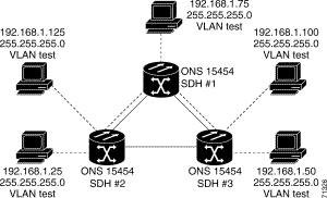
The ONS 15454 SDH 802.1Q-based VLAN mechanism provides logical isolation of subscriber LAN traffic over a common SDH transport infrastructure. Each subscriber has an Ethernet port at each site, and each subscriber is assigned to a VLAN. Although the subscriber's VLAN data flows over shared circuits, the service appears to the subscriber as a private data transport.
IEEE 802.1Q allows the same physical port to host multiple 802.1Q VLANs. Each 802.1Q VLAN represents a different logical network.
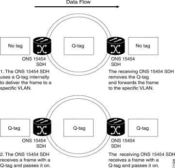
The ONS 15454 SDH works with Ethernet devices that support IEEE 802.1Q and those that do not support IEEE 802.1Q. If a device attached to an ONS 15454 SDH Ethernet port does not support IEEE 802.1Q, the ONS 15454 SDH only uses Q-tags internally. The ONS 15454 SDH associates these Q-tags with specific ports.
With Ethernet devices that do not support IEEE 802.1Q, the ONS 15454 SDH takes non-tagged Ethernet frames that enter the ONS network and uses a Q-tag to assign the packet to the VLAN associated with the ONS network's ingress port. The receiving ONS node removes the Q-tag when the frame leaves the ONS network (to prevent older Ethernet equipment from incorrectly identifying the 8021.Q packet as an illegal frame). The ingress and egress ports on the ONS network must be set to Untag for the process to occur. Untag is the default setting for ONS ports. Example #1 in Figure 9-30 illustrates Q-tag use only within an ONS network.
With Ethernet devices that support IEEE 802.1Q, the ONS 15454 SDH uses the Q-tag attached by the external Ethernet devices. Packets enter the ONS network with an existing Q-tag; the ONS 15454 SDH uses this same Q-tag to forward the packet within the ONS network and leaves the Q-tag attached when the packet leaves the ONS network. Set both entry and egress ports on the ONS network to Tagged for this process to occur. Example #2 in Figure 9-30 illustrates the handling of packets that both enter and exit the ONS network with a Q-tag.
To set ports to Tagged and Untag, see the "Provision Ethernet Ports for VLAN Membership" procedure.
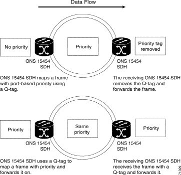
Networks without priority queuing handle all packets on a first-in-first-out basis. Priority queuing reduces the impact of network congestion by mapping Ethernet traffic to different priority levels. The ONS 15454 SDH supports priority queuing. The ONS 15454 SDH takes the eight priorities specified in IEEE 802.1Q and maps them to two queues (Table 9-5). Q-tags carry priority queuing information through the network.
The ONS 15454 SDH uses a "leaky bucket" algorithm to establish a weighted priority (not a strict priority). A weighted priority gives high-priority packets greater access to bandwidth, but does not totally preempt low-priority packets. During periods of network congestion, roughly 70% of bandwidth goes to the high-priority queue and the remaining 30% goes to the low-priority queue. A network that is too congested will drop packets.
This section explains how to provision Ethernet ports for VLAN membership. For initial port provisioning (prior to provisioning VLAN membership) see the "E Series Port Provisioning" section.
|
Caution ONS 15454 SDHs propagate VLANs whenever a node appears on the same network view of another node regardless of whether the nodes connect through DCC. For example, if two ONS 15454 SDHs without DCC connectivity belong to the same Login Node Group, then whenever CTC gets launched from within this login node group, VLANs propagate from one to another. This happens even though the ONS 15454 SDHs do not belong to the same SDH ring. |
The ONS 15454 SDH allows you to configure the VLAN membership and Q-tag handling of individual Ethernet ports on the E-series Ethernet cards.
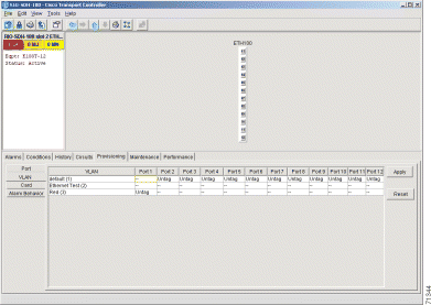
Step 2 Click the Provisioning > VLAN tabs (Figure 9-32).
Step 3 To put a port in a VLAN, click the port and choose either Tagged or Untag. Figure 9-32 shows Port 1 in the red VLAN and Port 2 through Port 12 in the default VLAN. Table 9-6 shows valid port settings.
If a port is a member of only one VLAN, go to that VLAN's row and choose Untag from the Port column. Choose -- for all the other VLAN rows in that Port column. The VLAN with Untag selected can connect to the port, but other VLANs cannot access that port.
If a port is a trunk port, it connects multiple VLANs to an external device, such as a switch, which also supports trunking. A trunk port must have tagging (802.1Q) enabled for all the VLANs that connect to that external device. Choose Tagged at all VLAN rows that need to be trunked. Choose Untag at one or more VLAN rows in the trunk port's column that do not need to be trunked, for example, the default VLAN. Each Ethernet port must attached to at least one untagged VLAN.
Step 4 After each port is in the appropriate VLAN, click Apply.
|
|
Note If Tagged is chosen, the attached external devices must recognize IEEE 802.1Q VLANs. |
|
Note Both ports on individual E1000-2-G cards cannot be members of the same VLAN. |
The ONS 15454 SDH displays the number of VLANs used by circuits and the total number of VLANs available for use. To display the number of available VLANs and the number of VLANs used by circuits, click the Circuits tab and click an existing Ethernet circuit to highlight it. Click Edit. Click the VLANs tab.
The Cisco ONS 15454 SDH operates spanning tree protocol (STP) according to IEEE 802.1D when an Ethernet card is installed. STP operates over all packet-switched ports including Ethernet and SDH ports. On Ethernet ports, STP is enabled by default but may be disabled with a check box under the Provisioning > Port tabs at the card-level view. A user can also disable or enable spanning tree on a circuit-by-circuit basis on unstitched Ethernet cards in a point-to-point configuration. However, turning off spanning tree protection on a circuit-by-circuit basis means that the ONS 15454 system is not protecting the Ethernet traffic on this circuit, and the Ethernet traffic must be protected by another mechanism in the Ethernet network. On SDH interface ports, STP activates by default and cannot be disabled.
The Ethernet card can enable STP on the Ethernet ports to allow redundant paths to the attached Ethernet equipment. STP spans cards so that both equipment and facilities are protected against failure.
STP detects and eliminates network loops. When STP detects multiple paths between any two network hosts, STP blocks ports until only one path exists between any two network hosts (Figure 9-34). The single path eliminates possible bridge loops. This is crucial for shared packet rings, which naturally include a loop.
To remove loops, STP defines a tree that spans all the switches in an extended network. STP forces certain redundant data paths into a standby (blocked) state. If one network segment in the STP becomes unreachable, the spanning-tree algorithm reconfigures the spanning-tree topology and reactivates the blocked path to reestablish the link. STP operation is transparent to end stations, which do not discriminate between connections to a single LAN segment or to a switched LAN with multiple segments. The ONS 15454 SDH supports one STP instance per circuit and a maximum of eight STP instances per ONS 15454 SDH.
|
Caution Multiple circuits with spanning tree protection enabled will incur blocking, if the circuits traverse a common card and use the same VLAN. |
The ONS 15454 SDH can operate multiple instances of STP to support VLANs in a looped topology. You can dedicate separate circuits across the SDH ring for different VLAN groups (i.e., one for private TLS services and one for Internet access). Each circuit runs its own STP to maintain VLAN connectivity in a multi-ring environment.
Step 2 Click the Provisioning > Port tabs.
Step 3 In the left-hand column, find the applicable port number and check the Stp Enabled checkbox to enable STP for that port.
Step 4 Click Apply.
Default spanning tree parameters are appropriate for most situations. Contact the Cisco Technical Assistance Center (TAC) before you change the default STP parameters. To obtain a directory of toll-free Cisco TAC telephone numbers for your country, refer to the Cisco ONS 15454 SDH Product Overview preference section.
At the node view, click the Maintenance > Etherbridge > Spanning Trees tabs to view spanning tree parameters.
Table 9-7 Spanning Tree Parameters
|
To view the spanning tree configuration, at the node view click the Provisioning > Etherbridge tabs.
The Circuit screen shows forwarding spans and blocked spans on the spanning tree map.
|
Note Green represents forwarding spans and purple represents blocked (protect) spans. If you have a packet ring configuration, at least one span should be purple. |
CTC provides Ethernet performance information, including line-level parameters, the amount of port bandwidth used, and historical Ethernet statistics. CTC also includes spanning tree information, MAC address information, and the amount of circuit bandwidth used. To view spanning tree information, see the "E Series Spanning Tree Parameters" section.
CTC provides Ethernet performance information that include line-level parameters, the amount of port bandwidth used, and historical Ethernet statistics.
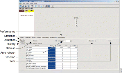
The Ethernet statistics screen lists Ethernet parameters at the line level. Display the CTC card view for the Ethernet card and click the Performance > Statistics tabs to display the screen.
Table 9-9 G1000-4 Statistics Values
|
|
Note The CTC automatically refreshes the counter values once right after a Baseline operation, so if traffic is flowing during a baseline operation, some traffic counts may immediately be observed instead of zero counts. |
|
Note The Clear button will not cause the G1000-4 card to reset. Provisioning, enabling, or disabling a G1000-4 port will not reset the statistics. |
|
Note You can apply both the Baseline and the Clear functions to a single port or all ports on the card. To apply Baseline or Clear to a single port, click the port column to highlight the port and click the Baseline or Clear button. |
Table 9-10 Ethernet Parameters
|
|
Note The HDLC errors counter should not be used to count the number of frames dropped due to HDLC errors as each frame can get fragmented into several smaller frames during HDLC error conditions and spurious HDLC frames can also generate. If these counters are incrementing at a time when there should be no SDH path problems that may indicate a problem with the quality of the SDH path. For example, an SDH protection switch causes a set of HLDC errors to generate. The actual values of these counters are less relevant than the fact they are changing. |
The Utilization subtab shows the percentage of current and past line bandwidth used by the Ethernet ports. Display the CTC card view and click the Performance and Utilization tabs to display the screen. From the Interval menu, choose a time segment interval. Valid intervals are 1 minute, 15 minutes, 1 hour, and 1 day. Press Refresh to update the data.
Line utilization is calculated with the following formula:
((inOctets + outOctets) + (inPkts + outPkts) * 20)) * 8 / 100% interval*maxBaseRate * 2.
The interval is defined in seconds. maxBaseRate is defined by raw bits/second in one direction for the Ethernet port (i.e. 1 Gbps). maxBaseRate is multiplied by 2 in the denominator to determine the raw bit rate in both directions.
|
Note Line utilization numbers express the average of ingress and egress traffic as a percentage of capacity. |
The Ethernet History subtab lists past Ethernet statistics. At the CTC card view, click the Performance tab and History subtab to view the screen. Choose the appropriate port from the Line menu and the appropriate interval from the Interval menu. Press Refresh to update the data.
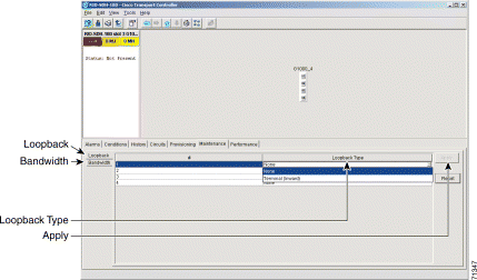
When a G1000-4 card is installed in the ONS 15454 SDH, the Maintenance tab under CTC card view reveals a Maintenance screen with two tabs Loopback and Bandwidth. The Loopback screen allows you to put an individual G1000-4 port into a Terminal (inward) loopback. The Bandwidth screen displays the amount of current STM bandwidth the card is using.
Table 9-12 G1000-4 Maintenance Screen Values
|
|
Caution Use Loopback only for the initial test and turn-up of the card and SDH network tests. Do not put the card in Loopback when the G1000-4 ports are in service and attached to a data network. Loopbacks can corrupt the forwarding tables used in data networking. |
|
Note For more information about using loopbacks with the ONS 15454 SDH, refer to the "Network Tests" section of the Cisco ONS 15454 SDH Troubleshooting and Maintenance Guide. |
CTC provides Ethernet performance information that includes line-level parameters, the amount of port bandwidth used, and historical Ethernet statistics.
The Ethernet statistics screen lists Ethernet parameters at the line level. Table 9-13 defines the parameters. Display the CTC card view for the Ethernet card and click the Performance > Statistics tabs to display the screen.
The Baseline button resets the statistics values on the Statistics screen to zero. The Refresh button manually refreshes statistics. Auto-Refresh sets a time interval for automatic refresh of statistics to occur.
The G1000-4 Statistics screen also has a Clear button. The Clear button sets the values on the card to zero. Using the Clear button will not cause the G1000-4 to reset.
Table 9-13 Ethernet Parameters
|
The Line Utilization window shows the percentage of line, or port, bandwidth used and the percentage used in the past. Display the CTC card view and click the Performance and Utilization tabs to display the screen. From the Interval menu, choose a time segment interval. Valid intervals are 1 minute, 15 minutes, 1 hour, and 1 day. Press Refresh to update the data.
Line utilization is calculated with the following formula:
((inOctets + outOctets) + (inPkts + outPkts) * 20)) * 8/100%interval * maxBaseRate * 2.
The interval is defined in seconds. maxBaseRate is defined by raw bits/second in one direction for the Ethernet port (i.e. 1 Gbps). maxBaseRate is multiplied by 2 in the denominator to determine the raw bit rate in both directions.
|
Note Line utilization numbers express the average of ingress and egress traffic as a percentage of capacity. |
The Ethernet History screen lists past Ethernet statistics. At the CTC card view, click the Performance tab and History subtab to view the screen. Choose the appropriate port from the Line menu and the appropriate interval from the Interval menu. Press Refresh to update the data. Table 9-13 defines the listed parameters.
Display an E-series Ethernet card in CTC card view and choose the Maintenance tab to display MAC address and bandwidth information.
A MAC address is a hardware address that physically identifies a network device. The ONS 15454 SDH MAC table, also known as the MAC forwarding table, will allow you to see all the MAC addresses attached to the enabled ports of an E series Ethernet card or an E series Ethernet Group. This includes the MAC address of the network device attached directly to the port and any MAC addresses on the network linked to the port. The MAC addresses table lists the MAC addresses stored by the ONS 15454 SDH and the VLAN, Slot/Port/STM, and circuit that links the ONS 15454 SDH to each MAC address (Figure 9-38).
Step 2 Select the appropriate Ethernet card or Ethergroup from the Layer 2 Domain pull-down menu.
Step 3 Click Retrieve for the ONS 15454 SDH to retrieve and display the current MAC IDs.
The Trunk Utilization screen is similar to the Line Utilization screen, but Trunk Utilization shows the percentage of circuit bandwidth used rather than the percentage of line bandwidth used. Click the Maintenance > Ether Bridge > Trunk Utilization tabs to view the screen. Choose a time segment interval from the Interval menu.
|
Note The percentage shown is the average of ingress and egress traffic. |
The ONS 15454 SDH features Remote Monitoring (RMON) that allows network operators to monitor the health of the network with a Network Management System (NMS). For a detailed description of the ONS SNMP implementation, see the "SNMP."
One of the ONS 15454 SDH's RMON MIBs is the Alarm group. The alarm group consists of the alarmTable. An NMS uses the alarmTable to find the alarm-causing thresholds for network performance. The thresholds apply to the current 15-minute interval and the current 24-hour interval. RMON monitors several variables, such as Ethernet collisions, and triggers an event when the variable crosses a threshold during that time interval. For example, if a threshold is set at 1000 collisions and 1001 collisions occur during the 15-minute interval, an event triggers. CTC allows you to provision these thresholds for Ethernet statistics.
|
Note You can find performance monitoring specifications for all other cards in the Cisco ONS 15454 SDH Troubleshooting and Maintenance Guide. |
|
Note The following tables define the variables you can provision in CTC. For example, to set the collision threshold, choose etherStatsCollisions from the Variable menu. |
Table 9-15 Ethernet Threshold Variables (MIBs)
|
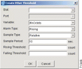
Step 2 Click the Provisioning > Etherbridge > Thresholds tabs.
Step 3 Click Create.
The Create Ether Threshold dialog box opens.
Step 4 From the Slot menu, choose the appropriate Ethernet card.
Step 5 From the Port menu, choose the Port on the Ethernet card.
Step 6 From the Variable menu, choose the variable. Table 9-15 lists and defines the Ethernet Threshold Variables available in this field.
Step 7 From Alarm Type, indicate whether the event will be triggered by the rising threshold, falling threshold, or both the rising and falling thresholds.
Step 8 From the Sample Type pull-down menu, choose either Relative or Absolute. Relative restricts the threshold to use the number of occurrences in the user-set sample period. Absolute sets the threshold to use the total number of occurrences, regardless of any time period.
Step 9 Type in an appropriate number of seconds for the Sample Period.
Step 10 Type in the appropriate number of occurrences for the Rising Threshold.
|
Note For a rising type of alarm to fire, the measured value must shoot from below the falling threshold to above the rising threshold. For example, if a network is running below a falling threshold of 400 collisions every 15 seconds and a problem causes 1001 collisions in 15 seconds, these occurrences fire an alarm. |
Step 11 Type in the appropriate number of occurrences for the Falling Threshold. In most cases a falling threshold is set lower than the rising threshold.
A falling threshold is the counterpart to a rising threshold. When the number of occurrences is above the rising threshold and then drops below a falling threshold, it resets the rising threshold. For example, when the network problem that caused 1001 collisions in 15 minutes subsides and creates only 799 collisions in 15 minutes, occurrences fall below a falling threshold of 800 collisions. This resets the rising threshold so that if network collisions again spike over a 1000 per 15 minute period, an event again triggers when the rising threshold is crossed. An event is triggered only the first time a rising threshold is exceeded (otherwise a single network problem might cause a rising threshold to be exceeded multiple times and cause a flood of events).
Step 12 Click the OK button to complete the procedure.
![]()
![]()
![]()
![]()
![]()
![]()
![]()
![]()
Posted: Thu Jul 24 12:14:12 PDT 2003
All contents are Copyright © 1992--2003 Cisco Systems, Inc. All rights reserved.
Important Notices and Privacy Statement.