|
|

Table Of Contents
Multiplexer and Demultiplexer Cards
5.2.1 Class 1 Laser Product Labels
5.2.2 Class 1M Laser Product Cards
5.3.3 32MUX-O Card-Level Indicators
5.3.4 32MUX-O Port-Level Indicators
5.4.2 32DMX-O Card-Level Indicators
5.4.3 32DMX-O Port-Level Indicators
5.5.3 4MD-xx.x Card-Level Indicators
5.5.4 4MD-xx.x Port-Level Indicators
Multiplexer and Demultiplexer Cards
This chapter describes legacy multiplexer and demultiplexer cards used in Cisco ONS 15454 dense wavelength division multiplexing (DWDM) networks. For installation and card turn-up procedures, refer to the Cisco ONS 15454 DWDM Procedure Guide. For card safety and compliance information, refer to the Cisco Optical Transport Products Safety and Compliance Information document.
Note
Unless otherwise specified, "ONS 15454" refers to both ANSI and ETSI shelf assemblies.
Chapter topics include:
Note
5.1 Card Overview
The card overview section contains card summary, compatibility, interface class, and channel allocation plan information for legacy multiplexer and demultiplexer cards.
Note
5.1.1 Card Summary
Table 5-1 lists and summarizes the functions of the 32MUX-O, 32DMX-O, and 4MD-xx.x cards.
Table 5-1 Multiplexer and Demultiplexer Cards
The 32MUX-O has five sets of ports located on the faceplate. It operates in Slots 1 to 5 and 12 to 16.
See the "32MUX-O Card" section.
The 32DMX-O has five sets of ports located on the faceplate. It operates in Slots 1 to 5 and 12 to 16.
The 4MD-xx.x card has five sets of ports located on the faceplate. It operates in Slots 1 to 6 and 12 to 17.
See the "4MD-xx.x Card" section.
5.1.2 Card Compatibility
Table 5-2 lists the CTC software compatibility for each card.
5.1.3 Interface Classes
The 32MUX-O, 32DMX-O, and 4MD-xx.x cards have different input and output optical channel signals depending on the interface card where the input signal originates. The input interface cards have been grouped in classes listed in Table 5-3. The subsequent tables list the optical performance and output power of each interface class.
Table 5-4 lists the optical performance parameters for 10-Gbps cards that provide signal input to multiplexer and demultiplexer cards.
Table 5-4 10-Gbps Interface Optical Performance
Maximum bit rate
10 Gbps
10 Gbps
10 Gbps
10 Gbps
Regeneration
3R
3R
3R
3R
FEC
Yes
No
No
Yes (E-FEC)
Threshold
Optimum
Average
Average
Optimum
Maximum BER2
10-15
10-12
10-12
10-15
OSNR 1 sensitivity
23 dB
9 dB
23 dB
19 dB
19 dB
20 dB
8 dB
Power sensitivity
-24 dBm
-18 dBm
-21 dBm
-20 dBm
-22 dBm
-26 dBm
-18 dBm
Power overload
-8 dBm
-8 dBm
-9 dBm
-8 dBm
Transmitted Power Range3
10-Gbps multirate transponder/10-Gbps FEC transponder (TXP_MR_10G)
+2.5 to 3.5 dBm
+2.5 to 3.5 dBm
—
—
OC-192 LR ITU
—
—
+3.0 to 6.0 dBm
—
10-Gbps multirate transponder/10-Gbps FEC transponder (TXP_MR_10E)
+3.0 to 6.0 dBm
+3.0 to 6.0 dBm
—
+3.0 to 6.0 dBm
Dispersion compensation tolerance
+/-800 ps/nm
+/-1,000 ps/nm
+/-1,000 ps/nm
+/-800 ps/nm
1 OSNR = optical signal-to-noise ratio
2 BER = bit error rate
3 These values, decreased by patchcord and connector losses, are also the input power values for the OADM cards.
Table 5-5 lists the optical interface performance parameters for 2.5-Gbps cards that provide signal input to multiplexer and demultiplexer cards.
Table 5-5 2.5-Gbps Interface Optical Performance
Maximum bit rate
2.5 Gbps
2.5 Gbps
2.5 Gbps
2.5 Gbps
1.25 Gbps
2.5 Gbps
Regeneration
3R
3R
2R
3R
3R
3R
FEC
Yes
No
No
No
No
No
Threshold
Average
Average
Average
Average
Average
Average
Maximum BER
10-15
10-12
10-12
10-12
10-12
10-12
OSNR sensitivity
14 dB
6 dB
14 dB
10 dB
15 dB
14 dB
11 dB
13 dB
8 dB
12 dB
Power sensitivity
-31 dBm
-25 dBm
-30 dBm
-23 dBm
-24 dBm
-27 dBm
-33 dBm
-28 dBm
-18 dBm
-26 dBm
Power overload
-9 dBm
-9 dBm
-9 dBm
-9 dBm
-7 dBm
-17dBm
Transmitted Power Range1
TXP_MR_2.5G
-1.0 to 1.0 dBm
-1.0 to 1.0 dBm
-1.0 to 1.0 dBm
-2.0 to 0 dBm
TXPP_MR_2.5G
-4.5 to -2.5 dBm
-4.5 to -2.5 dBm
-4.5 to -2.5 dBm
MXP_MR_2.5G
—
+2.0 to +4.0 dBm
—
MXPP_MR_2.5G
—
-1.5 to +0.5 dBm
—
2/4 port GbE Transponder (GBIC WDM 100GHz)
+2.5 to 3.5 dBm
—
Dispersion compensation tolerance
-1200 to +5400 ps/nm
-1200 to +5400 ps/nm
-1200 to +3300 ps/nm
-1200 to +3300 ps/nm
-1000 to +3600 ps/nm
-1000 to +3200 ps/nm
1 These values, decreased by patchcord and connector losses, are also the input power values for the OADM cards.
5.1.4 Channel Allocation Plan
ONS 15454 DWDM multiplexer and demultiplexer cards are designed for use with specific channels in the C band and L band. In most cases, the channels for these cards are either numbered (for example, 1 to 32 or 1 to 40) or delimited (odd or even). Client interfaces must comply with these channel assignments to be compatible with the ONS 15454 system.
Table 5-6 lists the channel IDs and wavelengths assigned to the C-band DWDM channels.
Note
Table 5-7 lists the channel IDs and wavelengths assigned to the L-band channels.
5.2 Safety Labels
This section explains the significance of the safety labels attached to some of the cards. The faceplates of the cards are clearly labeled with warnings about the laser radiation levels. You must understand all warning labels before working on these cards.
5.2.1 Class 1 Laser Product Labels
The 32MUX-O card has a Class 1 laser. The labels that appear on the card are described in the following sections.
5.2.1.1 Class 1 Laser Product Label
The Class 1 Laser Product label is shown in Figure 5-1.
Figure 5-1 Class 1 Laser Product Label
Class 1 lasers are products whose irradiance does not exceed the Maximum Permissible Exposure (MPE) value. Therefore, for Class 1 laser products the output power is below the level at which it is believed eye damage will occur. Exposure to the beam of a Class 1 laser will not result in eye injury and may therefore be considered safe. However, some Class 1 laser products may contain laser systems of a higher class but there are adequate engineering control measures to ensure that access to the beam is not reasonably likely. Anyone who dismantles a Class 1 laser product that contains a higher Class laser system is potentially at risk of exposure to a hazardous laser beam
5.2.1.2 Hazard Level 1 Label
The Hazard Level 1 label is shown in Figure 5-2.
Figure 5-2 Hazard Level Label
The Hazard Level label warns users against exposure to laser radiation of Class 1 limits calculated in accordance with IEC60825-1 Ed.1.2.
5.2.1.3 Laser Source Connector Label
The Laser Source Connector label is shown in Figure 5-3.
Figure 5-3 Laser Source Connector Label
This label indicates that a laser source is present at the optical connector where the label has been placed.
5.2.1.4 FDA Statement Label
The FDA Statement label is shown in Figure 5-4.
Figure 5-4 FDA Statement Label
This label shows compliance to FDA standards and that the hazard level classification is in accordance with IEC60825-1 Am.2 or Ed.1.2.
5.2.1.5 Shock Hazard Label
The Shock Hazard label is shown in Figure 5-5.
Figure 5-5 Shock Hazard Label
This label alerts personnel to electrical hazard within the card. The potential of shock hazard exists when removing adjacent cards during maintenance, and touching exposed electrical circuitry on the card itself.
5.2.2 Class 1M Laser Product Cards
The 32DMX-O and 4MD-xx.x cards have Class IM lasers. The labels that appear on these cards are described in the following subsections.
5.2.2.1 Class 1M Laser Product Label
The Class 1M Laser Product label is shown in Figure 5-6.
Figure 5-6 Class 1M Laser Product Label
Class 1M lasers are products that produce either a highly divergent beam or a large diameter beam. Therefore, only a small part of the whole laser beam can enter the eye. However, these laser products can be harmful to the eye if the beam is viewed using magnifying optical instruments.
5.2.2.2 Hazard Level 1M Label
The Hazard Level 1M label is shown in Figure 5-7.
Figure 5-7 Hazard Level Label
The Hazard Level label warns users against exposure to laser radiation of Class 1 limits calculated in accordance with IEC60825-1 Ed.1.2.
5.2.2.3 Laser Source Connector Label
The Laser Source Connector label is shown in Figure 5-8.
Figure 5-8 Laser Source Connector Label
This label indicates that a laser source is present at the optical connector where the label has been placed.
5.2.2.4 FDA Statement Label
The FDA Statement label is shown in Figure 5-9.
Figure 5-9 FDA Statement Label
This label shows compliance to FDA standards and that the hazard level classification is in accordance with IEC60825-1 Am.2 or Ed.1.2.
5.2.2.5 Shock Hazard Label
The Shock Hazard label is shown in Figure 5-5.
Figure 5-10 Shock Hazard Label
This label alerts personnel to electrical hazard within the card. The potential of shock hazard exists when removing adjacent cards during maintenance, and touching exposed electrical circuitry on the card itself.
5.3 32MUX-O Card
Note
The 32-Channel Multiplexer (32MUX-O) card multiplexes 32 100-GHz-spaced channels identified in the channel plan. The 32MUX-O card takes up two slots in an ONS 15454 and can be installed in Slots 1 to 5 and 12 to 16.
The 32MUX-O features include:
•
•
•
An additional optical monitoring port with 1:99 splitting ratio is available.
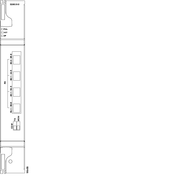
Figure 5-11 shows the 32MUX-O faceplate.
Figure 5-11 32MUX-O Faceplate
For information on safety labels for the card, see the "Class 1 Laser Product Labels" section.
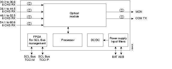
Figure 5-12 shows a block diagram of the 32MUX-O card.
Figure 5-12 32MUX-O Block Diagram
The 32MUX-O card has four receive connectors that accept multifiber push-on (MPO) cables on its front panel for the client input interfaces. MPO cables break out into eight separate cables. The 32MUX-O card also has two LC-PC-II optical connectors, one for the main output and the other for the monitor port.
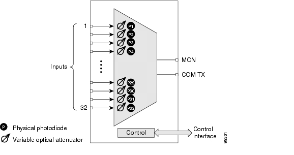
Figure 5-13 shows the 32MUX-O optical module functional block diagram.
Figure 5-13 32MUX-O Optical Module Functional Block Diagram
5.3.1 Channel Plan
The 32MUX-O is typically used in hub nodes and provides the multiplexing of 32 channels, spaced at 100 GHz, into one fiber before their amplification and transmission along the line. The channel plan is shown in Table 5-8.
Table 5-8 32MUX-O Channel Plan
1
30.3
195.9
1530.33
2
31.2
195.8
1531.12
3
31.9
195.7
1531.90
4
32.6
195.6
1532.68
5
34.2
195.4
1534.25
6
35.0
195.3
1535.04
7
35.8
195.2
1535.82
8
36.6
195.1
1536.61
9
38.1
194.9
1538.19
10
38.9
194.8
1538.98
11
39.7
194.7
1539.77
12
40.5
194.6
1540.56
13
42.1
194.4
1542.14
14
42.9
194.3
1542.94
15
43.7
194.2
1543.73
16
44.5
194.1
1544.53
17
46.1
193.9
1546.12
18
46.9
193.8
1546.92
19
47.7
193.7
1547.72
20
48.5
193.6
1548.51
21
50.1
193.4
1550.12
22
50.9
193.3
1550.92
23
51.7
193.2
1551.72
24
52.5
193.1
1552.52
25
54.1
192.9
1554.13
26
54.9
192.8
1554.94
27
55.7
192.7
1555.75
28
56.5
192.6
1556.55
29
58.1
192.4
1558.17
30
58.9
192.3
1558.98
31
59.7
192.2
1559.79
32
60.6
192.1
1560.61
1 The Channel Number column is only for reference purposes. The channel ID is consistent with the ONS 15454 and is used in card identification.
5.3.2 Power Monitoring
Physical photodiodes P1 through P32 monitor the power for the 32MUX-O card. The returned power level values are calibrated to the ports as shown in Table 5-9.
5.3.3 32MUX-O Card-Level Indicators
The 32MUX-O card has three card-level LED indicators, described in Table 5-10.
5.3.4 32MUX-O Port-Level Indicators
You can find the status of the card ports using the LCD screen on the ONS 15454 fan-tray assembly. Use the LCD to view the status of any port or card slot; the screen displays the number and severity of alarms for a given port or slot. The 32MUX-O card has five sets of ports located on the faceplate.
COM TX is the line output. COM MON is the optical monitoring port. The xx.x to yy.y RX ports represent the four groups of eight channels ranging from wavelength xx.x to wavelength yy.y, according to the channel plan.
5.4 32DMX-O Card
Note
The 32-Channel Demultiplexer (32DMX-O) card demultiplexes 32 100-GHz-spaced channels identified in the channel plan. The 32DMX-O takes up two slots in an ONS 15454 and can be installed in Slots 1 to 5 and 12 to 16.
The 32DMX-O features include:
•
•
•
Note
•
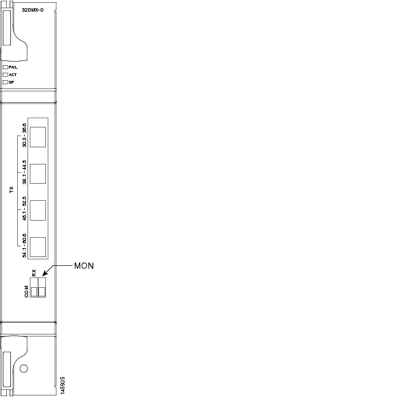
Figure 5-14 shows the 32DMX-O card faceplate.
Figure 5-14 32DMX-O Faceplate
For information on safety labels for the card, see the "Class 1M Laser Product Cards" section.
Figure 5-15 shows a block diagram of the 32DMX-O card.
Figure 5-15 32DMX-O Block Diagram
Figure 5-16 shows the 32DMX-O optical module functional block diagram.
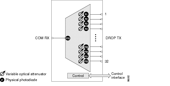
Figure 5-16 32DMX-O Optical Module Functional Block Diagram
5.4.1 Power Monitoring
Physical photodiodes P1 through P33 monitor the power for the 32DMX-O card. The returned power level values are calibrated to the ports as shown in Table 5-11.
Table 5-11 32DMX-O Port Calibration
P1-P32
DROP
DROP TX
P33
INPUT COM
COM RX
5.4.2 32DMX-O Card-Level Indicators
The 32DMX-O card has three card-level LED indicators, described in Table 5-12.
5.4.3 32DMX-O Port-Level Indicators
You can find the status of the card ports using the LCD screen on the ONS 15454 fan-tray assembly. Use the LCD to view the status of any port or card slot; the screen displays the number and severity of alarms for a given port or slot. The 32DMX-O card has five sets of ports located on the faceplate. MON is the output monitor port. COM RX is the line input. The xx.x to yy.y TX ports represent the four groups of eight channels ranging from wavelength xx.x to wavelength yy.y according to the channel plan.
5.5 4MD-xx.x Card
Note
The 4-Channel Multiplexer/Demultiplexer (4MD-xx.x) card multiplexes and demultiplexes four 100-GHz-spaced channels identified in the channel plan. The 4MD-xx.x card is designed to be used with band OADMs (both AD-1B-xx.x and AD-4B-xx.x).
The card is bidirectional. The demultiplexer and multiplexer functions are implemented in two different sections of the same card. In this way, the same card can manage signals flowing in opposite directions.
There are eight versions of this card that correspond with the eight sub-bands specified in Table 5-13. The 4MD-xx.x can be installed in Slots 1 to 6 and 12 to 17.
The 4MD-xx.x has the following features implemented inside a plug-in optical module:
•
•
•
•
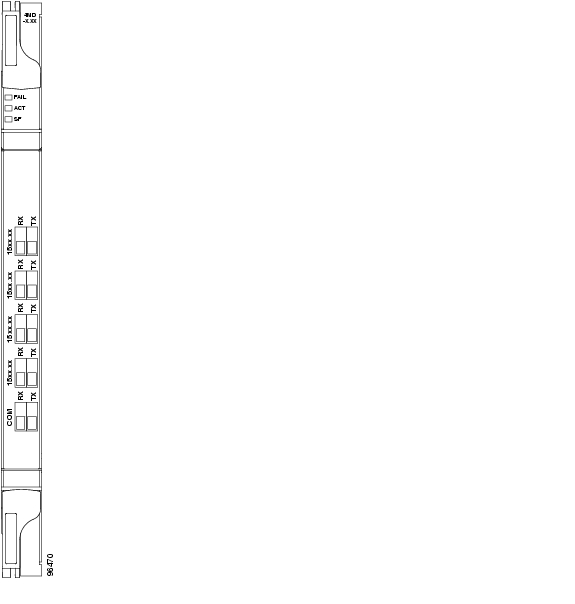
Figure 5-17 shows the 4MD-xx.x faceplate.
Figure 5-17 4MD-xx.x Faceplate
For information on safety labels for the card, see the "Class 1M Laser Product Cards" section.
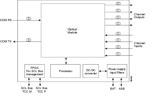
Figure 5-18 shows a block diagram of the 4MD-xx.x card.
Figure 5-18 4MD-xx.x Block Diagram
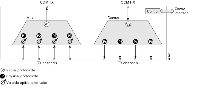
Figure 5-19 shows the 4MD-xx.x optical module functional block diagram.
Figure 5-19 4MD-xx.x Optical Module Functional Block Diagram
The optical module shown in Figure 5-19 is optically passive and consists of a cascade of interferential filters that perform the channel multiplexing and demultiplexing functions.
VOAs are present in every input path of the multiplex section in order to regulate the optical power of each multiplexed channel. Some optical input and output ports are monitored by means of photodiodes implemented both for power control and for safety purposes. An internal control manages VOA settings and functionality as well as photodiode detection and alarm thresholds. The power at the main output and input ports is monitored through the use of virtual photodiodes. A virtual photodiode is implemented in the firmware of the plug-in module. This firmware calculates the power on a port, summing the measured values from all single channel ports (and applying the proper path insertion loss) and then providing the TCC2/TCC2P card with the obtained value.
5.5.1 Wavelength Pairs
Table 5-13 shows the band IDs and the add/drop channel IDs for the 4MD-xx.x card.
5.5.2 Power Monitoring
Physical photodiodes P1 through P8 and virtual photodiodes V1 and V2 monitor the power for the 4MD-xx.x card. The returned power level values are calibrated to the ports as shown in Table 5-14.
Table 5-14 4MD-xx.x Port Calibration
P1-P4
ADD
COM TX
P5-P8
DROP
DROP TX
V1
OUT COM
COM TX
V2
IN COM
COM RX
5.5.3 4MD-xx.x Card-Level Indicators
The 4MD-xx.x card has three card-level LED indicators, described in Table 5-15.
5.5.4 4MD-xx.x Port-Level Indicators
You can find the status of the card ports using the LCD screen on the ONS 15454 fan-tray assembly. Use the LCD to view the status of any port or card slot; the screen displays the number and severity of alarms for a given port or slot. The 4MD-xx.x card has five sets of ports located on the faceplate. COM RX is the line input. COM TX is the line output. The 15xx.x TX ports represent demultiplexed channel outputs 1 to 4. The 15xx.x RX ports represent multiplexed channel inputs 1 to 4.
![]()
![]()
![]()
![]()
![]()
![]()
![]()
![]()
Posted: Mon Oct 22 05:55:17 PDT 2007
All contents are Copyright © 1992--2007 Cisco Systems, Inc. All rights reserved.
Important Notices and Privacy Statement.