|
|

Table Of Contents
4.2 Class 1M Laser Safety Labels
4.2.1 Class 1M Laser Product Label
4.2.3 Laser Source Connector Label
4.3.3 OPT-PRE Power Monitoring
4.3.4 OPT-PRE Amplifier Card-Level Indicators
4.3.5 OPT-PRE Port-Level Indicators
4.4.3 OPT-BST Power Monitoring
4.4.4 OPT-BST Card-Level Indicators
4.4.5 OPT-BST Port-Level Indicators
4.5.1 OPT-BST-E Faceplate Ports
4.5.2 OPT-BST-E Block Diagrams
4.5.3 OPT-BST-E Power Monitoring
4.5.4 OPT-BST-E Card-Level Indicators
4.5.5 OPT-BST-E Port-Level Indicators
4.6.1 OPT-BST-L Faceplate Ports
4.6.2 OPT-BST-L Block Diagrams
4.6.3 OPT-BST-L Power Monitoring
4.6.4 OPT-BST-L Card-Level Indicators
4.6.5 OPT-BST-L Port-Level Indicators
4.7.1 OPT-AMP-L Faceplate Ports
4.7.2 OPT-AMP-L Block Diagrams
4.7.3 OPT-AMP-L Power Monitoring
4.7.4 OPT-AMP-L Card-Level Indicators
4.7.5 OPT-AMP-L Port-Level Indicators
4.8.1 OPT-AMP-17-C Faceplate Ports
4.8.2 OPT-AMP-17-C Block Diagrams
4.8.3 OPT-AMP-17-C Automatic Power Control
4.8.4 OPT-AMP-17-C Power Monitoring
4.8.5 OPT-AMP-17-C Card-Level Indicators
4.8.6 OPT-AMP-17-C Port-Level Indicators
Optical Amplifier Cards
This chapter describes the optical amplifier cards used in Cisco ONS 15454 dense wavelength division multiplexing (DWDM) networks. For installation and card turn-up procedures, refer to the Cisco ONS 15454 DWDM Procedure Guide. For card safety and compliance information, refer to the Cisco Optical Transport Products Safety and Compliance Information document.
Note
Unless otherwise specified, "ONS 15454" refers to both ANSI and ETSI shelf assemblies.
Chapter topics include:
•
4.1 Card Overview
This section provides summary and compatibility information for the optical amplifier cards.
Note
Optical amplifiers are used in amplified nodes (such as hub nodes), amplified OADM nodes, and line amplifier nodes. The six types of ONS 15454 DWDM amplifiers are:
•
•
•
•
•
•
Note
Optical amplifier card architecture includes an optical plug-in module with a controller that manages optical power, laser current, and temperature control loops. An amplifier also manages communication with the TCC2/TCC2P card and operation, administration, maintenance, and provisioning (OAM&P) functions such as provisioning, controls, and alarms.
Optical amplifiers have a linear power feature that enables them to remain in constant gain mode if the gain falls below 28 dB. However, for longer spans, you might have to manually place amplifiers in constant power mode.
If span loss degradation causes channel loss or reprovisioning while an amplifier is in constant power mode, the amplifier cannot dynamically adjust its output power to compensate for a decreased (or later increased) number of channels. In this way, constant power mode affects automatic power control (APC) requirements.
4.1.1 Card Summary
Table 4-1 lists and summarizes the functions of each optical amplifier card.
Table 4-1 Optical Amplifier Cards for the ONS 15454
The OPT-PRE amplifier has five optical ports (three sets) located on the faceplate. It operates in Slots 1 to 6 and 12 to 17.
See the "OPT-PRE Amplifier Card" section.
The OPT-BST amplifier has four sets of optical ports located on the faceplate. It operates in Slots 1 to 6 and 12 to 17.
See the "OPT-BST Amplifier Card" section.
The OPT-BST-E amplifier has four sets of optical ports located on the faceplate. It operates in Slots 1 to 6 and 12 to 17.
See the "OPT-BST-E Amplifier Card" section.
The OPT-BST-L L-band amplifier has four sets of optical ports located on the faceplate. It operates in Slots 1 to 6 and 12 to 17.
See the "OPT-BST-L Amplifier Card" section.
The OPT-AMP-L L-band preamplifier have five sets of optical ports located on the faceplate. It is a two-slot card that operates in Slots 1 to 6 and 12 to 17.
See the "OPT-AMP-L Card" section.
The OPT-AMP-17-C C-band low-gain preamplifier/booster amplifier has four sets of optical ports located on the faceplate. It operates in Slots 1 to 6 and 12 to 17.
See the "OPT-AMP-17-C Card" section.
4.1.2 Card Compatibility
Table 4-2 lists the Cisco Transport Controller (CTC) software compatibility for each optical amplifier card.
4.2 Class 1M Laser Safety Labels
This section explains the significance of the safety labels attached to the optical amplifier cards. The faceplates of the cards are clearly labeled with warnings about the laser radiation levels. You must understand all warning labels before working on these cards.
4.2.1 Class 1M Laser Product Label
Figure 4-1 shows the Class 1M Laser Product label. Class 1M lasers are products that produce either a highly divergent beam or a large diameter beam. Therefore, only a small part of the whole laser beam can enter the eye. However, these laser products can be harmful to the eye if the beam is viewed using magnifying optical instruments.
Figure 4-1 Class 1M Laser Product Label
4.2.2 Hazard Level 1M Label
Figure 4-2 shows the Hazard Level 1M label. The Hazard Level label warns users against exposure to laser radiation calculated in accordance with IEC60825-1 Ed.1.2.
Figure 4-2 Hazard Level Label
4.2.3 Laser Source Connector Label
Figure 4-3 shows the Laser Source Connector label. This label indicates that a laser source is present at the optical connector where the label appears.
Figure 4-3 Laser Source Connector Label
4.2.4 FDA Statement Label
Figure 4-4 shows the FDA Statement label. This label represents compliance to FDA standards and a hazard-level classification in accordance with IEC60825-1 Am.2 or Ed.1.2.
Figure 4-4 FDA Statement Label
4.2.5 Shock Hazard Label
Figure 4-5 shows the Shock Hazard label. This label alerts you to an electrical hazard within the card. The potential for shock exists when you remove adjacent cards during maintenance or touch exposed electrical circuity on the card.
Figure 4-5 Shock Hazard Label
4.3 OPT-PRE Amplifier Card
Note
Note
The OPT-PRE is a C-band, DWDM, two-stage erbium-doped fiber amplifier (EDFA) with midamplifier loss (MAL) that can be connected to a dispersion compensating unit (DCU). The OPT-PRE is equipped with a built-in variable optical attenuator (VOA) that controls the gain tilt and can also be used to pad the DCU to a reference value. You can install the OPT-PRE in Slots 1 to 6 and 12 to 17. The card is designed to support up to 80 channels at 50-GHz channel spacing. The OPT-PRE features include:
•
•
•
•
•
•
•
•
•
•
•
Note
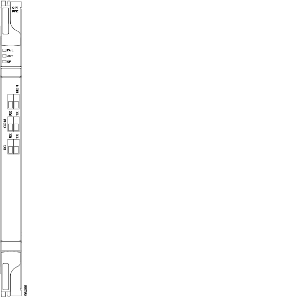
4.3.1 OPT-PRE Faceplate Ports
The OPT-PRE amplifier has five optical ports located on the faceplate:
•
•
•
•
•
Figure 4-6 shows the OPT-PRE amplifier card faceplate.
Figure 4-6 OPT-PRE Faceplate
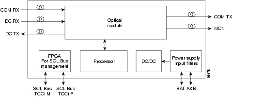
4.3.2 OPT-PRE Block Diagrams
Figure 4-7 shows a simplified block diagram of the OPT-PRE card's features.
Figure 4-7 OPT-PRE Block Diagram
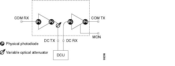
Figure 4-8 shows the a block diagram of how the OPT-PRE optical module functions.
Figure 4-8 OPT-PRE Optical Module Functional Block Diagram
4.3.3 OPT-PRE Power Monitoring
Physical photodiodes P1, P2, P3, and P4 monitor the power for the OPT-PRE card. Table 4-3 shows the returned power level values calibrated to each port.
Table 4-3 OPT-PRE Port Calibration
P1
Input Com
COM RX
P2
Output DC
DC TX
P3
Input DC
DC RX
P4
Output COM (Total Output)
COM TX
Output COM (Signal Output)
4.3.4 OPT-PRE Amplifier Card-Level Indicators
Table 4-4 shows the three card-level LED indicators on the OPT-PRE amplifier card.
4.3.5 OPT-PRE Port-Level Indicators
You can determine the status of the card ports using the LCD screen on the ONS 15454 fan-tray assembly. Use the LCD to view the status of any port or card slot; the screen displays the number and severity of alarms for a given port or slot.
4.4 OPT-BST Amplifier Card
Note
Note
The OPT-BST is designed to ultimately support up to 80 channels at 50-GHz channel spacing. The OPT-BST is a C-band, DWDM EDFA with optical service channel (OSC) add-and-drop capability. When an OPT-BST installed in the an ONS 15454, an OSCM card is also needed to process the OSC. You can install the OPT-BST in Slots 1 to 6 and 12 to 17. The card's features include:
•
•
•
•
•
•
•
•
•
•
•
•
Note
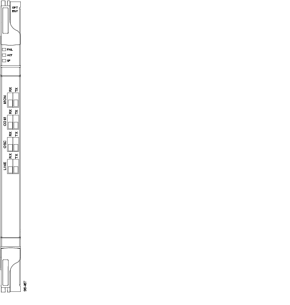
4.4.1 OPT-BST Faceplate Ports
The OPT-BST amplifier has eight optical ports located on the faceplate:
•
•
•
•
•
•
•
•
Figure 4-9 shows the OPT-BST amplifier card faceplate.
Figure 4-9 OPT-BST Faceplate
4.4.2 OPT-BST Block Diagrams
Figure 4-10 shows a simplified block diagram of the OPT-BST card's features.
Figure 4-10 OPT-BST Block Diagram
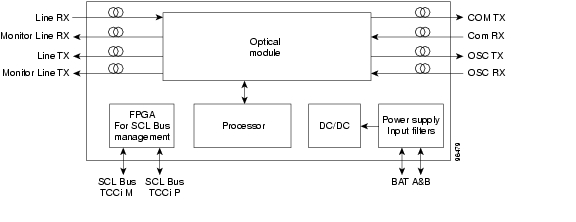
Figure 4-11 shows a block diagram of how the OPT-BST optical module functions.
Figure 4-11 OPT-BST Optical Module Functional Block Diagram
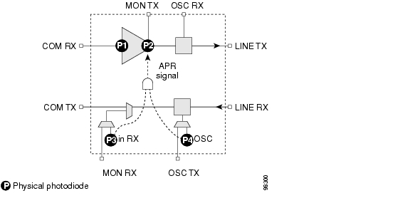
4.4.3 OPT-BST Power Monitoring
Physical photodiodes P1, P2, P3, and P4 monitor the power for the OPT-BST card. Table 4-5 shows the returned power level values calibrated to each port.
4.4.4 OPT-BST Card-Level Indicators
Table 4-6 describes the three card-level LED indicators on the OPT-BST card.
4.4.5 OPT-BST Port-Level Indicators
You can determine the status of the card ports using the LCD screen on the ONS 15454 fan-tray assembly. Use the LCD to view the status of any port or card slot; the screen displays the number and severity of alarms for a given port or slot.
4.5 OPT-BST-E Amplifier Card
Note
Note
The OPT-BST-E amplifier card is a gain-enhanced version of the OPT-BST card. It is designed to support up to 80 channels at 50-GHz channel spacing. The OPT-BST-E is a C-band, DWDM EDFA with OSC add-and-drop capability. When an OPT-BST-E installed, an OSCM card is needed to process the OSC. You can install the OPT-BST-E in Slots 1 to 6 and 12 to 17. The card's features include:
•
•
•
•
•
•
•
•
•
•
•
•
•
Note
4.5.1 OPT-BST-E Faceplate Ports
The OPT-BST-E amplifier card has eight optical ports located on the faceplate:
•
•
•
•
•
•
•
•
Figure 4-12 shows the OPT-BST-E amplifier card faceplate.
Figure 4-12 OPT-BST-E Faceplate
4.5.2 OPT-BST-E Block Diagrams
Figure 4-13 shows a simplified block diagram of the OPT-BST-E card's features.
Figure 4-13 OPT-BST-E Block Diagram
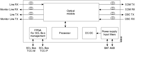
Figure 4-14 shows a block diagram of how the OPT-BST-E optical module functions.
Figure 4-14 OPT-BST-E Optical Module Functional Block Diagram
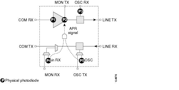
4.5.3 OPT-BST-E Power Monitoring
Physical photodiodes P1, P2, P3, and P4 monitor the power for the OPT-BST-E card. Table 4-7 shows the returned power level values calibrated to each port.
4.5.4 OPT-BST-E Card-Level Indicators
Table 4-8 describes the three card-level LED indicators on the OPT-BST-E amplifier card.
4.5.5 OPT-BST-E Port-Level Indicators
You can determine the status of the card ports using the LCD screen on the ONS 15454 fan-tray assembly. Use the LCD to view the status of any port or card slot; the screen displays the number and severity of alarms for a given port or slot.
4.6 OPT-BST-L Amplifier Card
Note
Note
The OPT-BST-L is an L-band, DWDM EDFA with OSC add-and-drop capability. The card is well suited for use in networks that employ dispersion shifted (DS) fiber or SMF-28 single-mode fiber. The OPT-BST-L is designed to ultimately support 64 channels at 50-GHz channel spacing, but in Software R8.0 is limited to 32 channels at 100-GHz spacing.When an ONS 15454 has an OPT-BST-L installed, an OSCM card is needed to process the OSC. You can install the OPT-BST-L in Slots 1 to 6 and 12 to 17. The card's features include:
•
•
•
•
•
•
•
•
•
•
•
•
•
Note
4.6.1 OPT-BST-L Faceplate Ports
The OPT-BST-L amplifier has eight optical ports located on the faceplate:
•
•
•
•
•
•
•
•
Figure 4-15 shows the OPT-BST-L card faceplate.
Figure 4-15 OPT-BST-L Faceplate
4.6.2 OPT-BST-L Block Diagrams
Figure 4-16 shows a simplified block diagram of the OPT-BST-L card's features.
Figure 4-16 OPT-BST-L Block Diagram
Figure 4-17 shows a block diagram of how the OPT-BST-L optical module functions.
Figure 4-17 OPT-BST-L Optical Module Functional Block Diagram
4.6.3 OPT-BST-L Power Monitoring
Physical photodiodes P1, P2, P3, P4, and P5 monitor the power for the OPT-BST-L card. Table 4-9 shows the returned power level values calibrated to each port.
4.6.4 OPT-BST-L Card-Level Indicators
Table 4-10 shows the three card-level LEDs on the OPT-BST-L card.
4.6.5 OPT-BST-L Port-Level Indicators
You can determine the status of the card ports using the LCD screen on the ONS 15454 fan-tray assembly. Use the LCD to view the status of any port or card slot; the screen displays the number and severity of alarms for a given port or slot.
4.7 OPT-AMP-L Card
Note
Note
The OPT-AMP-L is an L-band, DWDM optical amplifier card consisting of a two-stage EDFA with midstage access loss (MSL) for an external DCU and OSC add-and-drop capability. Using CTC, the card is provisionable as a preamplifier (OPT-PRE) or booster amplifier (OPT-BST), and is well suited for use in networks that employ DS or SMF-28 fiber. The amplifier can operate up to 64 optical transmission channels at 50-GHz channel spacing in the 1570 nm to 1605 nm wavelength range.
When an OPT-AMP-L installed, an OSCM card is needed to process the OSC. You can install the two-slot OPT-AMP-L in Slots 1 to 6 and 12 to 17.
The card has the following features:
•
•
•
•
•
•
•
•
•
•
•
•
•
Note
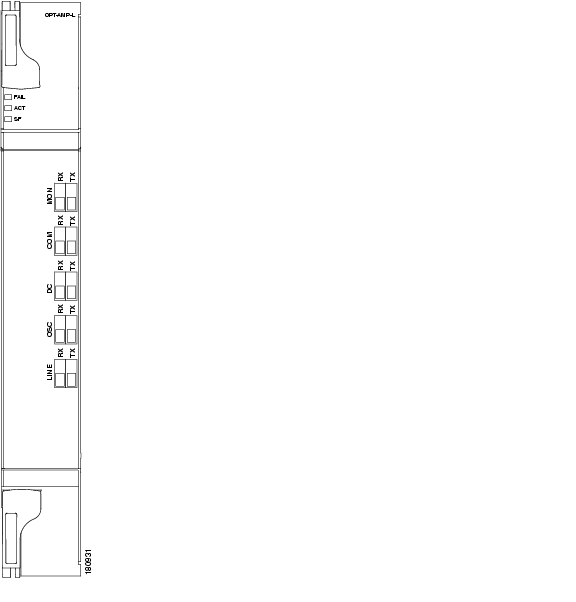
4.7.1 OPT-AMP-L Faceplate Ports
The OPT-AMP-L amplifier card has ten optical ports located on the faceplate:
•
•
•
•
•
•
•
•
•
•
Figure 4-18 shows the OPT-AMP-L card faceplate.
Figure 4-18 OPT-AMP-L Faceplate
4.7.2 OPT-AMP-L Block Diagrams
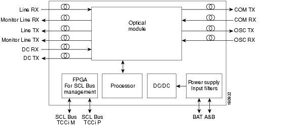
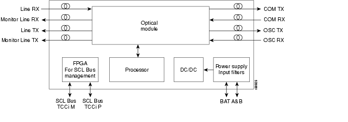
Figure 4-19 shows a simplified block diagram of the OPT-AMP-L card's features.
Figure 4-19 OPT-AMP-L Block Diagram
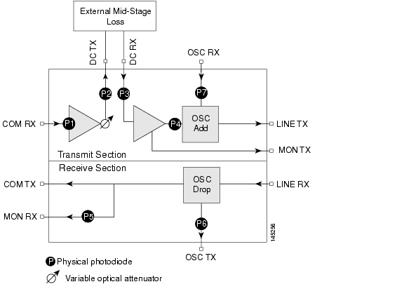
Figure 4-20 shows a block diagram of how the OPT-AMP-L optical module functions.
Figure 4-20 OPT-AMP-L Optical Module Functional Block Diagram
4.7.3 OPT-AMP-L Power Monitoring
Physical photodiodes P1 through P7 monitor the power for the OPT-AMP-L card. Table 4-11 shows the returned power level values calibrated to each port.
4.7.4 OPT-AMP-L Card-Level Indicators
Table 4-12 shows the three card-level LEDs on the OPT-AMP-L card.
4.7.5 OPT-AMP-L Port-Level Indicators
You can determine the status of the card ports using the LCD screen on the ONS 15454 fan-tray assembly. Use the LCD to view the status of any port or card slot; the screen displays the number and severity of alarms for a given port or slot.
4.8 OPT-AMP-17-C Card
Note
Note
The OPT-AMP-17-C is a 17-dB gain, C-band, DWDM EDFA amplifier/preamplifier with OSC add-and-drop capability. It supports 80 channels at 50-GHz channel spacing in the C-band (that is, the 1529 nm to 1562.5 nm wavelength range). When an ONS 15454 has an OPT-AMP-17-C installed, an OSCM card is needed to process the OSC. You can install the OPT-AMP-17-C in Slots 1 to 6 and 12 to 17.
The card's features include:
•
•
•
•
•
•
•
•
•
•
•
•
•
4.8.1 OPT-AMP-17-C Faceplate Ports
The OPT-AMP-17-C amplifier card has eight optical ports located on the faceplate:
•
•
•
•
•
•
•
•
Figure 4-21 shows the OPT-AMP-17-C amplifier card faceplate.
Figure 4-21 OPT-AMP-17-C Faceplate
4.8.2 OPT-AMP-17-C Block Diagrams
Figure 4-22 shows a simplified block diagram of the OPT-AMP-17C card's features.
Figure 4-22 OPT-AMP17-C Block Diagram
Figure 4-23 Figure 4-24 shows how the OPT-AMP-17-C optical module functions.
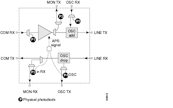
Figure 4-24 OPT-AMP-17-C Optical Module Functional Block Diagram
4.8.3 OPT-AMP-17-C Automatic Power Control
A transient gain range of 20 to 23 dB is available to APC in order to permit other amplifiers to reach their expected set points. However, operation in this range is not continuous. At startup, the OPT-AMP-17-C card caps the gain at a maximum of 20 dB.
Note
4.8.4 OPT-AMP-17-C Power Monitoring
Physical photodiodes P1, P2, P3, P4, and P5 monitor power for the OPT-AMP-17-C card. Table 4-13 shows the returned power level values calibrated to each port.
4.8.5 OPT-AMP-17-C Card-Level Indicators
Table 4-14 shows the three card-level LEDs on the OPT-AMP-17-C card.
4.8.6 OPT-AMP-17-C Port-Level Indicators
You can determine the status of the card ports using the LCD screen on the ONS 15454 fan-tray assembly. Use the LCD to view the status of any port or card slot; the screen displays the number and severity of alarms for a given port or slot.
![]()
![]()
![]()
![]()
![]()
![]()
![]()
![]()
Posted: Mon Oct 22 06:00:19 PDT 2007
All contents are Copyright © 1992--2007 Cisco Systems, Inc. All rights reserved.
Important Notices and Privacy Statement.