|
|

Table Of Contents
6.1.4 DWDM Card Channel Allocation Plan
6.2 Class 1M Laser Product Safety Lasers
6.2.1 Class 1M Laser Product Label
6.2.3 Laser Source Connector Label
6.3.2 AD-1C-xx.x Card-Level Indicators
6.3.3 AD-1C-xx.x Port-Level Indicators
6.4.3 AD-2C-xx.x Card-Level Indicators
6.4.4 AD-2C-xx.x Port-Level Indicators
6.5.3 AD-4C-xx.x Card-Level Indicators
6.5.4 AD-4C-xx.x Port-Level Indicators
6.6.2 AD-1B-xx.x Card-Level Indicators
6.6.3 AD-1B-xx.x Port-Level Indicators
6.7.2 AD-4B-xx.x Card-Level Indicators
6.7.3 AD-4B-xx.x Port-Level Indicators
Optical Add/Drop Cards
This chapter describes optical add/drop cards used in Cisco ONS 15454 dense wavelength division multiplexing (DWDM) networks. For installation and card turn-up procedures, refer to the Cisco ONS 15454 DWDM Procedure Guide. For card safety and compliance information, refer to the Cisco Optical Transport Products Safety and Compliance Information document.
Note
Unless otherwise specified, "ONS 15454" refers to both ANSI and ETSI shelf assemblies.
Chapter topics include:
•
6.1 Card Overview
The card overview section contains card overview, software compatibility, interface class, and channel allocation information for optical add/drop cards.
Note
Optical Add/Drop cards are divided into two groups: band optical add/drop multiplexer (OADM) and channel OADM cards. Band OADM cards add and drop one or four bands of adjacent channels. The cards in this chapter, including the 4-Band OADM (AD-4B-xx.x) and the 1-Band OADM (AD-1B-xx.x) are utilized only in the C band. Channel OADM cards add and drop one, two, or four adjacent channels; they include the 4-Channel OADM (AD-4C-xx.x), the 2-Channel OADM (AD-2C-xx.x), and the 1-Channel OADM (AD-1C-xx.x).
Note
6.1.1 Card Summary
Table 6-1 lists and summarizes the functions of the optical add/drop cards.
Table 6-1 Optical Add/Drop Cards
The AD-1C-xx.x card has three sets of ports located on the faceplate. It operates in Slots 1 to 6 and 12 to 17.
See the "AD-1C-xx.x Card" section.
The AD-2C-xx.x card has four sets of ports located on the faceplate. It operates in Slots 1 to 6 and 12 to 17.
See the "AD-2C-xx.x Card" section.
The AD-4C-xx.x card has six sets of ports located on the faceplate. It operates in Slots 1 to 6 and 12 to 17.
See the "AD-4C-xx.x Card" section.
The AD-1B-xx.x card has three sets of ports located on the faceplate. It operates in Slots 1 to 6 and 12 to 17.
See the "AD-1B-xx.x Card" section.
The AD-4B-xx.x card has six sets of ports located on the faceplate. It operates in Slots 1 to 6 and 12 to 17.
See the "AD-4B-xx.x Card" section.
6.1.2 Card Compatibility
Table 6-2 lists the CTC software compatibility for each optical add/drop card.
6.1.3 Interface Classes
The AD-1C-xx.x, AD-2C-xx.x, AD-4C-xx.x, AD-1B-xx.x, and AD-4B-xx.x cards have different input and output optical channel signals depending on the interface card where the input signal originates. The input interface cards have been grouped in classes listed in Table 6-3. The subsequent tables list the optical performances and output power of each interface class.
10-Gbps cards that provide signal input to the optical add/drop cards have the optical performance parameters listed in Table 6-4.
Table 6-4 10-Gbps Interface Optical Performance
(if appl.)
(if appl.)
(if appl.)Maximum bit rate
10 Gbps
10 Gbps
10 Gbps
10 Gbps
Regeneration
3R
3R
3R
3R
FEC
Yes
No
No
Yes (E-FEC)
Threshold
Optimum
Average
Average
Optimum
Maximum BER2
10-15
10-12
10-12
10-15
OSNR 1 sensitivity
23 dB
9 dB
23 dB
19 dB
19 dB
20 dB
8 dB
Power sensitivity
-24 dBm
-18 dBm
-21 dBm
-20 dBm
-22 dBm
-26 dBm
-18 dBm
Power overload
-8 dBm
-8 dBm
-9 dBm
-8 dBm
Transmitted Power Range3
10-Gbps multirate transponder/10-Gbps FEC transponder (TXP_MR_10G)
+2.5 to 3.5 dBm
+2.5 to 3.5 dBm
—
—
OC-192 LR ITU
—
—
+3.0 to 6.0 dBm
—
10-Gbps multirate transponder/10-Gbps FEC transponder (TXP_MR_10E)
+3.0 to 6.0 dBm
+3.0 to 6.0 dBm
—
+3.0 to 6.0 dBm
Dispersion compensation tolerance
+/-800 ps/nm
+/-1,000 ps/nm
+/-1,000 ps/nm
+/-800 ps/nm
1 OSNR = optical signal-to-noise ratio
2 BER = bit error rate
3 These values, decreased by patchcord and connector losses, are also the input power values for the OADM cards.
2.5-Gbps cards that provide signal input to the optical add/drop cards have the interface performance parameters listed in Table 6-5.
Table 6-5 2.5-Gbps Interface Optical Performance
(if appl.)
(if appl.)
(if appl.)
(if appl.)Maximum bit rate
2.5 Gbps
2.5 Gbps
2.5 Gbps
2.5 Gbps
1.25 Gbps
2.5 Gbps
Regeneration
3R
3R
2R
3R
3R
3R
FEC
Yes
No
No
No
No
No
Threshold
Average
Average
Average
Average
Average
Average
Maximum BER
10-15
10-12
10-12
10-12
10-12
10-12
OSNR sensitivity
14 dB
6 dB
14 dB
10 dB
15 dB
14 dB
11 dB
13 dB
8 dB
12 dB
Power sensitivity
-31 dBm
-25 dBm
-30 dBm
-23 dBm
-24 dBm
-27 dBm
-33 dBm
-28 dBm
-18 dBm
-26 dBm
Power overload
-9 dBm
-9 dBm
-9 dBm
-9 dBm
-7 dBm
-17dBm
Transmitted Power Range1
TXP_MR_2.5G
-1.0 to 1.0 dBm
-1.0 to 1.0 dBm
-1.0 to 1.0 dBm
-2.0 to 0 dBm
—
—
TXPP_MR_2.5G
-4.5 to -2.5 dBm
-4.5 to -2.5 dBm
-4.5 to -2.5 dBm
MXP_MR_2.5G
—
+2.0 to +4.0 dBm
—
MXPP_MR_2.5G
—
-1.5 to +0.5 dBm
—
2/4 port GbE Transponder (GBIC WDM 100GHz)
—
—
—
—
+2.5 to 3.5 dBm
—
Dispersion compensation tolerance
-1200 to +5400 ps/nm
-1200 to +5400 ps/nm
-1200 to +3300 ps/nm
-1200 to +3300 ps/nm
-1000 to +3600 ps/nm
-1000 to +3200 ps/nm
1 These values, decreased by patchcord and connector losses, are also the input power values for the OADM cards.
6.1.4 DWDM Card Channel Allocation Plan
ONS 15454 DWDM channel OADM and band OADM cards are designed for use with specific channels in the C band. In most cases, the channels for these cards are either numbered (for example, 1 to 32) or delimited (odd or even). Client interfaces must comply with these channel assignments to be compatible with the ONS 15454 system.
Table 6-6 lists the channel IDs and wavelengths assigned to the C-band DWDM channels.
Note
6.2 Class 1M Laser Product Safety Lasers
This section lists the safety labels attached to the AD-1C-xx.x, AD-2C-xx.x, AD-4c-xx.x, AD-1B-xx.x, and AD-4B-xx.xx cards.
6.2.1 Class 1M Laser Product Label
The Class 1M Laser Product label is shown in Figure 6-1.
Figure 6-1 Class 1M Laser Product Label
Class 1M lasers are products that produce either a highly divergent beam or a large diameter beam. Therefore, only a small part of the whole laser beam can enter the eye. However, these laser products can be harmful to the eye if the beam is viewed using magnifying optical instruments.
6.2.2 Hazard Level 1M Label
The Hazard Level 1M label is shown in Figure 6-2.
Figure 6-2 Hazard Level Label
The Hazard Level label warns users against exposure to laser radiation of Class 1 limits calculated in accordance with IEC60825-1 Ed.1.2.
6.2.3 Laser Source Connector Label
The Laser Source Connector label is shown in Figure 6-3.
Figure 6-3 Laser Source Connector Label
This label indicates that a laser source is present at the optical connector where the label has been placed.
6.2.4 FDA Statement Label
The FDA Statement label is shown in Figure 6-4.
Figure 6-4 FDA Statement Label
This label shows compliance to FDA standards and that the hazard level classification is in accordance with IEC60825-1 Am.2 or Ed.1.2.
6.2.5 Shock Hazard Label
The Shock Hazard label is shown in Figure 6-5.
Figure 6-5 Shock Hazard Label
This label alerts personnel to electrical hazard within the card. The potential of shock hazard exists when removing adjacent cards during maintenance, and touching exposed electrical circuitry on the card itself.
6.3 AD-1C-xx.x Card
Note
The 1-Channel OADM (AD-1C-xx.x) card passively adds or drops one of the 32 channels utilized within the 100-GHz-spacing of the DWDM card system. Thirty-two versions of this card—each designed only for use with one wavelength—are used in the ONS 15454 DWDM system. Each wavelength version of the card has a different part number. The AD-1C-xx.x can be installed in Slots 1 to 6 and 12 to 17.
The AD-1C-xx.x has the following internal features:
•
•
•
•
•
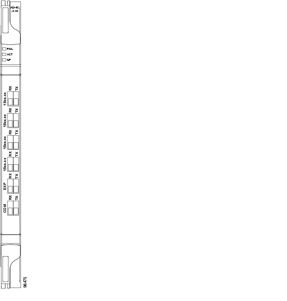
Figure 6-6 shows the AD-1C-xx.x faceplate.
Figure 6-6 AD-1C-xx.x Faceplate
For information on safety labels for the card, see the "Class 1M Laser Product Safety Lasers" section.
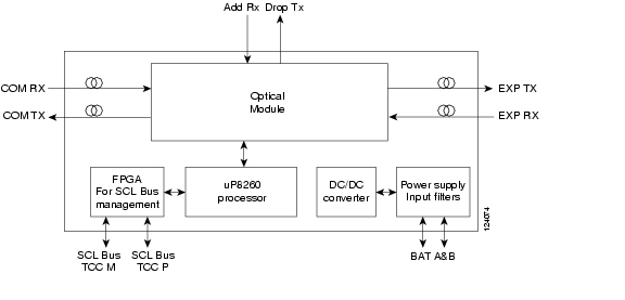
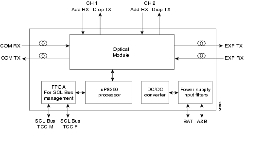
Figure 6-7 shows a block diagram of the AD-1C-xx.x card.
Figure 6-7 AD-1C-xx.x Block Diagram
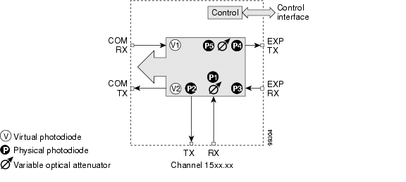
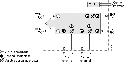
Figure 6-8 shows the AD-1C-xx.x optical module functional block diagram.
Figure 6-8 AD-1C-xx.x Optical Module Functional Block Diagram
6.3.1 Power Monitoring
Physical photodiodes P1 through P4 and virtual photodiodes V1 and V2 monitor the power for the AD-1C-xx.x card. The returned power level values are calibrated to the ports as shown in Table 6-7.
Table 6-7 AD-1C-xx.x Port Calibration
P1
ADD
COM TX
P2
DROP
DROP TX
P3
IN EXP
EXP RX
P4
OUT EXP
EXP TX
V1
IN COM
COM RX
V2
OUT COM
COM TX
6.3.2 AD-1C-xx.x Card-Level Indicators
The AD-1C-xx.x card has three card-level LED indicators, described in Table 6-8.
6.3.3 AD-1C-xx.x Port-Level Indicators
You can find the status of the card port using the LCD screen on the ONS 15454 fan-tray assembly. Use the LCD to view the status of any port or card slot; the screen displays the number and severity of alarms for a given port or slot. The AD-1C-xx.x has six LC-PC-II optical ports: two for add/drop channel client input and output, two for express channel input and output, and two for communication.
6.4 AD-2C-xx.x Card
Note
The 2-Channel OADM (AD-2C-xx.x) card passively adds or drops two adjacent 100-GHz channels within the same band. Sixteen versions of this card—each designed for use with one pair of wavelengths—are used in the ONS 15454 DWDM system. The card bidirectionally adds and drops in two different sections on the same card to manage signal flow in both directions. Each version of the card has a different part number.
The AD-2C-xx.x has the following features:
•
•
•
•
•
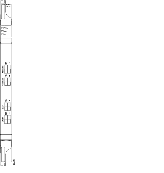
Figure 6-9 shows the AD-2C-xx.x faceplate.
Figure 6-9 AD-2C-xx.x Faceplate
For information on safety labels for the card, see the "Class 1M Laser Product Safety Lasers" section.
Figure 6-10 shows a block diagram of the AD-2C-xx.x card.
Figure 6-10 AD-2C-xx.x Block Diagram
Figure 6-11 shows the AD-2C-xx.x optical module functional block diagram.
Figure 6-11 AD-2C-xx.x Optical Module Functional Block Diagram
6.4.1 Wavelength Pairs
The AD-2C-xx.x cards are provisioned for the wavelength pairs listed in Table 6-9. In this table, channel IDs are given rather than wavelengths. To compare channel IDs with the actual wavelengths they represent, see wavelengths in Table 6-6.
6.4.2 Power Monitoring
Physical photodiodes P1 through P10 and virtual photodiodes V1 and V2 monitor the power for the AD-2C-xx.x card. The returned power level values are calibrated to the ports as shown in Table 6-10.
Table 6-10 AD-2C-xx.x Port Calibration
P1-P4
ADD
COM TX
P5-P8
DROP
DROP TX
P9
IN EXP
EXP RX
P10
OUT EXP
EXP TX
V1
IN COM
COM RX
V2
OUT COM
COM TX
6.4.3 AD-2C-xx.x Card-Level Indicators
The AD-2C-xx.x card has three card-level LED indicators, described in Table 6-11.
6.4.4 AD-2C-xx.x Port-Level Indicators
You can find the status of the card port using the LCD screen on the ONS 15454 fan-tray assembly. Use the LCD to view the status of any port or card slot; the screen displays the number and severity of alarms for a given port or slot. The AD-2C-xx.x card has eight LC-PC-II optical ports: four for add/drop channel client input and output, two for express channel input and output, and two for communication.
6.5 AD-4C-xx.x Card
Note
The 4-Channel OADM (AD-4C-xx.x) card passively adds or drops all four 100-GHz-spaced channels within the same band. Eight versions of this card—each designed for use with one band of wavelengths—are used in the ONS 15454 DWDM system. The card bidirectionally adds and drops in two different sections on the same card to manage signal flow in both directions. There are eight versions of this card with eight part numbers.
The AD-4C-xx.x has the following features:
•
•
•
•
•
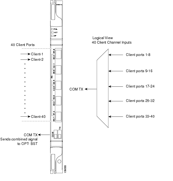
Figure 6-12 shows the AD-4C-xx.x faceplate.
Figure 6-12 AD-4C-xx.x Faceplate
For information on safety labels for the card, see the "Class 1M Laser Product Safety Lasers" section.
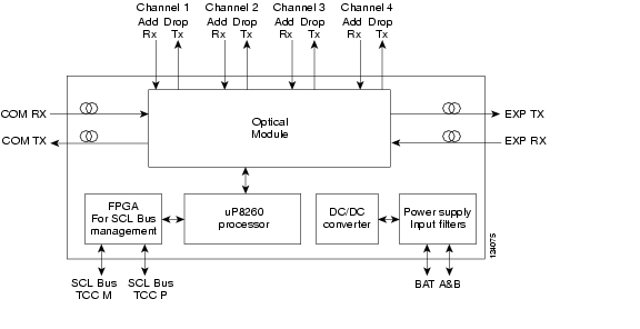
Figure 6-13 shows a block diagram of the AD-4C-xx.x card.
Figure 6-13 AD-4C-xx.x Block Diagram
Figure 6-14 shows the AD-4C-xx.x optical module functional block diagram.
Figure 6-14 AD-4C-xx.x Optical Module Functional Block Diagram
6.5.1 Wavelength Sets
The AD-4C-xx.x cards are provisioned for the sets of four 100-GHz-spaced wavelengths shown Table 6-12.
6.5.2 Power Monitoring
Physical photodiodes P1 through P10 and virtual photodiodes V1 and V2 monitor the power for the AD-4C-xx.x card. The returned power level values are calibrated to the ports as shown in Table 6-13.
Table 6-13 AD-4C-xx.x Port Calibration
P1-P4
ADD
COM TX
P5-P8
DROP
DROP TX
P9
IN EXP
EXP RX
P10
OUT EXP
EXP TX
V1
IN COM
COM RX
V2
OUT COM
COM TX
6.5.3 AD-4C-xx.x Card-Level Indicators
The AD-4C-xx.x card has three card-level LED indicators, described in Table 6-14.
6.5.4 AD-4C-xx.x Port-Level Indicators
You can find the status of the card port using the LCD screen on the ONS 15454 fan-tray assembly. Use the LCD to view the status of any port or card slot; the screen displays the number and severity of alarms for a given port or slot. The AD-4C-xx.x card has 12 LC-PC-II optical ports: eight for add/drop channel client input and output, two for express channel input and output, and two for communication.
6.6 AD-1B-xx.x Card
Note
The 1-Band OADM (AD-1B-xx.x) card passively adds or drops a single band of four adjacent 100-GHz-spaced channels. Eight versions of this card with eight different part numbers—each version designed for use with one band of wavelengths—are used in the ONS 15454 DWDM system. The card bidirectionally adds and drops in two different sections on the same card to manage signal flow in both directions. This card can be used when there is asymmetric adding and dropping on each side (east or west) of the node; a band can be added or dropped on one side but not on the other.
The AD-1B xx.x can be installed in Slots 1 to 6 and 12 to17 and has the following features:
•
•
•
•
•
•
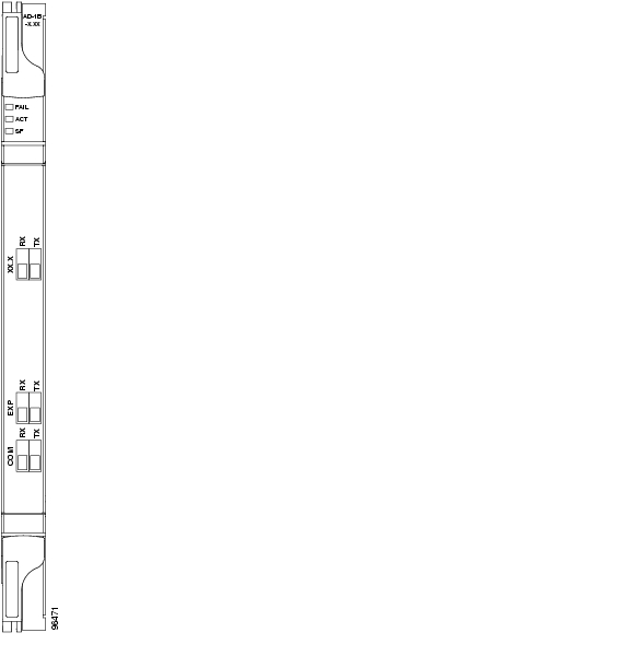
Figure 6-15 shows the AD-1B-xx.x faceplate.
Figure 6-15 AD-1B-xx.x Faceplate
For information on safety labels for the card, see the "Class 1M Laser Product Safety Lasers" section.
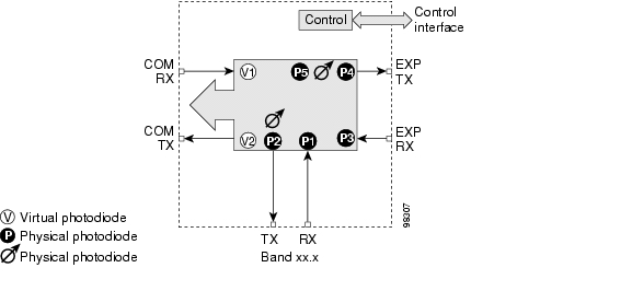
Figure 6-16 shows a block diagram of the AD-1B-xx.x card.
Figure 6-16 AD-1B-xx.x Block Diagram
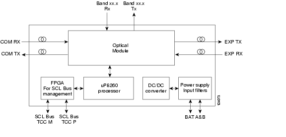
Figure 6-17 shows the AD-1B-xx.x optical module functional block diagram.
Figure 6-17 AD-1B-xx.x Optical Module Functional Block Diagram
6.6.1 Power Monitoring
Physical photodiodes P1 through P4 and virtual photodiodes V1 and V2 monitor the power for the AD-1B-xx.x card. The returned power level values are calibrated to the ports as shown in Table 6-15.
Table 6-15 AD-1B-xx.x Port Calibration
P1
ADD
BAND RX
P2
DROP
BAND TX
P3
IN EXP
EXP RX
P4
OUT EXP
EXP TX
V1
IN COM
COM RX
V2
OUT COM
COM TX
6.6.2 AD-1B-xx.x Card-Level Indicators
The AD-1B-xx.x card has three card-level LED indicators, described in Table 6-16.
6.6.3 AD-1B-xx.x Port-Level Indicators
You can find the status of the card port using the LCD screen on the ONS 15454 fan-tray assembly. Use the LCD to view the status of any port or card slot; the screen displays the number and severity of alarms for a given port or slot. The AD-1B-xx.x has six LC-PC-II optical ports: two for add/drop channel client input and output, two for express channel input and output, and two for communication.
6.7 AD-4B-xx.x Card
The 4-Band OADM (AD-4B-xx.x) card passively adds or drops four bands of four adjacent 100-GHz-spaced channels. Two versions of this card with different part numbers—each version designed for use with one set of bands—are used in the ONS 15454 DWDM system. The card bidirectionally adds and drops in two different sections on the same card to manage signal flow in both directions. This card can be used when there is asymmetric adding and dropping on each side (east or west) of the node; a band can be added or dropped on one side but not on the other.
The AD1B-xx.x can be installed in Slots 1 to 6 and 12 to 17 and has the following features:
•
•
•
•
•
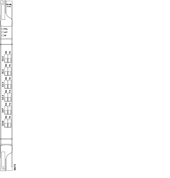
Figure 6-18 shows the AD-4B-xx.x faceplate.
Figure 6-18 AD-4B-xx.x Faceplate
For information on safety labels for the card, see the "Class 1M Laser Product Safety Lasers" section.
Figure 6-19 shows a block diagram of the AD-4B-xx.x card.
Figure 6-19 AD-4B-xx.x Block Diagram
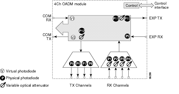
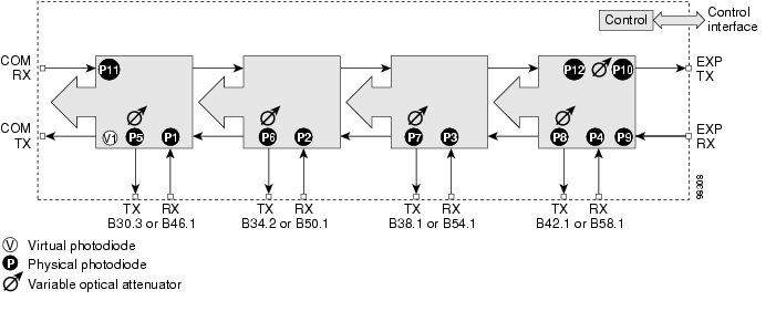
Figure 6-20 shows the AD-4B-xx.x optical module functional block diagram.
Figure 6-20 AD-4B-xx.x Optical Module Functional Block Diagram
6.7.1 Power Monitoring
Physical photodiodes P1 through P11 and virtual photodiode V1 monitor the power for the AD-4B-xx.x card. The returned power level values are calibrated to the ports as shown in Table 6-17.
Table 6-17 AD-4B-xx.x Port Calibration
P1-P4
ADD
COM TX
P5-P8
DROP
DROP TX
P9
IN EXP
EXP RX
P10
OUT EXP
EXP TX
P11
IN COM
COM RX
V1
OUT COM
COM TX
6.7.2 AD-4B-xx.x Card-Level Indicators
The AD-4B-xx.x card has three card-level LED indicators, described in Table 6-18.
6.7.3 AD-4B-xx.x Port-Level Indicators
You can find the status of the card port using the LCD screen on the ONS 15454 fan-tray assembly. Use the LCD to view the status of any port or card slot; the screen displays the number and severity of alarms for a given port or slot. The AD-4B-xx.x has 12 LC-PC-II optical ports: eight for add/drop band client input and output, two for express channel input and output, and two for communication.
![]()
![]()
![]()
![]()
![]()
![]()
![]()
![]()
Posted: Mon Oct 22 06:33:44 PDT 2007
All contents are Copyright © 1992--2007 Cisco Systems, Inc. All rights reserved.
Important Notices and Privacy Statement.