|
|

Table Of Contents
Reconfigurable Optical Add/Drop Cards
7.1.4 Channel Allocation Plans
7.2 Safety Labels for Class 1M Laser Product Cards
7.2.1 Class 1M Laser Product Label
7.2.3 Laser Source Connector Label
7.3.3 32WSS ROADM Functionality
7.3.5 32WSS Channel Allocation Plan
7.3.6 32WSS Card-Level Indicators
7.3.7 32WSS Port-Level Indicators
7.4.3 32WSS-L ROADM Functionality
7.4.4 32WSS-L Power Monitoring
7.4.6 32WSS-L Card-Level Indicators
7.5.3 32DMX ROADM Functionality
7.5.5 32DMX Channel Allocation Plan
7.5.6 32DMX Card-Level Indicators
7.5.7 32DMX Port-Level Indicators
7.6.3 32DMX-L ROADM Functionality
7.6.4 32DMX-L Power Monitoring
7.6.6 32DMX-L Card-Level Indicators
7.6.7 32DMX-L Port-Level Indicators
7.7.1 40-DMX-C Faceplate Ports
7.7.3 40-DMX-C ROADM Functionality
7.7.4 40-DMX-C Power Monitoring
7.7.6 40-DMX-C Card-Level Indicators
7.7.7 40-DMX-C Port-Level Indicators
7.8.1 40-MUX-C Faceplate Ports
7.8.3 40-MUX-C Power Monitoring
7.8.5 40-MUX-C Card-Level Indicators
7.8.6 40-MUX-C Port-Level Indicators
7.9.1 40-WSS-C Faceplate Ports
7.9.3 40-WSS-C ROADM Functionality
7.9.4 40-WSS-C Power Monitoring
7.9.6 40-WSS-C Card-Level Indicators
7.9.7 40-WSS-C Port-Level Indicators
7.10.1 40-WXC-C Faceplate Ports
7.10.3 40-WXC-C Power Monitoring
7.10.5 40-WXC-C Card-Level Indicators
7.10.6 40-WXC-C Port-Level Indicators
7.11.4 MMU Card-Level Indicators
7.11.5 MMU Port-Level Indicators
Reconfigurable Optical Add/Drop Cards
This chapter describes the Cisco ONS 15454 cards deployed in reconfigurable optical add/drop (ROADM) networks. For installation and card turn-up procedures, refer to the Cisco ONS 15454 DWDM Procedure Guide. For card safety and compliance information, refer to the Cisco Optical Transport Products Safety and Compliance Information document.
Note
Unless otherwise specified, "ONS 15454" refers to both ANSI and ETSI shelf assemblies.
Chapter topics include:
•
•
Note
7.1 Card Overview
The ROADM cards include six add drop cards utilized in the C band (32WSS, 32DMX, 32DMX-C, 40-MUX-C, 40-WXC-C, and MMU) and two add drop cards utilized for the L band (32WSS-L, and 32DMX-L).
This section provides card summary, compatibility, channel allocation, and safety information.
Note
7.1.1 Card Summary
Table 7-1 lists and summarizes information about each ROADM card.
Table 7-1 ROADM Card Summary
The 32WSS card has seven sets of ports located on the faceplate. It operates in Slots 1 to 5 and 12 to 16.
See the "32WSS Card" section
The 32WSS-L card has seven sets of ports located on the faceplate. It operates in Slots 1 to 5 and 12 to 16.
See the "32WSS-L Card" section
The 32DMX has five sets of ports located on the faceplate. It operates in Slots 1 to 6 and 12 to 17.
See the "32DMX Card" section
The 32DMX-L has five sets of ports located on the faceplate. It operates in Slots 1 to 6 and 12 to 17.
See the "32DMX-L Card" section
The 40-DMX-C has six sets of ports located on the faceplate. It operates in Slots 1 to 6 and 12 to 17.
See the "40-DMX-C Card" section
The 40-MUX-C has six sets of ports located on the faceplate. It operates in Slots 1 to 6 and 12 to 17.
See the "40-MUX-C Card" section.
The 40-WSS-C card has eight sets of ports located on the faceplate. It operates in Slots 1 to 5 and 12 to 16.
See the "40-WSS-C Card" section
The 40-WXC-C card has five sets of ports located on the faceplate. It operates in Slots 1 to 5 and 12 to 16.
See the "40-WXC-C Card" section
The MMU card has six sets of ports located on the faceplate, It operates in Slots 1 to 6 and 12 to 17.
See the "MMU Card" section
7.1.2 Card Compatibility
Table 7-2 lists the Cisco Transport Controller (CTC) software compatibility for the ROADM cards.
7.1.3 Interface Classes
The 40-MUX-C, 32DMX, 32DMX-L, 40-DMX-C, 32WSS, and 32WSS-L cards have different input and output optical channel signals depending on the interface card originating the input signal. The input interface cards have been grouped in classes listed in Table 7-3. The subsequent tables list the optical performance and output power of each interface class.
Table 7-4 lists the optical performance parameters for the following 10-Gbps cards that provide signal to the following multiplexer cards and demultiplexer cards:
•
•
•
•
•
•
•
•
•
Table 7-4 10-Gbps Interface Optical Performance
Maximum bit rate
10 Gbps
10 Gbps
10 Gbps
10 Gbps
Regeneration
3R
3R
3R
3R
FEC
Yes
No
No
Yes (E-FEC)
Threshold
Optimum
Average
Average
Optimum
Maximum BER2
10-15
10-12
10-12
10-15
OSNR 1 sensitivity
23 dB
9 dB
23 dB
19 dB
19 dB
20 dB
8 dB
Power sensitivity
-24 dBm
-18 dBm
-21 dBm
-20 dBm
-22 dBm
-26 dBm
-18 dBm
Power overload
-8 dBm
-8 dBm
-9 dBm
-8 dBm
Transmitted Power Range3
10-Gbps multirate transponder/10-Gbps FEC transponder (TXP_MR_10G)
+2.5 to 3.5 dBm
+2.5 to 3.5 dBm
—
—
OC-192 LR ITU
—
—
+3.0 to 6.0 dBm
—
10-Gbps multirate transponder/10-Gbps FEC transponder (TXP_MR_10E)
+3.0 to 6.0 dBm
+3.0 to 6.0 dBm
—
+3.0 to 6.0 dBm
Dispersion compensation tolerance
+/-800 ps/nm
+/-1,000 ps/nm
+/-1,000 ps/nm
+/-800 ps/nm
1 OSNR = optical signal-to-noise ratio
2 BER = bit error rate
3 These values, decreased by patchcord and connector losses, are also the input power values for the optical add drop multiplexer (OADM) cards.
•
•
•
•
•
•
•
•
•
•
Table 7-5 2.5-Gbps Interface Optical Performance
Maximum bit rate
2.5 Gbps
2.5 Gbps
2.5 Gbps
2.5 Gbps
1.25 Gbps
2.5 Gbps
Regeneration
3R
3R
2R
3R
3R
3R
FEC
Yes
No
No
No
No
No
Threshold
Average
Average
Average
Average
Average
Average
Maximum BER
10-15
10-12
10-12
10-12
10-12
10-12
OSNR sensitivity
14 dB
6 dB
14 dB
10 dB
15 dB
14 dB
11 dB
13 dB
8 dB
12 dB
Power sensitivity
-31 dBm
-25 dBm
-30 dBm
-23 dBm
-24 dBm
-27 dBm
-33 dBm
-28 dBm
-18 dBm
-26 dBm
Power overload
-9 dBm
-9 dBm
-9 dBm
-9 dBm
-7 dBm
-17dBm
Transmitted Power Range1
TXP_MR_2.5G
-1.0 to 1.0 dBm
-1.0 to 1.0 dBm
-1.0 to 1.0 dBm
-2.0 to 0 dBm
—
—
TXPP_MR_2.5G
-4.5 to -2.5 dBm
-4.5 to -2.5 dBm
-4.5 to -2.5 dBm
MXP_MR_2.5G
—
+2.0 to +4.0 dBm
—
MXPP_MR_2.5G
—
-1.5 to +0.5 dBm
—
2/4 port GbE Transponder (GBIC WDM 100GHz)
—
—
—
—
+2.5 to 3.5 dBm
—
Dispersion compensation tolerance
-1200 to +5400 ps/nm
-1200 to +5400 ps/nm
-1200 to +3300 ps/nm
-1200 to +3300 ps/nm
-1000 to +3600 ps/nm
-1000 to +3200 ps/nm
1 These values, decreased by patchcord and connector losses, are also the input power values for the OADM cards.
7.1.4 Channel Allocation Plans
ONS 15454 DWDM ROADM cards are designed for use with specific channels in the C band and L band. In most cases, the channels for these cards are either numbered (for example, 1 to 32 or 1 to 40) or delimited (odd or even). Client interfaces must comply with these channel assignments to be compatible with the ONS 15454 system.
. The following cards operate in the C band:
•
•
•
•
•
•
Table 7-6 lists the C band channel IDs and wavelengths at ITU-T 50-GHz intervals. This is a comprehensive C band channel table that encompasses future card capability as well as present capabilities.
.
Table 7-6 DWDM C1 Band Channel Allocation Plan with 50-GHz Spacing
0
196.00
1529.55
41
193.95
1545.72
1
195.95
1529.94
42
193.90
1546.119
2
195.90
1530.334
43
193.85
1546.518
3
195.85
1530.725
44
193.80
1546.917
4
195.80
1531.116
45
193.75
1547.316
5
195.75
1531.507
46
193.70
1547.715
6
195.70
1531.898
47
193.65
1548.115
7
195.65
1532.290
48
193.60
1548.515
8
195.60
1532.681
49
193.55
1548.915
9
195.55
1533.073
50
193.50
1549.32
10
195.50
1533.47
51
193.45
1549.71
11
195.45
1533.86
52
193.40
1550.116
12
195.40
1534.250
53
193.35
1550.517
13
195.35
1534.643
54
193.30
1550.918
14
195.30
1535.036
55
193.25
1551.319
15
195.25
1535.429
56
193.20
1551.721
16
195.20
1535.822
57
193.15
1552.122
17
195.15
1536.216
58
193.10
1552.524
18
195.10
1536.609
59
193.05
1552.926
19
195.05
1537.003
60
193.00
1553.33
20
195.00
1537.40
61
192.95
1553.73
21
194.95
1537.79
62
192.90
1554.134
22
194.90
1538.186
63
192.85
1554.537
23
194.85
1538.581
64
192.80
1554.940
24
194.80
1538.976
65
192.75
1555.343
25
194.75
1539.371
66
192.70
1555.747
26
194.70
1539.766
67
192.65
1556.151
27
194.65
1540.162
68
192.60
1556.555
28
194.60
1540.557
69
192.55
1556.959
29
194.55
1540.953
70
192.50
1557.36
30
194.50
1541.35
71
192.45
1557.77
31
194.45
1541.75
72
192.40
1558.173
32
194.40
1542.142
73
192.35
1558.578
33
194.35
1542.539
74
192.30
1558.983
34
194.30
1542.936
75
192.25
1559.389
35
194.25
1543.333
76
192.20
1559.794
36
194.20
1543.730
77
192.15
1560.200
37
194.15
1544.128
78
192.10
1560.606
38
194.10
1544.526
79
192.05
1561.013
39
194.05
1544.924
80
192.00
1561.42
40
194.00
1545.32
81
191.95
1561.83
1 Channels on the C band are 4-skip-1, starting at 1530.33 nm.
The following add drop cards utilize the L band DWDM channels:
•
•
Table 7-7 lists the L band channel IDs and wavelengths at ITU-T 50-GHz intervals. This is a comprehensive L band channel table that encompasses future card capability as well as present capabilities.
Table 7-7 DWDM L Band1 Channel Allocation Plan at 50 GHz Spacing
1
190.85
1570.83
41
188.85
1587.46
2
190.8
1571.24
42
188.8
1587.88
3
190.75
1571.65
43
188.75
1588.30
4
190.7
1572.06
44
188.7
1588.73
5
190.65
1572.48
45
188.65
1589.15
6
190.6
1572.89
46
188.6
1589.57
7
190.55
1573.30
47
188.55
1589.99
8
190.5
1573.71
48
188.5
1590.41
9
190.45
1574.13
49
188.45
1590.83
10
190.4
1574.54
50
188.4
1591.26
11
190.35
1574.95
51
188.35
1591.68
12
190.3
1575.37
52
188.3
1592.10
13
190.25
1575.78
53
188.25
1592.52
14
190.2
1576.20
54
188.2
1592.95
15
190.15
1576.61
55
188.15
1593.37
16
190.1
1577.03
56
188.1
1593.79
17
190.05
1577.44
57
188.05
1594.22
18
190
1577.86
58
188
1594.64
19
189.95
1578.27
59
187.95
1595.06
20
189.9
1578.69
60
187.9
1595.49
21
189.85
1579.10
61
187.85
1595.91
22
189.8
1579.52
62
187.8
1596.34
23
189.75
1579.93
63
187.75
1596.76
24
189.7
1580.35
64
187.7
1597.19
25
189.65
1580.77
65
187.65
1597.62
26
189.6
1581.18
66
187.6
1598.04
27
189.55
1581.60
67
187.55
1598.47
28
189.5
1582.02
68
187.5
1598.89
29
189.45
1582.44
69
187.45
1599.32
30
189.4
1582.85
70
187.4
1599.75
31
189.35
1583.27
71
187.35
1600.17
32
189.3
1583.69
72
187.3
1600.60
33
189.25
1584.11
73
187.25
1601.03
34
189.2
1584.53
74
187.2
1601.46
35
189.15
1584.95
75
187.15
1601.88
36
189.1
1585.36
76
187.1
1602.31
37
189.05
1585.78
77
187.05
1602.74
38
189
1586.20
78
187
1603.17
39
188.95
1586.62
79
186.95
1603.60
40
188.9
1587.04
80
186.9
1604.03
1 Channels on the L band are contiguous, starting at 1577.86 nm. The channels listed in this table begin with 1570.83 nm for backward compatibility with other ONS products.
7.2 Safety Labels for Class 1M Laser Product Cards
This section explains the significance of the safety labels attached to some of the cards. The card faceplates are clearly labeled with warnings about the laser radiation levels. You must understand all warning labels before working on these cards.
The 32DMX, 32DMX-L, 40-MUX-C, 40-DMX-C, 32WSS, 32WSS-L, 40-WSS-C, and 40-WXC-C cards have Class IM lasers. The labels that appear on these cards are described in the following subsections.
7.2.1 Class 1M Laser Product Label
Figure 7-1 shows the Class 1M Laser Product label.
Figure 7-1 Class 1M Laser Product Label
Class 1M lasers are products that produce either a highly divergent beam or a large diameter beam. Therefore, only a small part of the whole laser beam can enter the eye. However, these laser products can be harmful to the eye if the beam is viewed using magnifying optical instruments.
7.2.2 Hazard Level 1M Label
Figure 7-2 shows the Hazard Level 1M label. The Hazard Level label warns users against exposure to laser radiation by Class 1 limits calculated in accordance with IEC60825-1 Ed.1.2.
Figure 7-2 Hazard Level Label
7.2.3 Laser Source Connector Label
Figure 7-3 shows the Laser Source Connector label. This label indicates that a laser source is present at the optical connector where the label is located.
Figure 7-3 Laser Source Connector Label
7.2.4 FDA Statement Label
Figure 7-4 shows the FDA Statement label. This label shows compliance to FDA standards and indicates that the hazard level classification is in accordance with IEC60825-1 Am.2 or Ed.1.2.
Figure 7-4 FDA Statement Label
7.2.5 Shock Hazard Label
Figure 7-5 shows the Shock Hazard label. This label alerts you to electrical hazards within a card. A shock hazard exists when you remove adjacent cards during maintenance, or when you touch exposed electrical circuitry on the card itself.
Figure 7-5 Shock Hazard Label
7.3 32WSS Card
Note
Note
The two-slot 32-Channel Wavelength Selective Switch (32WSS) card performs channel add/drop processing within the ONS 15454 DWDM node. The 32WSS card can be installed in the following pairs of slots:
•
•
•
•
•
•
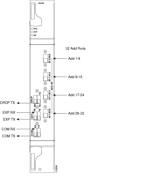
7.3.1 32WSS Faceplate Ports
The 32WSS has six types of ports:
•
•
•
•
•
•
Figure 7-6 shows the 32WSS card front panel and identifies the traffic flow through the ports.
Figure 7-6 32WSS Faceplate and Ports
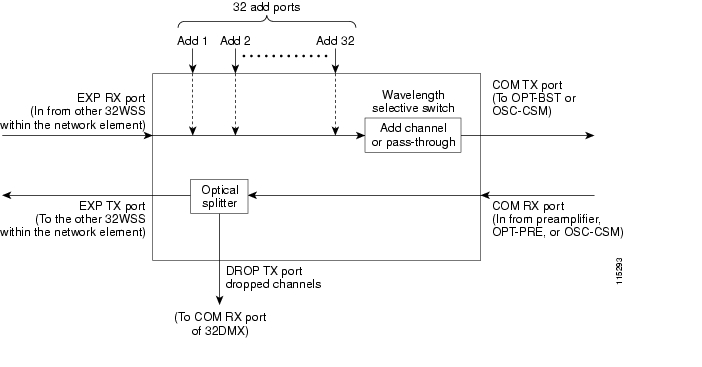
7.3.2 32WSS Block Diagram
Figure 7-7 provides a high-level functional block diagram of the 32WSS card and Figure 7-8 shows how optical signals are processed on the EXP RX and COM RX ports.
Figure 7-7 32WSS Block Diagram
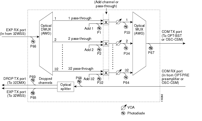
Aggregate optical signals that enter the EXP RX and COM RX port are processed in two ways: Add channel/pass-through and optical splitter processing. The optical processing stages are shown in Figure 7-8, which provides a detailed optical functional diagram of the 32WSS card.
Figure 7-8 32WSS Optical Block Diagram
The EXP RX PORT and COM RX PORT operate as follows:
•
The incoming optical signal is received at the EXP RX port from the other 32WSS card within the NE. The incoming aggregate optical signal is demultiplexed into 32 individual wavelengths, or channels. Each channel is then individually processed by the optical switch, which performs add/pass-through processing. By using software controls, the switch either selects the optical channel coming in from the demultiplexer (that is, the pass-through channel) or it selects the external ADD channel. If the ADD port channel is selected this channel is transmitted and the optical signal coming from the demultiplexer is blocked.
After the optical switch stage, all of the channels are multiplexed into an aggregate optical signal, which is sent out on the COM TX port. The output is typically connected to an OPT-BST or OPT-BST-E card (in the event a booster amplifier is needed) or to an OSC-CSM card (if no amplification is needed).
•
The COM RX port receives the incoming optical signal and directs it to the 32WSS card's optical splitter. The splitter optically diverts channels that are designated to be dropped to the DROP TX port. The DROP TX port is typically connected to the COM RX port of the 32DMX where the drop channels are being dropped. Channels that are not dropped pass through the optical splitter and flow out of the 32WSS card EXP TX port. Typically, this optical signal is connected to the other 32WSS module within the NE.
7.3.3 32WSS ROADM Functionality
The 32WSS card works in combination with the 32DMX card to implement ROADM functionality. As a ROADM node, the ONS 15454 can be configured to add or drop individual optical channels using CTC, Cisco MetroPlanner, and Cisco Transport Manager (CTM). ROADM functionality using the 32WSS card requires two 32DMX single-slot cards and two 32WSS double-slot cards (totalling six slots needed in the ONS 15454 chassis).
For other cards' ROADM functionality, see that card's description in this chapter. For a diagram of a typical ROADM configuration, see the "ROADM Node" section.
Note
7.3.4 32WSS Power Monitoring
Physical photodiodes P1 through P69 monitor the power for the 32WSS card. Table 7-8 shows how the returned power level values are calibrated to each port.
Table 7-8 32WSS Port Calibration
P1-P32
ADD (Power ADD)
ADD RX
P33-P641
PASS THROUGH
COM TX
ADD (Power)
COM TX
P65
OUT EXP
EXP TX
P66
IN EXP
EXP RX
P67
OUT COM
COM TX
P68
IN COM
COM RX
P69
DROP
DROP TX
1 P33-P64 monitor either ADD or PASSTHROUGH power, depending on the state of the optical switch
7.3.5 32WSS Channel Allocation Plan
The 32WSS Card's channel labels, frequencies, and wavelengths are listed in Table 7-9.
7.3.6 32WSS Card-Level Indicators
Table 7-10 describes the three card-level LED indicators on the 32WSS card.
7.3.7 32WSS Port-Level Indicators
You can find the alarm status of the 32WSS card's ports using the LCD screen on the ONS 15454 fan-tray assembly. The screen displays the number and severity of alarms on a given port or slot. For the procedure to view these counts, refer to "Manage Alarms" in the Cisco ONS 15454 DWDM Procedure Guide.
7.4 32WSS-L Card
Note
Note
The two-slot 32-Channel Wavelength Selective Switch L-Band (32WSS-L) card performs channel add/drop processing within the ONS 15454 DWDM node. The 32WSS-L card is particularly well suited for use in networks that employ DS fiber or SMF-28 single-mode fiber.The 32WSS-L card can be installed in the following pairs of slots:
•
•
•
•
•
•
7.4.1 32WSS-L Faceplate Ports
The 32WSS-L card faceplate has six types of ports:
•
•
•
•
•
•
Figure 7-9 shows the 32WSS-L module front panel and identifies the traffic flow through the ports.
Figure 7-9 32WSS-L Faceplate and Ports
7.4.2 32WSS-L Block Diagram
Figure 7-10 provides a high-level functional block diagram of the 32WSS-L card and Figure 7-11 shows how optical signals are processed on the EXP RX and COM RX ports.
Figure 7-10 32WSS-L Block Diagram
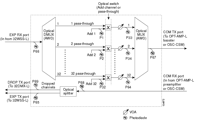
Aggregate optical signals that enter the EXP RX and COM RX ports are processed in two ways: add channel/pass-through and optical splitter processing. The optical processing stages are shown in Figure 7-11, which provides a detailed optical functional diagram of the 32WSS-L card.
Figure 7-11 32WSS-L Optical Block Diagram
The EXP RX PORT and COM RX PORT operate as follows:
•
The incoming optical signal is received at the EXP RX port from the other 32WSS-L card within the NE. The incoming aggregate optical signal is demultiplexed into 32 individual wavelengths, or channels. Each channel is then individually processed by the optical switch, which performs add/pass-through processing. By using software controls, the switch either selects the optical channel coming in from the demultiplexer (that is, the pass-through channel) or it selects the external ADD channel. If the ADD port channel is selected this channel is transmitted and the optical signal coming from the demultiplexer is blocked.
After the optical switch stage, all of the channels are multiplexed into an aggregate optical signal, which is sent out on the COM TX port. The output is typically connected to an OPT-AMP-L or OPT-BST-E card (in the event a booster amplifier is needed) or to an OSC-CSM card (if no amplification is needed).
•
The COM RX port receives the incoming optical signal and directs it to the 32WSS-L card's optical splitter. The splitter optically diverts channels that are designated to be dropped to the DROP TX port. The DROP TX port is typically connected to the COM RX port of the 32DMX-L where the drop channels are being dropped. Channels that are not dropped pass through the optical splitter and flow out of the 32WSS-L card EXP TX port. Typically, this optical signal is connected to the other 32WS-L module within the NE.
7.4.3 32WSS-L ROADM Functionality
The 32WSS-L works in combination with the 32DMX-L to implement L band (1570 to 1620 nm) functionality. As a ROADM node, the ONS 15454 can be configured to add or drop individual optical channels using CTC, Cisco MetroPlanner, and CTM. ROADM functionality using the 32WSS-L card requires two 32DMX-L single-slot cards and two 32WSS-L double-slot cards (totalling six slots needed in the ONS 15454 chassis).
For other cards' ROADM functionality, see that card's description in this chapter. For a diagram of a typical ROADM configuration, see the "ROADM Node" section.
Note
7.4.4 32WSS-L Power Monitoring
Physical photodiodes P1 through P69 monitor the power for the 32WSS-L card. Table 7-11 shows the returned power level values calibrated to each port.
Table 7-11 32WSS-L Port Calibration
P1-P32
ADD (Power ADD)
ADD RX
P33-P641
PASS THROUGH
COM TX
ADD (Power)
COM TX
P65
OUT EXP
EXP TX
P66
IN EXP
EXP RX
P67
OUT COM
COM TX
P68
IN COM
COM RX
P69
DROP
DROP TX
1 P33-P64 monitor either ADD or PASSTHROUGH power, depending on the state of the optical switch
7.4.5 32WSS-L Channel Plan
The 32WSS-L card uses 32 banded channels on the ITU-T 100-GHz grid, as shown in Table 7-12.
7.4.6 32WSS-L Card-Level Indicators
Table 7-13 describes the three card-level LED indicators on the 32WSS-L card.
7.5 32DMX Card
Note
Note
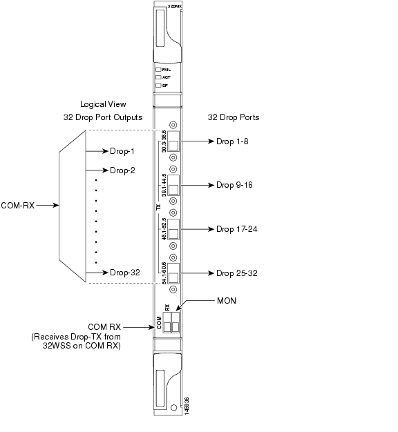
The single-slot 32-Channel Demultiplexer (32DMX) card is an optical demultiplexer. The card receives an aggregate optical signal on its COM RX port and demultiplexes it into to (32) ITU-T 100-GHz-spaced channels. The 32DMX card can be installed in Slots 1 to 6 and in Slots 12 to 17.
7.5.1 32DMX Faceplate Ports
The 32DMX card has two types of ports:
•
•
Figure 7-12 shows the 32DMX card front panel and the basic traffic flow through the ports.
Figure 7-12 32DMX Faceplate and Ports
7.5.2 32DMX Block Diagram
A block diagram of the 32DMX card is shown in Figure 7-13.
Figure 7-13 32DMX Block Diagram
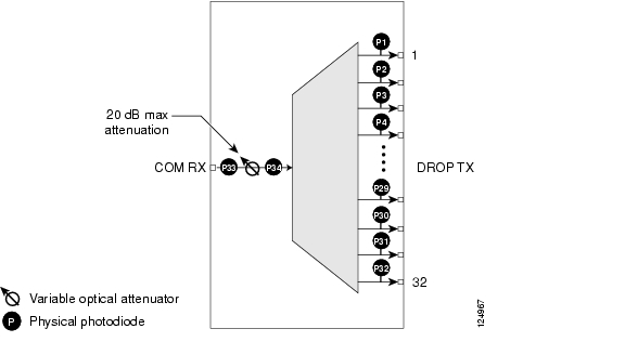
Figure 7-14 shows the 32DMX optical module functional block diagram.
Figure 7-14 32DMX Optical Module Functional Block Diagram
7.5.3 32DMX ROADM Functionality
The 32DMX card works in combination with the 32WSS card to implement ROADM functionality. As a ROADM node, the ONS 15454 can be configured to add or drop individual optical channels using CTC, Cisco MetroPlanner, and CTM. ROADM functionality using the 32DMX card requires two 32DMX single-slot cards and two 32WSS double-slot cards (for six slots total in the ONS 15454 chassis).
For information about the ROADM functionality for other cards, see that card's description in this chapter. For a diagram of a typical ROADM configuration, see the "ROADM Node" section.
Note
7.5.4 32DMX Power Monitoring
Physical photodiodes P1 through P33 monitor the power for the 32DMX card. The returned power level values are calibrated to the ports as shown in Table 7-14.
Table 7-14 32DMX Port Calibration
P1-P32
DROP
DROP TX
P33
INPUT COM
COM RX
7.5.5 32DMX Channel Allocation Plan
The 32DMX card's channel labels, frequencies, and wavelengths are listed in Table 7-15.
7.5.6 32DMX Card-Level Indicators
Table 7-16 describes the three card-level LED indicators on the 32DMX card.
7.5.7 32DMX Port-Level Indicators
You can find the alarm status of the 32DMX card's ports using the LCD screen on the ONS 15454 fan-tray assembly. The screen displays the number and severity of alarms on a given port or slot. For the procedure to view these counts, refer to "Manage Alarms" in the Cisco ONS 15454 DWDM Procedure Guide.
7.6 32DMX-L Card
Note
Note
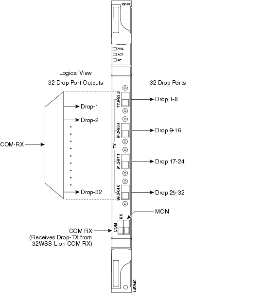
The single-slot 32-Channel Demultiplexer L-Band card (32DMX-L) is an L band optical demultiplexer. The card receives an aggregate optical signal on its COM RX port and demultiplexes it into to (32) 100-GHz-spaced channels. The 32DMX-L card is particularly well suited for use in networks that employ DS fiber or SMF-28 single-mode fiber. The 32DMX-L card can be installed in Slots 1 to 6 and in Slots 12 to 17.
7.6.1 32DMX-L Faceplate Ports
The 32DMX-L card has two types of ports:
•
•
Figure 7-15 shows the 32DMX-L card front panel and the basic traffic flow through the ports.
Figure 7-15 32DMX-L Faceplate and Ports
7.6.2 32DMX-L Block Diagram
Figure 7-16 shows a block diagram of the 32DMX-L card.
Figure 7-16 32DMX-L Block Diagram
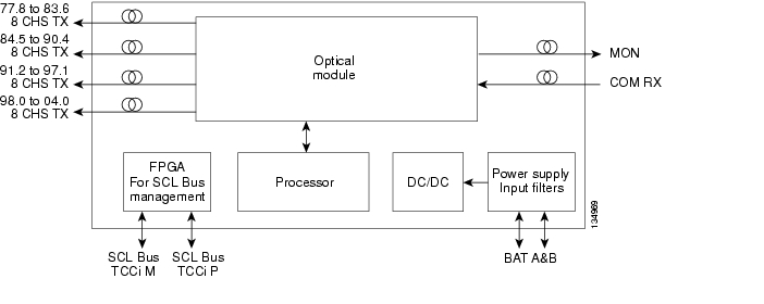
Figure 7-17 shows the 32DMX-L optical module functional block diagram.
Figure 7-17 32DMX-L Optical Module Functional Block Diagram
7.6.3 32DMX-L ROADM Functionality
The 32DMX-L card works in combination with the 32WSS-L card to implement ROADM functionality. AS a ROADM node, the ONS 15454 can be configured to add or drop individual optical channels using CTC, Cisco MetroPlanner, and CTM. ROADM functionality using the 32DMX-L card requires two 32DMX-L single-slot cards and two 32WSS-L double-slot cards (for a total of six slots in the ONS 15454 chassis).
For information about ROADM functionality for other cards, see that card's description in this chapter. For a diagram of a typical ROADM configuration, see the "ROADM Node" section.
Note
7.6.4 32DMX-L Power Monitoring
Physical photodiodes P1 through P33 monitor the power for the 32DMX-L card. The returned power level values are calibrated to the ports as shown in Table 7-17.
Table 7-17 32DMX-L Port Calibration
P1-P32
DROP
DROP TX
P33
INPUT COM
COM RX
7.6.5 32DMX-L Channel Plan
The 32DMX-L card uses 32 banded channels on the ITU-T 100-GHz grid, as shown in Table 7-18.
7.6.6 32DMX-L Card-Level Indicators
Table 7-19 describes the three card-level LED indicators on the 32DMX-L card.
7.6.7 32DMX-L Port-Level Indicators
You can find the alarm status of the 32DMX-L card's ports using the LCD screen on the ONS 15454 fan-tray assembly. The screen displays the number and severity of alarms on a given port or slot. For the procedure to view these counts, refer to "Manage Alarms" in the Cisco ONS 15454 DWDM Procedure Guide.
7.7 40-DMX-C Card
Note
Note
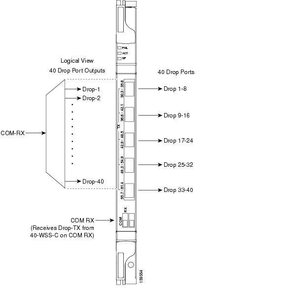
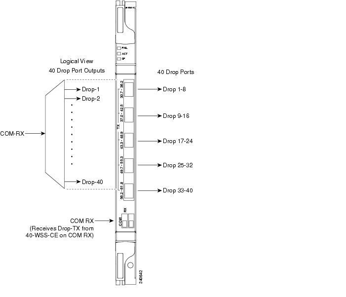
The single-slot 40-Channel Demultiplexer C-band (40-DMX-C) card demultiplexes 40 100-GHz-spaced channels identified in the channel plan ( Table 7-21), and sends them to dedicated output ports. The overall optical power can be adjusted using a single VOA that is common to all channels. The 40-DMX-C card is unidirectional, optically passive, and can be installed in Slots 1 to 6 and 12 to 17.
7.7.1 40-DMX-C Faceplate Ports
The 40-DMX-C has two types of ports:
•
Note
•
Figure 7-18 shows the 40-DMX-C card faceplate.
Figure 7-18 40-DMX-C Faceplate
7.7.2 40-DMX-C Block Diagram
Figure 7-19 shows a block diagram of the 40-DMX-C card.
Figure 7-19 40-DMX-C Block Diagram
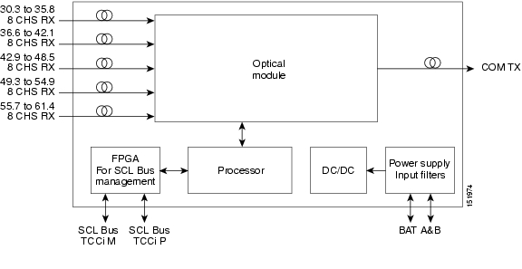
Figure 7-20 shows the 40-DMX-C optical module functional block diagram.
Figure 7-20 40-DMX-C Optical Module Functional Block Diagram
7.7.3 40-DMX-C ROADM Functionality
The 40-DMX-C card works in combination with the 40-WSS-C card to implement ROADM functionality. As a ROADM node, the ONS 15454 can be configured at the optical channel level using CTC, Cisco MetroPlanner, and CTM. ROADM functionality using the 40-DMX-C card requires two single-slot 40-DMX-C cards and two 40-WSS-C double-slot cards (for a total of six slots in the ONS 15454 chassis).
For other cards' ROADM functionality, see that card's description in this chapter. For a diagram of a typical ROADM configuration, see the "ROADM Node" section.
7.7.4 40-DMX-C Power Monitoring
Physical photodiodes P1 through P40 monitor the power at the outputs of the 40-DMX-C card. P41 monitors the total multiplexed power at the input, calibrated to the COM-RX port. Table 7-20 shows the returned power level values calibrated to each port.
Table 7-20 40-DMX-C Port Calibration
P1-P40
DROP
DROP TX
P41
INPUT COM
COM RX
7.7.5 40-DMX-C Channel Plan
Table 7-21 shows the 40 ITU-T 100-GHz-spaced, C band channels (wavelengths) that are demultiplexed by the 40-DMX-C card.
7.7.6 40-DMX-C Card-Level Indicators
The 40-DMX-C card has three card-level LED indicators, described in Table 7-22.
7.7.7 40-DMX-C Port-Level Indicators
You can find the alarm status of the 40-DMX-C card ports using the LCD screen on the ONS 15454 fan-tray assembly. The screen displays the number and severity of alarms on a given port or slot. For the procedure to view these counts, refer to "Manage Alarms" in the Cisco ONS 15454 DWDM Procedure Guide.
7.8 40-MUX-C Card
Note
Note
The single-slot 40-Channel Multiplexer C-band (40-MUX-C) card multiplexes forty ITU-T 100-GHz-spaced channels identified in the channel plan in Table 7-21. The 40-MUX-C card can be installed in Slots 1 to 6 and 12 to 17. The 40-MUX-C card is typically used in hub nodes.
7.8.1 40-MUX-C Faceplate Ports
The 40-MUX-C has two types of ports:
•
Note
•
Figure 7-21 shows the 40-MUX-C card faceplate.
Figure 7-21 40-MUX-C Card Faceplate
7.8.2 40-MUX-C Block Diagram
Figure 7-22 shows a block diagram of the 40-MUX-C card.
Figure 7-22 40-MUX-C Block Diagram
Figure 7-23 shows the 40-MUX-C optical module functional block diagram.
Figure 7-23 40-MUX-C Optical Module Functional Block Diagram
7.8.3 40-MUX-C Power Monitoring
Physical photodiodes P1 through P40 monitor the power of the individual input ports to the 40-MUX-C card. P41 monitors the total multiplexed output power, calibrated to the COM-TX port. Table 7-23 shows the returned power level values calibrated to each port.
Table 7-23 40-MUX-C Port Calibration
P1-P40
ADD
ADD RX
P41
OUTPUT COM
COM-TX
7.8.4 40-MUX-C Channel Plan
Table 7-24 shows the 40 ITU-T 100-GHz-spaced, C band channels (wavelengths) that are multiplexed by the 40-MUX-C card.
7.8.5 40-MUX-C Card-Level Indicators
The 40-MUX-C card has three card-level LED indicators, described in Table 7-25.
7.8.6 40-MUX-C Port-Level Indicators
You can find the alarm status of the 40-MUX-C card ports using the LCD screen on the ONS 15454 fan-tray assembly. The screen displays the number and severity of alarms on a given port or slot. For the procedure to view these counts, refer to "Manage Alarms" in the Cisco ONS 15454 DWDM Procedure Guide.
7.9 40-WSS-C Card
Note
Note
The double-slot 40-channel Wavelength Selective Switch C-Band (40-WSS-C) card switches 40 ITU-T 100-GHz-spaced channels identified in the channel plan ( Table 7-21) and sends them to dedicated output ports. The 40-WSS-C card is bidirectional and optically passive. The card can be installed in Slots 1 to 6 and 12 to 17
The 40-WSS-C features include:
•
•
•
•
Within the 40-WSS-C card, the first AWG opens the spectrum and each wavelength is directed to one of the ports of a 1x2 optical switch. The same wavelength can be passed through or stopped. If the pass-through wavelength is stopped, a new channel can be added at the ADD port. The card's second AWG multiplexes all of the wavelengths, and the aggregate signal is output through the COM-TX port.
7.9.1 40-WSS-C Faceplate Ports
The 40-WSS-C has eight types of ports:
•
•
•
•
•
•
Figure 7-24 shows the 40-WSS-C card faceplate.
Figure 7-24 40-WSS-C Faceplate
7.9.2 40-WSS-C Block Diagram
Figure 7-25 shows a block diagram of the 40-WSS-C card.
Figure 7-25 40-WSS-C Block Diagram
Figure 7-26 shows the 40-WSS-C optical module functional block diagram.
Figure 7-26 40-WSS-C Optical Module Functional Block Diagram
7.9.3 40-WSS-C ROADM Functionality
The 40-WSS-C card works in combination with the 40-DMX-C card to implement ROADM functionality. As a ROADM node, the ONS 15454 can be configured at the optical channel level using CTC, Cisco MetroPlanner, and CTM. ROADM functionality using the 40-WSS-C card requires two 40-WSS-C double-slot cards and two 40-DMX-C single-slot cards (for a total of six slots in the ONS 15454 chassis).
For information about ROADM functionality for other cards, see that card's description in this chapter. For a diagram of a typical ROADM configuration, see the "ROADM Node" section.
7.9.4 40-WSS-C Power Monitoring
The 40-WSS-C has 83 physical diodes (P1 through P40) that monitor power at the outputs of the card. Table 7-26 lists the physical diode descriptions.
Table 7-26 40-WSS-C Physical Photodiode Port Calibration
P1
DROP
DROP TX
P2
EXP
EXP RX
PDi31
RX
Add i RX ports (that is, channel input Add i RX power), up to 40 ports and therefore 40 PDs 1
PDi4 1
TX
COM TX port (that is, per-channel output COM TX power) up to 40 channels and therefore 40 PDs
PD5
COM
COM TX port (that is, total output COM TX power)
1 i indicates any channel from 01 through 40.
Additionally, the 40-WSS-C has two virtual diodes. Virtual diodes are monitor points for each physical photodiode; they are identified with a physical diode relative to the way that the physical diode is identified with one of the two interlink (ILK) ports. Table 7-27 lists the virtual diodes.
7.9.5 40-WSS-C Channel Plan
Table 7-28 shows the 40 ITU-T 100-GHz-spaced, C band channels (wavelengths) that are switched by the 40-WSS-C card.
7.9.6 40-WSS-C Card-Level Indicators
The 40-WSS-C card has three card-level LED indicators, described in Table 7-29.
7.9.7 40-WSS-C Port-Level Indicators
You can find the alarm status of the 40-WSS-C card ports using the LCD screen on the ONS 15454 fan-tray assembly. The screen displays the number and severity of alarms on a given port or slot. For the procedure to view these counts, refer to "Manage Alarms" in the Cisco ONS 15454 DWDM Procedure Guide.
7.10 40-WXC-C Card
Note
Note
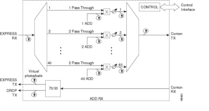
The double-slot 40-channel Wavelength Cross-Connect C Band (40-WXC-C) card selectively sends any wavelength combination coming from nine input ports to a common output port. The device can manage up to 41 channels spaced at 100GHz on each port according to the channel grid in Table 7-6. Each channel can be selected from any input. The card is optically passive and provides bidirectional capability. It can be installed in Slots 1 to 6 and 12 to 17.
.The 40-WXC-C card provides the following features:
•
•
•
•
The 40-WXC-C card acts as a selector element with the following characteristics:
•
•
•
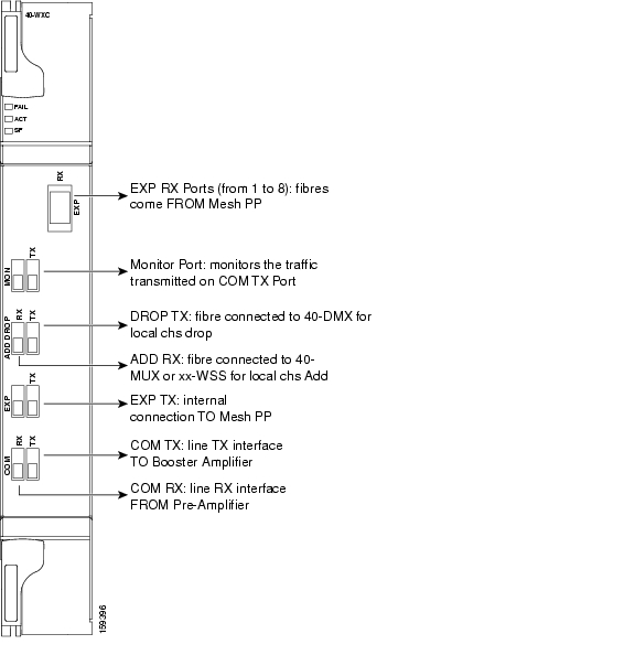
7.10.1 40-WXC-C Faceplate Ports
The 40-WXC-C card has six types of ports:
•
•
•
•
•
•
Figure 7-27 shows the 40-WXC-C card faceplate.
Figure 7-27 40-WXC-C Faceplate
7.10.2 40-WXC-C Block Diagram
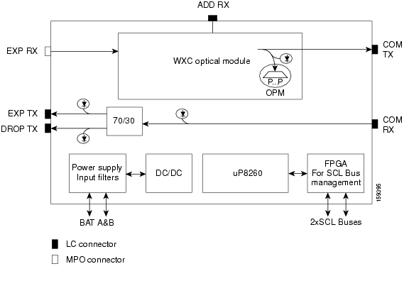
Figure 7-28 shows the 40-WXC-C optical module functional block diagram.
Figure 7-28 40-WXC-C Optical Module Functional Block Diagram
7.10.3 40-WXC-C Power Monitoring
The 40-WXC-C has 83 physical diodes (P1 through P40) that monitor power at the outputs of the card. Table 7-30 describes the physical diodes.
Table 7-30 40-WXC-C Physical Photodiode Port Calibration
P1
DROP
DROP TX
P2
EXP
EXP RX
PDi31
RX
Add i RX ports (that is, channel input Add i RX power), up to 40 ports and therefore 40 PDs 1
PDi4 1
TX
COM TX port (that is, per-channel output COM TX power) up to 40 channels and therefore 40 PDs
PD5
COM
COM TX port (that is, total output COM TX power)
1 i indicates any channel from 01 through 40.
Additionally, the 40-WXC-C has two virtual diodes. Virtual diodes are monitor points for each physical photodiode; they are identified with a physical diode relative to the way that the physical diode is identified with one of the two interlink (ILK) ports. Table 7-31 lists the virtual diodes.
7.10.4 40-WXC-C Channel Plan
Table 7-32 shows the 40 ITU-T 100-GHz-spaced, C band channels (wavelengths) that are cross connected by the 40-WXC-C card.
Table 7-32 40-WXC-C Channel Plan
Ch. 01
29.5
196
1529.55
B30.3
30.3
195.9
1530.33
31.1
195.8
1531.12
31.9
195.7
1531.90
32.6
195.6
1532.68
33.4
195.5
1533.47
B34.2
34.2
195.4
1534.25
35.0
195.3
1535.04
35.8
195.2
1535.82
36.6
195.1
1536.61
37.4
195
1537.40
B38.1
38.1
194.9
1538.19
38.9
194.8
1538.98
39.7
194.7
1539.77
40.5
194.6
1540.56
41.3
194.5
1541.35
B42.1
42.1
194.4
1542.14
42.9
194.3
1542.94
43.7
194.2
1543.73
44.5
194.1
1544.53
45.3
194
1545.32
B46.1
46.1
193.9
1546.12
46.9
193.8
1546.92
47.7
193.7
1547.72
48.5
193.6
1548.51
49.3
193.5
1549.32
B50.1
50.1
193.4
1550.12
50.9
193.3
1550.92
51.7
193.2
1551.72
52.5
193.1
1552.52
53.3
193
1553.33
B54.1
54.1
192.9
1554.13
54.9
192.8
1554.94
55.7
192.7
1555.75
56.5
192.6
1556.55
57.3
192.5
1557.36
B58.1
58.1
192.4
1558.17
58.9
192.3
1558.98
59.7
192.2
1559.79
60.6
192.1
1560.61
61.4
192
1561.42
1 This channel is unused by the 40-WXC-C
7.10.5 40-WXC-C Card-Level Indicators
The 40-WXC-C card has three card-level LED indicators described in Table 7-33.
7.10.6 40-WXC-C Port-Level Indicators
You can find the alarm status of the 40-WXC-C card ports using the LCD screen on the ONS 15454 fan-tray assembly. The screen displays the number and severity of alarms on a given port or slot. For the procedure to view these counts, refer to "Manage Alarms" in the Cisco ONS 15454 DWDM Procedure Guide.
7.11 MMU Card
The single-slot Mesh Multi-Ring Upgrade Module (MMU) card supports multiring and mesh upgrades for ROADM nodes in both the C band and the L band. Mesh/multiring upgrade is the capability to optically bypass a given wavelength from one section of the network or ring to another one without requiring 3R regeneration. In each node, you need to install one east MMU and one west MMU. The card can be installed in Slots 1 through 6 and 12 through 17.
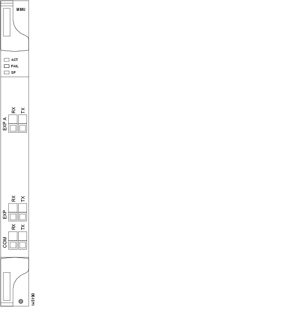
7.11.1 MMU Faceplate Ports
The MMU has six types of ports:
•
•
•
•
•
•
Figure 7-29 shows the MMU card faceplate.
Figure 7-29 MMU Faceplate and Ports
7.11.2 MMU Block Diagram
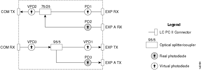
Figure 7-30 provides a high-level functional block diagram of the MMU card.
Figure 7-30 MMU Block Diagram
7.11.3 MMU Power Monitoring
Physical photodiodes P1 through P3 monitor the power for the MMU card. The returned power level values are calibrated to the ports as shown in Table 7-34. VP1 to VP3 are virtual photodiodes that have been created by adding (by software computation) the relevant path insertion losses of the optical splitters (stored in the module) to the real photodiode (P1 to P3) measurement.
7.11.4 MMU Card-Level Indicators
Table 7-35 describes the three card-level LED indicators on the MMU card.
7.11.5 MMU Port-Level Indicators
You can find the alarm status of the MMU card's ports using the LCD screen on the ONS 15454 fan-tray assembly. The screen displays the number and severity of alarms on a given port or slot. For the procedure to view these counts, refer to "Manage Alarms" in the Cisco ONS 15454 DWDM Procedure Guide.
![]()
![]()
![]()
![]()
![]()
![]()
![]()
![]()
Posted: Mon Oct 22 06:36:23 PDT 2007
All contents are Copyright © 1992--2007 Cisco Systems, Inc. All rights reserved.
Important Notices and Privacy Statement.