|
|

Table Of Contents
9.2.2 DCC/GCC/OSC Terminations
9.3 Configuring Mesh DWDM Networks
9.3.1 Line Termination Mesh Node
9.3.2 XC Termination Mesh Node
9.3.3 Mesh Patch Panels and Shelf Layouts
9.4.1 OSC Link Termination Fiber-Optic Cabling
9.4.2 Hub Node Fiber-Optic Cabling
9.4.3 Terminal Node Fiber-Optic Cabling
9.4.4 Line Amplifier Node Fiber-Optic Cabling
9.4.5 OSC Regeneration Node Fiber-Optic Cabling
9.4.6 Amplified or Passive OADM Node Fiber-Optic Cabling
9.4.7 ROADM Node Fiber-Optic Cabling
Node Reference
This chapter explains the ONS 15454 dense wavelength division multiplexing (DWDM) node types that are available for the ONS 15454. The DWDM node type is determined by the type of amplifier and filter cards that are installed in an ONS 15454. The chapter also explains the DWDM automatic power control (APC), reconfigurable optical add/drop multiplexing (ROADM) power equalization, span loss verification, and automatic node setup (ANS) functions.
Note
Unless otherwise specified, "ONS 15454" refers to both ANSI and ETSI shelf assemblies.
Note
Chapter topics include:
•
9.1 DWDM Node Configurations
The ONS 15454 supports the following DWDM node configurations: hub, terminal, optical add/drop multiplexing (OADM), reconfigurable OADM (ROADM), anti-amplified spontaneous emission (anti-ASE), line amplifier, optical service channel (OSC) regeneration line, multishelf nodes, and node configurations for mesh networks. All node configurations can be provisioned with C-band or L-band cards except the OADM and anti-ASE nodes. These nodes require AD-xB-xx.x or AD-xC-xx.x cards, which are C-band only. All node configurations can be single-shelf or multishelf.
Note
Note
9.1.1 Hub Node
A hub node is a single ONS 15454 node equipped with two TCC2/TCC2P cards and one of the following combinations:
•
•
•
•
Note
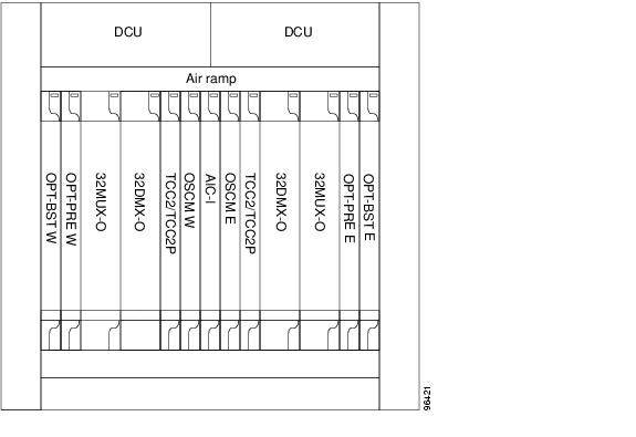
A dispersion compensation unit (DCU) can also be added, if necessary. The hub node does not support both DWDM and time-division multiplexing (TDM) applications because the DWDM slot requirements do not provide room for TDM cards. Figure 9-1 shows a hub node configuration with 32MUX-O and 32DMX-O cards installed.
Figure 9-1 Hub Node Configuration Example with 32-Channel C-Band Cards
Figure 9-2 shows a 40-channel hub node configuration with 40-WSS-C cards installed.
Figure 9-2 Hub Node Configuration Example with 40-WSS-C Cards
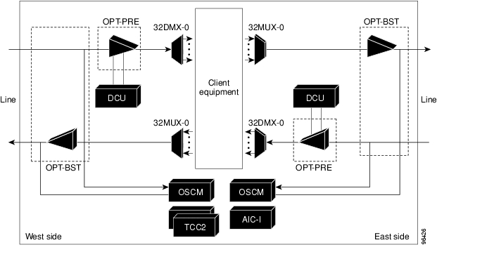
Figure 9-3 shows the channel flow for a hub node. Up to 32 channels from the client ports are multiplexed and equalized onto one fiber. Then, multiplexed channels are transmitted to the OPT-BST amplifier. The OPT-BST output is combined with an output signal from the OSCM card and transmitted to the other side.
Received signals are divided between the OSCM card and an OPT-PRE card. Dispersion compensation is applied to the signal received by the OPT-PRE amplifier, and it is then sent to the 32DMX-O card, which demultiplexes and attenuates the input signal.
Figure 9-3 Hub Node Channel Flow Example
9.1.2 Terminal Node
A terminal node is a single ONS 15454 node equipped with two TCC2/TCC2P cards and one of the following combinations:
•
•
•
•
•
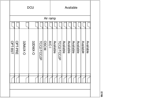
Terminal nodes can be installed in Slots 1 through 6 or Slots 12 through 17. The side where cards are installed is always assigned as Side A. Figure 9-4 shows an example of a terminal configuration with a 2MUX-O card installed. The channel flow for a terminal node is the same as the hub node ( Figure 9-3).
Figure 9-4 Terminal Node Configuration With 32MUX-O Cards Installed
Figure 9-5 shows an example of a terminal configuration with a 40-WSS-C card installed.
Figure 9-5 Terminal Node Configuration with 40-WSS-C Cards Installed
Figure 9-5 shows an example of a terminal configuration with a 40-MUX-C card installed.
Figure 9-6 Terminal Node with 40-MUX-C Cards Installed
9.1.3 OADM Node
An OADM node is a single ONS 15454 node equipped with cards installed on both sides and at least one AD-xC-xx.x card or one AD-xB-xx.x card and two TCC2/TCC2P cards. 32MUX-O/40-MUX-C or 32DMX-O/40-DMX-C cards cannot be installed in an OADM node. In an OADM node, channels can be added or dropped independently from each direction and then passed through the reflected bands of all OADMs in the DWDM node (called express path). They can also be passed through one OADM card to another OADM card without using a TDM ITU-T line card (called optical pass-through) if an external patchcord is installed.
Unlike express path, an optical pass-through channel can be converted later to an add/drop channel in an altered ring without affecting another channel. OADM amplifier placement and required card placement is determined by the Cisco MetroPlanner tool or your site plan.
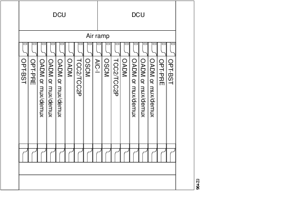
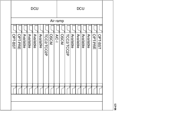
OADM nodes can be amplified or passive. In amplified OADMs, booster and preamplifier cards are installed on bode sides of the node. Figure 9-7 shows an example of an amplified OADM node configuration. In addition, OADM nodes can be asymmetric. Amplifiers may be installed in one side, but not the other. Or preamplifiers may be installed in one side, and a booster in the other.
Figure 9-7 Amplified OADM Node Configuration Example
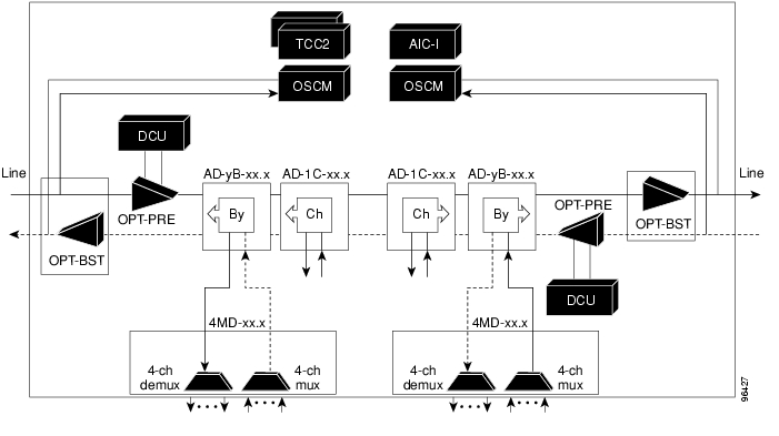
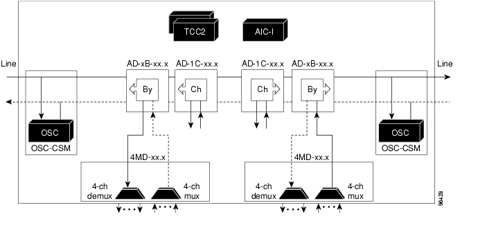
Figure 9-8 shows an example of the channel flow on the amplified OADM node. Since the 32-wavelength plan is based on eight bands (each band contains four channels), optical adding and dropping can be performed at the band level and/or at the channel level (meaning individual channels can be dropped).
Figure 9-8 Amplified OADM Node Channel Flow Example
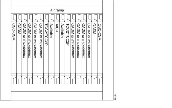
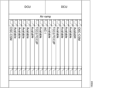
Figure 9-9 shows an example of a passive OADM node configuration. The passive OADM node is equipped with a band filter, one four-channel multiplexer/demultiplexer, and a channel filter on each side of the node.
Figure 9-9 Passive OADM Node Configuration Example
Figure 9-10 shows an example of traffic flow on the passive OADM node. The signal flow of the channels is the same as the amplified OADM, except that the OSC-CSM card is used instead of the OPT-BST and OSCM cards.
Figure 9-10 Passive OADM Node Channel Flow Example
9.1.4 ROADM Node
A ROADM node adds and drops wavelengths without changing the physical fiber connections. A ROADM node is equipped with two TCC2/TCC2P cards and one of the following combinations:
•
•
•
Transponders (TXPs) and muxponders (MXPs) can be installed in Slots 6 and 12 and, if amplification is not used, in any open slot.
Note
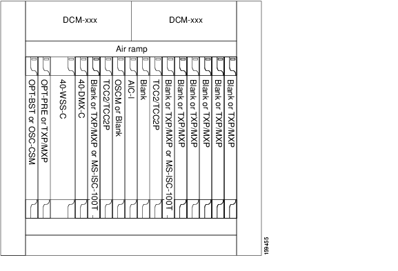
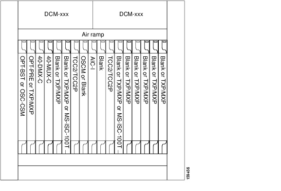
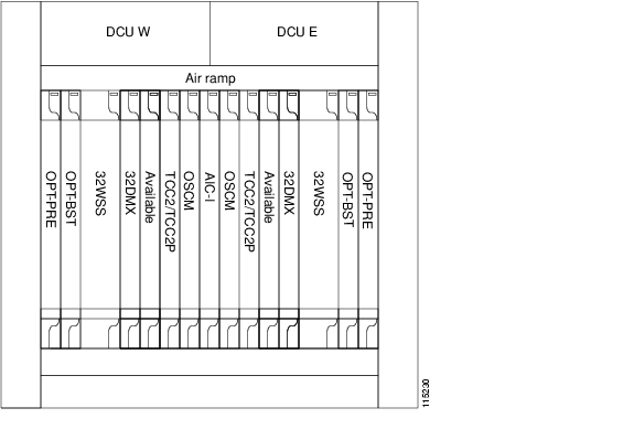
Figure 9-11 shows an example of an amplified ROADM node configuration with 32DMX cards installed.
Figure 9-11 ROADM Node with 32DMX Cards Installed
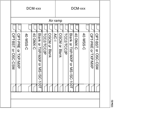
Figure 9-12 shows an example of an amplified ROADM node configuration with 40-WSS-C cards installed.
Figure 9-12 ROADM Node with 40-WSS-C Cards Installed
Figure 9-13 shows an example of an ROADM node with 32WSS-L and 32DMX-L cards installed.
Figure 9-13 ROADM Node with 32WSS-L and 32DMX-L Cards Installed
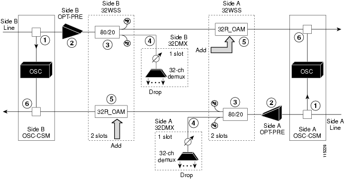
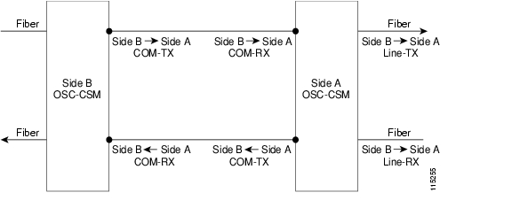
Figure 9-14 shows an example of an ROADM optical signal flow from Side A to Side B. The optical signal flow from Side B to Side A follows an identical path through the Side B OSC-CSM and 32WSS or 40-WSS-C cards. In this example, OSC-CSM cards are installed so OPT-BSTs are not needed.
Figure 9-14 ROADM Optical Signal Flow Example
9.1.5 Anti-ASE Node
In a mesh ring network, the ONS 15454 requires a node configuration that prevents ASE accumulation and lasing. An anti-ASE node can be created by configuring a hub node or an OADM node with some modifications. No channels can travel through the express path, but they can be demultiplexed and dropped at the channel level on one side and added and multiplexed on the other side.
The hub node is the preferred node configuration when some channels are connected in pass-through mode. For rings that require a limited number of channels, combine AD-xB-xx.x and 4MD-xx.x cards, or cascade AD-xC-xx.x cards. See Figure 9-8.
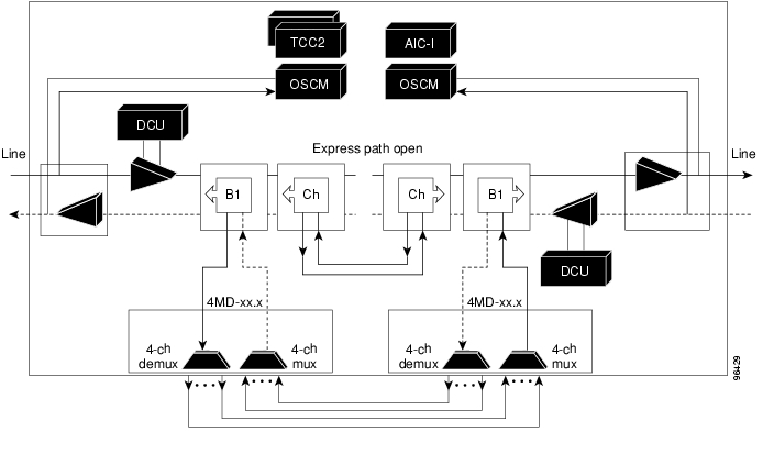
Figure 9-15 shows an anti-ASE node that uses all wavelengths in the pass-through mode. Use Cisco MetroPlanner to determine the best configuration for anti-ASE nodes.
Figure 9-15 Anti-ASE Node Channel Flow Example
9.1.6 Line Amplifier Node
A line amplifier node is a single ONS 15454 node that is used to amplify the optical signal in long spans. The line amplifier node can be equipped with one of the following sets of cards:
•
•
•
Attenuators might also be required between each preamplifier and OPT-BST amplifier to match the optical input power value and to maintain the amplifier gain tilt value.
Two OSCM cards are connected to the OPT-BST cards to multiplex the OSC signal with the pass-though channels. If the node does not contain an OPT-BST card, OSC-CSM cards must be installed instead of OSCM cards. Figure 9-16 shows an example of a line amplifier node configuration using OPT-BST, OPT-PRE, and OSCM cards.
Figure 9-16 Line Amplifier Node Configuration Example
9.1.7 OSC Regeneration Node
The OSC regeneration node is added to the DWDM networks for two purposes:
•
•
OSC regeneration nodes require two OSC-CSM cards, as shown in Figure 9-17. The cards are installed in each side of the shelf.
Figure 9-17 OSC Regeneration Line Node Configuration Example
Figure 9-18 shows the OSC regeneration line node signal flow.
Figure 9-18 OSC Regeneration Line Node Flow
9.2 Multishelf Node
An ONS 15454 node provisioned as a multishelf node can manage up to eight subtending shelves as a single entity. The node controller is the main shelf; its TCC2/TCC2P cards run multishelf functions. Each subtending shelf must be equipped with TCC2/TCC2P cards, which run the shelf functions. For internal data exchange between the node controller shelf and subtending shelves, the node controller shelf must be equipped with redundant MS-ISC-100T cards or, as an alternative, the Catalyst 2950 switch. Cisco recommends using the MS-ISC-100T cards. If using the Catalyst 2950, it is installed on one of multishelf racks. All subtending shelves must be located in the same site at a maximum distance of 100 meters or 328 feet from the Ethernet switches used to support the communication LAN. Figure 9-19 shows an example of a multishelf node configuration.
Figure 9-19 Multishelf Node Configuration
A multishelf node has a single public IP address for all client interfaces (Cisco Transport Controller [CTC], Transaction Language One [TL1], Simple Network Management Protocol [SNMP], and HTTP); a client can only connect to the node controller shelf, not to the subtending shelves. The user interface and subtending shelves are connected to a patch panel using straight-through (CAT-5) LAN cables.
The node controller shelf has the following functions:
•
•
The subtending shelves have the following functions:
•
•
9.2.1 Multishelf Node Layout
Multishelf configurations are configured by Cisco MetroPlanner and are automatically discovered by the CTC software. In a typical multishelf installation, all optical units are equipped on the node controller shelf and TXP/MXP cards are equipped in the aggregated subtended shelves. In addition, all empty slots in the node controller shelf can be equipped with TXP/MXP cards. In a DWDM mesh network, up to eight optical sides can be configured with client and optical cards installed in different shelves to support mesh and ring-protected signal output.
9.2.2 DCC/GCC/OSC Terminations
A multishelf node provides the same communication channels as a single-shelf node:
•
•
The maximum number of DCC/GCC/OSC terminations that are supported in a multishelf node is 48.
9.3 Configuring Mesh DWDM Networks
ONS 15454 shelves can be configured in mesh DWDM networks using the 40-WXC-C wavelength cross-connect cards, multishelf provisioning, and the 40-channel patch panel, four-degree patch panel, and eight-degree patch panels. ONS 15454 DWDM mesh configurations can be up to four degrees (four optical directions) when the four-degree patch panel patch panel is installed, and up to eight degrees (eight optical directions) when the eight-degree patch panel is installed. Two mesh node types are available, the line termination mesh node and the cross-connect (XC) termination mesh node.
9.3.1 Line Termination Mesh Node
The line termination mesh node is installed in native Software Release 8.0 mesh networks. Line termination mesh nodes can support between one and eight line terminations. Each line direction requires the following cards: 40-WXC-C, 40-MUX-C, 40-DMX-C, a preamplifier and a booster. Within this configuration, the following substitutions can be used:
•
•
•
Each side of the line termination mesh node is connected as follows:
•
•
•
•
•
•
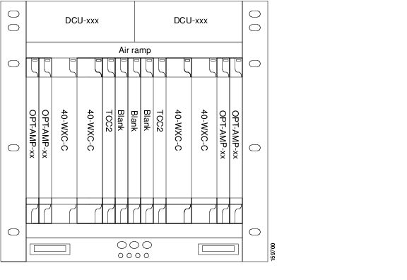
Figure 9-20 shows one shelf from a line termination node. (Examples of line termination nodes in four-degree and eight-degree mesh networks are shown in Figure 9-27 and Figure 9-28.)
Figure 9-20 Line Termination Mesh Node Shelf
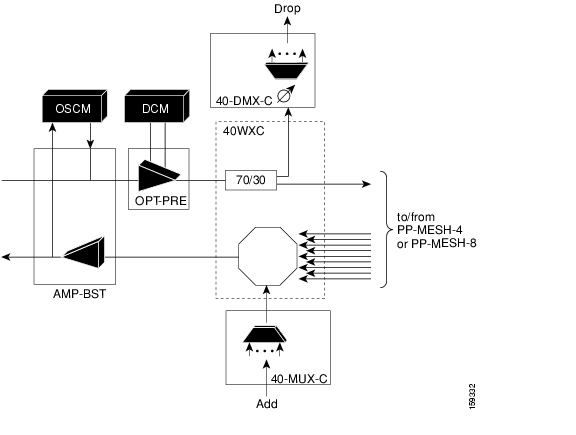
Figure 9-21 shows a functional block diagram of one line termination side using 40-WXC-C and 40-MUX-C cards.
Figure 9-21 Line Termination Mesh Node Side—40-MUX-C Cards
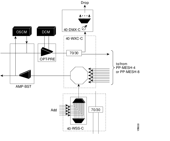
Figure 9-22 shows a functional block diagram line termination side using 40-WXC-C and 40-WSS-C cards.
Figure 9-22 Line Termination Mesh Node Side—40-WSS-C Cards
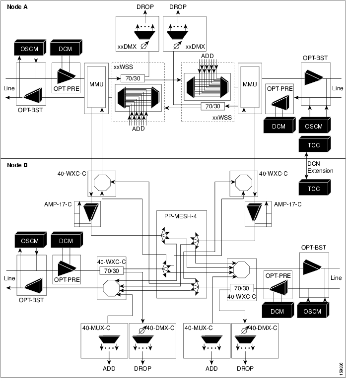
Figure 9-23 shows a functional block diagram of a node that interconnects a ROADM with MMU cards with two native line termination mesh sides.
Figure 9-23 Line Termination Mesh Nodes—ROADM With MMU Cards
9.3.2 XC Termination Mesh Node
The XC termination mesh node, shown in Figure 9-24, is the second mesh node type. It is used to upgrade a non-mesh node to a mesh node or to interconnect two non-mesh nodes. The XC termination mesh nodes contain the following cards:
•
•
The XC termination mesh node is connected as follows:
•
•
•
•
•
•
Figure 9-24 XC Termination Mesh Node Shelf
9.3.3 Mesh Patch Panels and Shelf Layouts
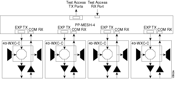
ONS 15454 mesh topologies require the installation of a four-degree patch panel (PP-MESH-4) or eight-degree patch panel (PP-MESH-8). If the four-degree patch panel is installed, mesh topologies of up to four degrees can be created. If the eight-degree patch panel patch panel is installed, mesh topologies of up to eight degrees can be created. The four-degree patch panel contains four 1x4 optical splitters, and the eight-degree patch panel contains eight 1x8 splitters. Each mesh patch panel contains a 2x8 splitter that is used for the test access transmit and receive ports. Figure 9-25 shows a block diagram for the four-degree patch panel.
Figure 9-25 Four-Degree Patch Panel Block Diagram
At the mesh patch panel, the signal is split into four signals (if four-degree patch panel is used) or eight signals (if an eight-degree patch panel is used). Figure 9-26 shows the signal flow at the four-degree patch panel. 40-WXC-C cards connect to the four-degree patch panel at the EXP TX and COM RX ports.
Figure 9-26 Four-Degree Patch Panel Signal Flow
The mesh patch panels interconnect 40-WXC-C cards to create mesh networks, including four-degree and eight-degree mesh topologies. In addition, shelves with 40-WXC-C cards can be configured with mesh patch panels to create multiring, MMU-based mesh nodes. 40-WXC-C cards can be installed in ROADM nodes with MMU cards to upgrade a two-degree MMU-based ROADM node into four-degree or eight-degree mesh nodes. Figure 9-27 shows the ROADM node with MMU cards configuration after it has been upgraded into a four-degree mesh topology.
Figure 9-27 Layout for ROADM Node with MMU Cards and Four-Degree Mesh Topology
The following figures show different mesh configurations at the shelf level. Figure 9-28 shows a basic four-degree mesh node layout based on the shelf configuration shown in Figure 9-20.
Figure 9-28 Four-Degree Line Termination Mesh Node Layout
Figure 9-29 shows a protected four-degree mesh node layout based on the shelf configuration shown in Figure 9-20.
Figure 9-29 Four-Degree Protected Line Termination Mesh Node Layout
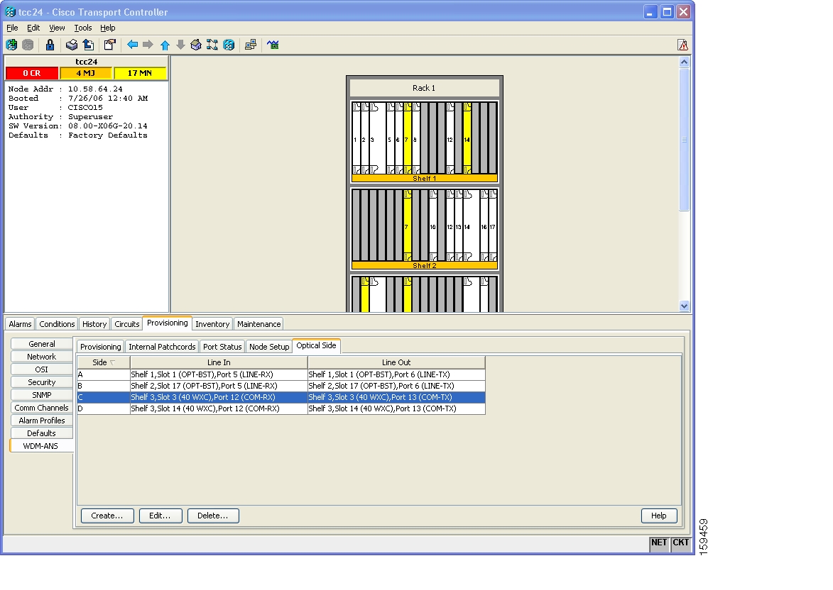
9.3.4 Optical Sides
When 40-WXC-C cards are installed, DWDM nodes configured in multishelf mode can be connected to up to eight different spans. The sides are identified by the letters, A, B, C, D, E, F, G, and H. Sides are viewed and managed from the Provisioning > WDM-ANS > Optical Sides tab, shown in Figure 9-30. Each side identifies a span to which the node is connected.
Note
Figure 9-30 Optical Side Tab
Sides can be divided into three stages.
•
•
•
Figure 9-31 shows a conceptual view of the interconnecting sides. Up to eight sides are supported, and each side contains the TXP/MXP, fiber, and the A/D stages.
Figure 9-31 Interconnecting Sides Conceptual View
Fiber stage cards include:
•
•
•
Table 9-1 shows the fiber stage layouts supported by DWDM mesh nodes. In the table, OPT-BST includes the OPT-BST, OPT-BST-E, and OPT-BST-L cards. OPT-AMP includes the OPT-AMP-L and OPT-AMP-17-C cards configured in either OPT-PRE or OPT-LINE mode.
Note
The A/D stage is divided into three node types:
•
•
•
Stages are built by active cards and patchcords. However, the interconnecting sides are completed by the mesh patch panels (four-degree patch panel or eight-degree patch panel), or by patchcords connected to EXP-RX/EXP-TX ports in legacy nodes.
All DWDM cards installed in an ONS 15454 belong to a side. A side can be identified by a letter (A, B, C, D, E, F, G, or H), or by the ports that are physically connected to the spans. These ports are called "side line ports." Side line ports can be:
•
•
–
–
–
–
•
–
–
–
ONS 15454 Slots 1 through 6 and Slots 12 through 17 can each receive a Side ID if a 40-WXC-C card is installed in each group.
•
•
•
Side IDs are assigned automatically. You can create a side manually using CTC or TL1 if the following conditions are met:
•
•
•
If the ONS 15454 software finds a user-defined side, it uses the user-assigned label for the side and assigns the next Side ID user label +1. A side is marked "Unknown" if the next side label after user-assigned Side ID exceeds the number allowed (for example, E in a four-degree mesh node). Every optical card installed in a node is associated to the Side ID assigned to the slot in which the card is installed.
A side value is never applied to shelves where TXP, MXP, ADM-10G, GE_XP or 20GE_XP cards are installed because these cards are not involved in the automatic patchcord creation. If you delete a Side ID, the Side ID value for all cards associated to the side is changed to "Unknown."
Note
The following tables show sample ONS 15454 configurations using the sides. Table 9-2 shows a standard ROADM shelf with Sides A and B provisioned. The shelf is connected to seven shelves containing TXP, MXP, ADM-10G, GE_XP, or 10GE_XP cards.
Table 9-3 shows a protected ROADM shelf. In this example, Side A and B are Slots 1 through 6 in Shelves 1 and 2. 40-WSS-C/40-DMX-C cards are installed in Sides A and B. Slots 12 through 17 in Shelves 1 and 2 contain TXP, MXP, ADM-10G, GE_XP, or 10GE_XP cards.
Table 9-4 shows a four-degree mesh node. Side A is Shelf 1, Slots 1 through 6. Side B and C are Shelf 2, Slots 1 through 6 and 12 through 17, and Side D is Shelf 3, Slots 1 through 6. 40-WXC-C cards in line termination mode are installed in Sides A through D.
Table 9-5 shows a protected four-degree mesh node example. In the example, Sides A through D are assigned to Slots 1 through 6 in Shelves 1 through 4.
Table 9-6 shows a protected four-degree mesh node example. In the example, Sides A through D are assigned to Slots 1 through 4 in Shelves 1 through 4, and TXP, MXP, ADM-10G, GE_XP or 10GE_XP cards are installed in Shelves 1 through 4, Slots 12-17, and Shelves 5 through 8, Slots 1 through 6 and 12 through 17.
Table 9-7 shows a four-degree mesh node provisioned as an upgrade. In the example, Sides A through D are assigned to Slots 1 through 4. and 12 through 17 in Shelves 1and 2. 40-WXC-C cards in XC termination mode are installed in Sides A and B, and 40-WXC-C cards in line termination mode are installed in Sides C and D.
Table 9-8 shows an eight-degree mesh node. In the example, Sides A through H are assigned to Slots 1 through 6 in Shelf 1, Slots 1 through 6 and 12 through 17 in Shelves 2 through 4, and Slots 1 through 6 in Shelf 5. 40-WXC-C cards in line termination mode are installed in Sides A through H.
Table 9-9 shows another eight-degree mesh node. In the example, Sides A through H are assigned to Slots 1 through 6 in all shelves (Shelves 1 through 8). 40-WXC-C cards in line termination mode are installed in Sides A through H.
Table 9-10 shows a four-degree mesh node with a user-defined side. Because the software assigns sides consecutively, and because the mesh node is four-degrees, the side assigned to Shelf 5, Slots 1 through 6 is "Unknown."
Table 9-10 Multishelf Four-Degree Mesh Node User-Defined Layout Example
1
WXC Line Termination
A
TXP/MXP
—
2
TXP/MXP
—
WXC Line Termination
C1
3
WXC Line Termination
D
TXP/MXP
—
4
TXP/MXP
—
TXP/MXP
—
5
WXC Line Termination
U2
TXP/MXP
—
6
TXP/MXP
—
TXP/MXP
—
7
TXP/MXP
—
TXP/MXP
—
8
TXP/MXP
—
TXP/MXP
—
1 User-defined
2 Unknown
9.4 DWDM Node Cabling
DWDM node cabling is specified by the Cisco MetroPlanner Internal Connections table. The following sections provide examples of the cabling that you will typically install for common DWDM node types.
Note
9.4.1 OSC Link Termination Fiber-Optic Cabling
OSC link termination cabling include the following characteristics:
•
•
•
•
•
•
•
•
Figure 9-32 shows an example of OSC fibering for a hub node with OSCM cards installed.
Figure 9-32 Fibering OSC Terminations—Hub Node with OSCM Cards
9.4.2 Hub Node Fiber-Optic Cabling
The following rules generally apply to hub node cabling:
•
•
•
•
•
•
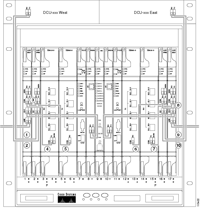
Figure 9-33 shows an example of a hub node with cabling. In the example, OSCM cards are installed. If OSC-CSM cards are installed, they are usually installed in Slots 1 and 17.
Figure 9-33 Fibering a Hub Node
Side A DCU TX to Side A OPT-PRE DC RX1
Side B 32DMX-O COM RX to Side B OPT-PRE COM TX
Side A DCU RX to Side A OPT-PRE DC TX1
Side B 32MUX-O COM TX to Side B OPT-BST COM RX
Side A OPT-BST COM TX to Side A OPT-PRE COM RX
Side B OPT-PRE COM RX to Side B OPT-BST COM TX
Side A OPT-BST COM RX to Side A 32MUX-O COM TX
Side B DCU TX to Side B OPT-PRE DC RX1
Side A OPT-PRE COM TX to Side A 32DMX-O COM RX
Side B DCU RX to Side B OPT-PRE DC TX1
1 If a DCU is not installed, a 4-dB attenuator loop, +/- 1 dB must be installed between the OPT-PRE DC ports.
9.4.3 Terminal Node Fiber-Optic Cabling
The following rules generally apply to terminal node cabling:
•
•
•
•
9.4.4 Line Amplifier Node Fiber-Optic Cabling
The following rules generally apply to line amplifier node cabling:
•
–
–
–
–
•
–
–
•
•
–
–
•
Figure 9-34 shows an example of a line amplifier node with cabling.
Figure 9-34 Fibering a Line Amplifier Node
Side A DCU TX to Side A OPT-PRE DC RX1
Side A OPT-BST COM RX to Side B OPT-PRE COM TX
Side A DCU RX to Side A OPT-PRE DC TX1
Side A OPT-BST COM RX to Side B OPT-PRE COM TX
Side A OPT-BST COM TX to Side A OPT-PRE COM RX
Side B DCU TX to Side B OPT-PRE DC RX1
Side A OPT-PRE COM TX to Side B OPT-BST COM RX
Side B DCU RX to Side B OPT-PRE DC TX1
1 If a DCU is not installed, a 4-dB attenuator loop, +/- 1 dB, must be installed between the OPT-PRE DC ports.
9.4.5 OSC Regeneration Node Fiber-Optic Cabling
The following rules generally apply to OSC regeneration node cabling:
•
•
•
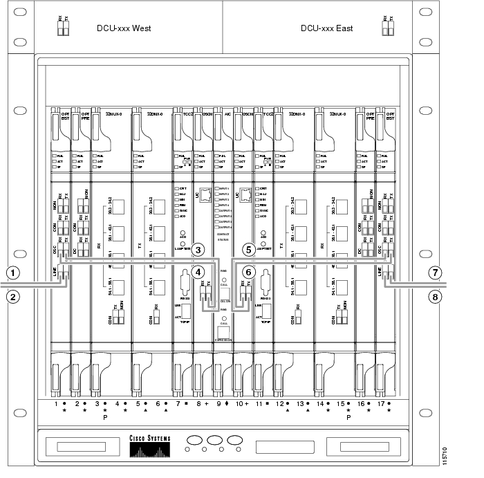
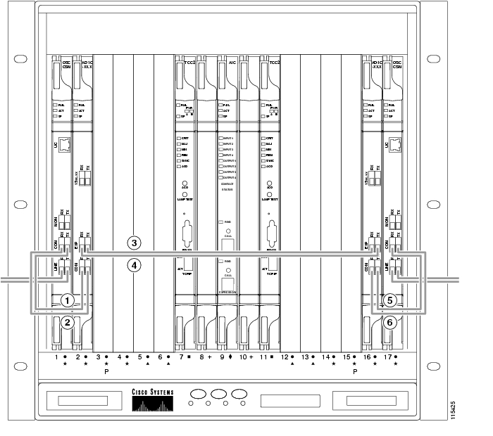
Figure 9-35 shows an example of an OSC regeneration node with cabling.
Figure 9-35 Fibering an OSC Regeneration Node
9.4.6 Amplified or Passive OADM Node Fiber-Optic Cabling
The two sides of the OADM node do not need to be symmetrical. On each side, Cisco MetroPlanner can create one of the following four configurations:
•
•
•
•
Note
The following rules generally apply for OADM node express path cabled connections:
•
•
•
•
•
•
•
•
•
•
•
•
•
The following rules generally apply for OADM node add/drop path cabled connections:
•
–
–
•
•
•
The following rules generally apply for OADM node pass-through path cabled connections:
•
•
•
•
•
•
•
•
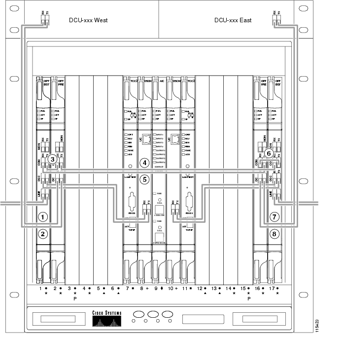
Figure 9-36 shows an example of an amplified OADM node with AD-1C-xx.x cards installed.
Note
Figure 9-36 Fibering an Amplified OADM Node
Side A DCU TX to Side A OPT-PRE DC RX1
Side A AD-1C-xx.x EXP RX to Side B AD-1C-xx.x EXP TX
Side A DCU RX to Side A OPT-PRE DC TX1
Side B TXP_MR_2.5G DWDM RX to Side B AD-1C-xx.x (15xx.xx) TX
Side A OPT-BST COM TX to Side A OPT-PRE COM RX
Side B TXP_MR_2.5G DWDM TX to Side B AD-1C-xx.x (15xx.xx) RX
Side A OPT-BST COM RX to Side A AD-1C-xx.x COM TX
Side B AD-1C-xx.x COM RX to OPT-PRE COM TX
Side A OPT-PRE COM TX to Side A AD-1C-xx.x COM RX
Side B AD-1C-xx.x COM TX to OPT-BST COM RX
Side A AD-1C-xx.x (15xx.xx) RX to Side A TXP_MR_2.5G DWDM TX
Side B OPT-PRE COM RX to Side B OPT-BST COM TX
Side A AD-1C-xx.x (15xx.xx) TX to Side A TXP_MR_2.5G DWDM RX
Side B DCU TX to Side B OPT-PRE DC RX1
Side A AD-1C-xx.x EXP TX to Side B AD-1C-xx.x EXP RX
Side B DCU RX to Side B OPT-PRE DC TX1
1 If a DCU is not installed, a 4-dB attenuator loop, +/ 1 dB, must be installed between the OPT-PRE DC ports.
Figure 9-37 shows an example of a passive OADM node with two AD-1C-xx.x cards installed.
Figure 9-37 Fibering a Passive OADM Node
9.4.7 ROADM Node Fiber-Optic Cabling
The following rules generally apply to ROADM node cabling:
•
•
•
•
•
•
•
•
•
•
•
•
•
•
•
•
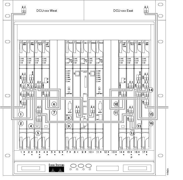
Figure 9-38 shows an example of an amplified ROADM node with cabling.
Note
Figure 9-38 Fibering a ROADM Node
Side A DCU TX to Side A OPT-PRE DC RX1
Side A 32WSS EXP RX to Side B 32WSS EXP TX
Side A DCU RX to Side A OPT-PRE DC TX1
Side B 32DMX COM RX to Side B 32WSS DROP TX
Side A OPT-BST COM TX to Side A OPT-PRE COM RX
Side B 32WSS COM RX to Side B OPT-PRE COM TX
Side A 32WSS COM TX to Side A OPT-BST COM RX
Side B 32WSS COM TX to Side B OPT-BST COM RX
Side A 32WSS COM RX to Side A OPT-PRE COM TX
Side B OPT-BST COM TX to Side B OPT-PRE COM RX
Side A 32DMX COM RX to Side A 32WSS DROP TX
Side B DCU RX to Side B OPT-PRE DC TX1
Side A 32WSS EXP TX to Side B 32WSS EXP RX
Side B DCU TX to Side B OPT-PRE DC RX1
1 If a DCU is not installed, a 4-dB attenuator loop, +/-1 dB must be installed between the OPT-PRE DC ports.
9.5 Automatic Node Setup
Automatic node setup (ANS) is a TCC2/TCC2P function that adjusts values of the variable optical attenuators (VOAs) on the DWDM channel paths to equalize the per-channel power at the amplifier input. This power equalization means that at launch, all channels have the same amplifier power, independent from the input signal on the client interface and independent from the path crossed by the signal inside the node. This equalization is needed for two reasons:
•
•
To support ANS, integrated VOAs and photodiodes are provided in the following cards:
•
•
•
•
•
•
•
•
Optical power is equalized by regulating the VOAs. Based on the expected per-channel power, ANS automatically calculates the VOA values by:
•
•
VOAs operate in one of three working modes:
•
•
•
ANS calculates the following VOA provisioning parameters:
•
•
To allow you to modify ANS values based on your DWDM network requirements, provisioning parameters are divided into two contributions:
•
•
To complete the equalization, ANS requires the following information:
•
•
•
ANS assumes that every DWDM port is associated to one on the node side. The port-to-side association is based on node layout deriving from provisioned (or automatically calculated) internal patchcords. From CTC or TL1 you can:
•
•
•
•
•
After you launch ANS, one of the following statuses is provided for each ANS parameter:
•
•
•
•
•
•
Optical patchcords are passive devices that are modeled by the two termination points, each with an assigned slot and port. If user-provisioned optical patchcords exist, ANS checks that the new connection is feasible (according to internal connection rules) and returns a denied message if the user connection violates one of the rules. ANS requires the expected wavelength to be provisioned. When provisioning the expected wavelength, the following rules apply:
•
•
•
•
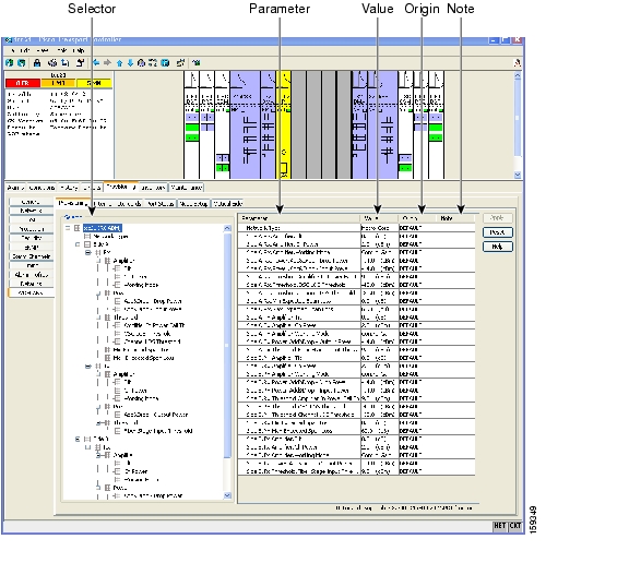
ONS 15454 ANS parameters set the values required for the node to operate successfully. Cisco MetroPlanner calculates the ANS parameters based on the requirements for a planned network. Cisco MetroPlanner exports the parameters to an ASCII, NE Update file. The NE Update file can then be imported by CTC to automatically provision the node for the network. All ANS parameters can be viewed and manually modified from the node view Provisioning > WDM-ANS > Provisioning tab, shown in Figure 9-39.
Figure 9-39 WDM-ANS Provisioning
The Provisioning > WDM-ANS > Provisioning tab presents the following information:
•
•
•
•
–
–
–
•
Table 9-11 shows the following information displayed for ANS parameters on the Provisioning > WDM-ANS > Provisioning tab.
•
•
•
•
•
•
•
Table 9-11 Provisioning > ANS-WDM > Provisioning Tab Parameters
i1
—
Network Type
Network Type
—
—
MC
U, T, FC, O, H, L, R
Rx
Amplifier
Side i.Rx.Amplifier.Tilt
0
30
0
T, FC, O, H, L, R
Side i.Rx.Amplifier.Gain
0
30
0
T, FC, O, H, L, R
Side i.Rx.Amplifier.Ch Power
-10
17
2
T, FC, O, H, L, R
Side i.Rx.Amplifier.Working Mode
—
—
CG
T, FC, O, H, L, R
—
Side i.Rx.Max Expected Span Loss
0
60
60
T, FC, O, H, L, R
Side i.Rx.Min Expected Span Loss
0
60
60
T, FC, O, H, L, R
Power
Side i Rx.Power.Far End
-50
30
U
T, FC, O, H, L, R
Side i Rx.Power.Add&Drop - Input Power
-50
30
14
T, FC, O, H, R
Side i.Rx.Power.Add&Drop - Drop Power
-50
30
14
T, FC, O, H, R
Side i.Rx.Power.Band n.Drop Power (where n = 1-8)
-50
30
14
FC, O
Side i.Rx.Power.Channel n.Drop Power Side B (where n = 1-322 or 1-403 )
-50
30
14
T, H, R
Thresholds
Side i.Rx.Threshold.OSC LOS Threshold
-50
30
U
T, FC, O, H, L, R
Side i.Rx.Threshold.Channel LOS Threshold
-50
30
U
T, FC, O, H, L, R
Side i Rx Amplifier In Power Fail Th
-50
30
Tx
Amplifier
Side i.Tx.Amplifier.Tilt
0
30
0
T, FC, O, H, L, R
Side i.Tx.Amplifier.Gain
0
30
0
T, FC, O, H, L, R
Side i.Tx.Amplifier.Ch Power
-10
17
2
T, FC, O, H, L, R
Side i.Tx.Amplifier.Working Mode
—
—
CG
T, FC, O, H, L, R
Power
Side i.Tx.Power.Add&Drop - Output Power
-50
30
14
T, FC, O, H, R
Side i.Tx.Power.Add&Drop - By-Pass Power
-50
30
14
H
Threshold
Side i.Tx.Threshold.Fiber Stage Input Threshold
-50
30
U
1 Where i = A, B, C, D, E, F, G, H
2 If 32-channel cards are installed
3 If 40-channel cards are installed
![]()
![]()
![]()
![]()
![]()
![]()
![]()
![]()
Posted: Mon Oct 22 05:47:36 PDT 2007
All contents are Copyright © 1992--2007 Cisco Systems, Inc. All rights reserved.
Important Notices and Privacy Statement.