|
|

Table Of Contents
Using the Cisco Transport Controller
3.3 Preparing Solaris Workstations to Run CTC
3.4 Connecting PCs to the ONS 15454
3.4.2 Local Area Network Connections
3.4.3 Remote Access to the ONS 15454
3.4.4 Connecting to the ONS 15454 with TL1 Terminals
3.5 Logging into the ONS 15454
3.9.1 Controlling Alarm Display
3.9.3 Setting Up General Node Information
3.9.4 Setting Up ONS 15454 Network Information
3.9.5 Setting Up ONS 15454 Security
3.9.6 Creating Protection Groups
3.9.7 Setting Up ONS 15454 Timing
3.10 Viewing ONS 15454 Inventory
3.11 Printing and Exporting CTC Data
3.12 Displaying CTC Data in Other Applications
3
Using the Cisco Transport Controller
This chapter explains how to connect computers to the Cisco ONS 15454 and set up the ONS 15454 using the Cisco Transport Controller (CTC) software.
3.1 Overview
CTC is a Java application that is downloaded from the Timing Communications and Control (TCC) card to your computer when you connect to the ONS 15454. CTC allows you to provision and manage the ONS 15454 using Netscape Navigator or Microsoft° Internet Explorer. You can also use TL1 commands to communicate with the ONS 15454 through VT100 terminals, VT100 emulation software, or you can Telnet to the node using TL1 port 2361.
To use CTC, your computer needs a web browser and appropriate versions of the Java Runtime Environment (JRE) and Java plug-ins. Netscape Communicator and required Java files are provided on the Cisco ONS 15454 software CD. You can install Netscape and the Java files using procedures in the following sections.
Each time you connect to an ONS 15454, a CTC launcher is downloaded from the ONS 15454 TCC card to your computer. The launcher verifies that the computer has a CTC version that matches the version on the TCC. If the computer does not have CTC, or if the version on the TCC is a later release, the launcher downloads the CTC application to the temporary directory designated by your computer's operating system. (For a detailed description of the TCC card, see the "Timing Communication and Control (TCC/TCC+) Card" section on page 2-7.)
3.2 Preparing PCs to Run CTC
The following minimum requirements are needed to run CTC from personal computers:
•
486 processor
•
•
•
•
•
•
•
Netscape Communicator is included on the Cisco ONS 15454 software CD. Internet Explorer 5.0 is included with Windows 98 second edition.
•
•
Note
Procedure: Install Netscape Communicator (Windows)
If a web browser is not installed, install Netscape Communicator or Microsoft Internet Explorer using procedures provided by those vendors. Netscape Communicator is provided on the Cisco ONS 15454 software CD. To install it:
Step 1
Step 2
Procedure: Install the Java Files (Windows)
Step 1
Step 2
Step 3
A message displays on the DOS screen stating the installation was successful.
Step 4
(a)
(b)
(c)
(d)
3.3 Preparing Solaris Workstations to Run CTC
To install CTC Release 2.2.0 software on Solaris workstations, the workstation must have Solaris 2.6 or 2.7 installed, with a minimum 128 megabytes of RAM. Use the following procedures to install Netscape and the appropriate Java files on the Solaris workstation.
Note
Procedure: Install qzip
To install Netscape, you need qzip. If q zip is not installed:
Step 1
Step 2
cd /var/tmptar xvf /CD/solaris/files.tarStep 3
mkdir -p /usr/local/bincp /var/tmp/Solaris/Netscape/qzip /usr/local/binStep 4
csh: % set path = ( /usr/local/bin /opt/NSCPcom $path )sh or ksh: # PATH=/usr/local/bin:/opt/NSCPcom:$PATH# export PATHStep 5
Procedure: Install Netscape Navigator (Solaris)
If Netscape Navigator 4.08 or Netscape Communicator 4.61 or later is not installed on the workstation, install it from the CTC Release 2.2.0 CD:
Step 1
Step 2
cd /var/tmptar xvf /CD/solaris/files.tarStep 3
tar xvf navigator-v408-export.sparc-sun-solaris2.5.1.tarStep 4
When prompted for the Netscape Communicator software location, type:
/opt/NSCPcomNetscape Communicator is installed in [/opt/netscape]: /opt/NSCPcom.
Procedure: Install the Java Files (Solaris)
If JRE 1.2.2.2_05 with Java 1.2 plug-in is not installed on the workstation, complete Steps 1-8 to install it from the CTC Release 2.2.0 CD. If JRE 1.2.2.2_05 with 1.2 plug-in is installed, skip to
Step 9.
Step 1
Step 2
cd /var/tmptar xvf /CD/solaris/files.tarStep 3
•
•
Step 4
cd /var/tmp/Solaris/Jre1.2.1_05tar -xvf 1.2.1_03_patches_sparc_5.6.tar # or ...5.7.tarcd 5.6 or 5.7uncompress *Step 5
tar xvf 105181-11.tarStep 6
rm *.tarStep 7
/usr/sbin/patchadd 105181-11
Note
Step 8
cd /var/tmp/Solaris/Jre1.2.1_03tar xvf plugin-12-sparc.tarpkgadd -d . SUNWj2piThis installs javaplugin.so into /opt/NSCPcom/plugins. If Netscape was installed under /opt/NSCPcom, the plug-in is installed in the Netscape directory. If so, copy javaplugin.so to <Netscape-directory>/plugins. For more information about installing the JRE, see:
http://java.sun.com/products/jdk/1.2/runtime_solaris.htmlStep 9
(a)
(b)
–
Otherwise:
–
–
Note
Step 10
Step 11
cd /var/tmprm -fr SolarisStep 12
eject cdromto remove the CTC CD from your CD-ROM drive.3.4 Connecting PCs to the ONS 15454
You can connect a PC to the ONS 15454 using the RJ-45 LAN port on the TCC or the LAN 1 pins on the ONS 15454 backplane. For initial setup, use the front panel RJ-45 port. For long-term connections, Cisco recommends using the LAN pins to keep the front panel area uncluttered. For a list of LAN pin assignments, see Table 1-2 on page 1-31.
Each ONS 15454 must have a unique Internet Protocol (IP) address that you use to access the ONS 15454. The address is displayed on the front panel's liquid crystal display (LCD) at turn-up. The initial IP address, 192.1.0.2, is a generic default address for ONS 15454 access and configuration.
Each computer used to communicate with the ONS 15454 should have only one IP address.
Note
3.4.1 Direct Connections
Use the following procedures to connect a PC running Windows 95, Windows 98, or Windows NT directly to an ONS 15454.
Procedure: Setup a PC for Direct Connection
Step 1
Step 2
Step 3
•
•
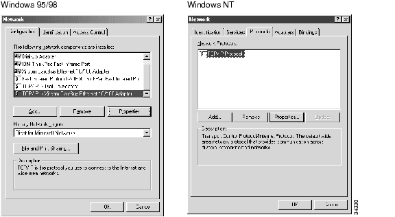
Figure 3-1 Network Dialog
Step 4
(a)
(b)
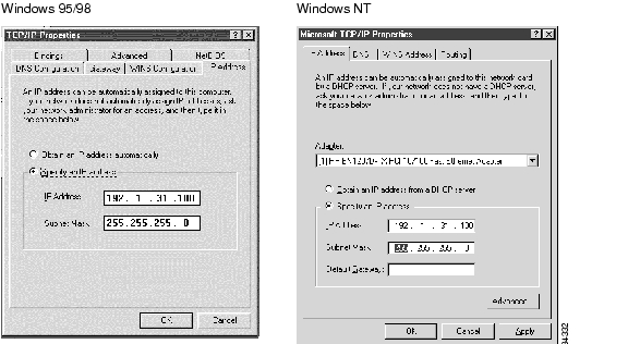
Step 5
Figure 3-2 IP Address Window
Step 6
Step 7
Step 8
Step 9
Step 10
Figure 3-3 TCP/IP Properties - Gateway Tab (Windows 95/98)
Step 11
Step 12
Step 13
Step 14
(a)
(b)
(c)
(d)
If your PC is not connected, a Request timed out message displays. If this occurs, check that the cables connecting the PC to the ONS 15454 are securely attached. Check the Link Status LED on the PC NIC card. Repeat Steps 1-14, verifying IP and submask information.
3.4.2 Local Area Network Connections
To access the ONS 15454 from a local area network (LAN):
•
•
•
•
If these conditions have been met, to access the ONS 15454, start your web browser and type the ONS 15454 IP address in the URL field.
Procedure: Disable Proxy Service: Windows with Internet Explorer
Step 1
Step 2
Step 3
Step 4
•
•
Procedure: Disable Proxy Service: Windows with Netscape
Step 1
Step 2
Step 3
Step 4
•
•
3.4.3 Remote Access to the ONS 15454
You can remotely access an ONS 15454 node using a LAN modem. The LAN modem must be connected to the RJ-45 port on a TCC card or to the LAN pins on the ONS 15454 backplane. The LAN modem must be properly configured for use with the ONS 15454. When the modem is installed, dial-up access to the ONS 15454 is available using a personal computer modem.
3.4.4 Connecting to the ONS 15454 with TL1 Terminals
Although the ONS 15454 is designed to be used with CTC, you can communicate with the ONS 15454 using TL1 commands or Telnet to port 2361. To connect a TL1 terminal (or a PC running terminal emulation software) to the ONS 15454, use the DB-9 plug on the front panel of the TCC or the CRAFT pins on the backplane. For a list of CRAFT pin assignments, see Table 1-3 on page 1-31. For information about TL1 commands that can be used with the ONS 15454, see Chapter 11, "TL1 Reference."
3.5 Logging into the ONS 15454
After you set up the physical connections between the PC and ONS 15454 and change your PC network settings, you can log into the CTC and begin setting up the ONS 15454 node.
Procedure: Log into the ONS 15454
Step 1
Step 2
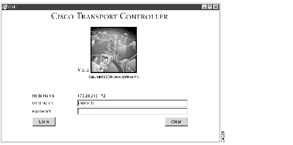
When the PC connects to the ONS 15454, the login window displays ( Figure 3-4).
Figure 3-4 Login Screen
Step 3
Note
After logging in, the CTC node view ( Figure 3-5) appears. From here, you can navigate to other CTC views to perform the ONS 15454 operations, administration, maintenance, and provisioning tasks described in the following sections.
Note
definition.
3.6 CTC Views
The CTC window includes a menu bar and a top and bottom pane. CTC provides three ONS 15454 views:
•
•
•
A graphic of the current view appears in the upper right portion of the CTC window. The node view displays the ONS 15454 shelf. The network view displays a background map with ONS 15454 nodes represented by colored squares. The card view displays a graphic of the selected card.
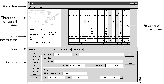
A thumbnail of the parent view is displayed in the upper left corner of the CTC window. Parent view is the level above the current view. For example, network view is the parent of node view, and node view is the parent of card view. Below the thumbnail, status information for the current view is shown. In node view, the Node name; IP address; session boot date and time; a summary of critical (CR), major (MJ), and minor (MN) alarms; the name of the user who is logged in; and the user's security level are shown. In network view, the status of the selected node or span is shown.
The middle of the CTC window provides tabs to access CTC functions. Some CTC tabs have subtabs, which are used to access subfunctions. The tabs that are displayed depend on the view. In node view, six tabs are displayed: Alarms, History, Circuits, Provisioning, Inventory, and Maintenance. In network view, only the Alarms, History, and Circuits tabs are displayed. CTC window elements are shown in .
Figure 3-5 CTC Window Elements
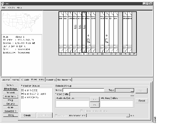
3.6.1 Node View
The CTC node view ( ) is displayed each time you log into CTC. Node view shows a real-time depiction of the ONS 15454 shelf. The colors of the cards, shown in , indicate the status of the physical card and slot.
Node view provides six tabs to access node information and perform node maintenance and provisioning tasks. Some tabs have subtabs. shows the CTC Node view with the Provisioning subtabs displayed. Node view tabs and subtabs are shown in .
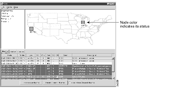
3.6.2 Network View
Network view ( Figure 3-6) displays information about the ONS 15454 network. You perform network provisioning and management tasks in this view. A United States map is displayed and the ONS 15454 nodes are represented by colored squares. The color of the square indicates the status of the node. shows the colors and their corresponding status.
Figure 3-6 Network View
The network view tabs display network alarms and alarm history and allow you to set up and edit network circuits. In addition, you can click spans (the lines connecting the nodes) and node icons on the network map to quickly view circuit properties, provision circuits, and perform protection switches. shows the actions that you can perform in network view.
Table 3-4 Network View Actions
Open a node
Any of the following:
•
•
•
Move a node icon
Pressing the Control <Ctrl> and left mouse buttons, drag the node icon to a new location.
Reset node icon position
Right click a node and choose Reset Position from the shortcut menu. The node icon moves to the position defined by the longitude and latitude fields on the General subtab.
Display span properties
Click a network span. Properties display in the upper left corner of the window.
Perform a UPSR protection switch for an entire span
Right click a network span and click Circuits. See the "Switch UPSR Traffic" section for UPSR protection switch procedures.
Provision a circuit
Right click a node and choose Provision Circuit from the shortcut menu. For circuit procedures, see the "Create a Circuit" section.
Update circuits with new node
Right click a node and choose Update Circuits With New Node from the shortcut menu. Use this command when you add a new node and want to pass circuits through the new node.
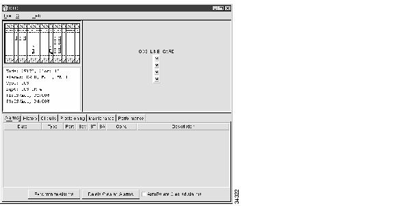
3.6.3 Card View
Card view displays information about individual ONS 15454 cards. ( shows an OC3 IR 4 1310 in card view.) You perform card-specific maintenance and provisioning tasks in card view. The information that is displayed and the tasks you can perform depend on the card. CTC displays a card view for all ONS 15454 cards except the TCC, XC, and XCVT cards.
Card view provides access to six tabs: Alarms, History, Circuits, Provisioning, Maintenance, and Performance. (The Performance tab is not displayed for the AIC card.) However, the subtabs, fields, and information displayed under each tab depend on the card type selected.
Figure 3-7 Card View
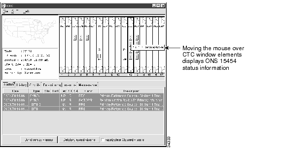
3.7 CTC Navigation
You can use different methods to navigate to views within the CTC window. You can select views from the Go To menu. You can also double click or right click objects in the window. Moving the mouse over nodes, cards, and card ports displays popup information about the node, card, or port. shows an example.
Figure 3-8 CTC Popup Information
Different methods for navigating within the CTC window are shown in .
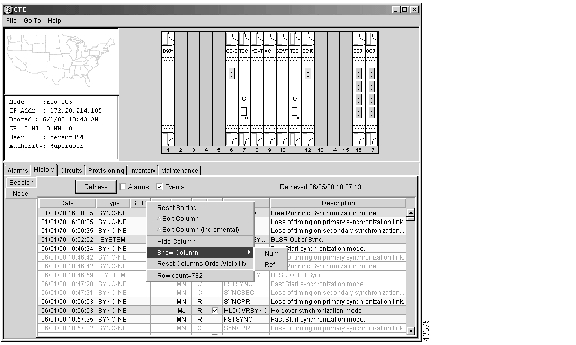
3.8 Viewing CTC Table Data
Much of the ONS 15454 data that CTC displays, such as alarms, alarm history, circuits, and node inventory, is displayed in tables. You can change the way the CTC tables are displayed. For example, you can:
•
•
•
To change CTC table display, left-click or right-click a table column header. Right clicking a column header displays a shortcut menu, shown in , with table column display options.
Figure 3-9 Table Column Shortcut Menu
lists the options that you can use to customize information display in CTC tables.
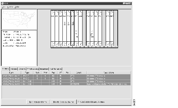
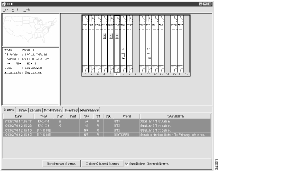
3.9 Viewing ONS 15454 Alarms
Select the Alarms tab ( ) to display current and cleared alarms generated on the node. shows the information that is displayed for each ONS 15454 alarm.
Table 3-7 Alarm Data
Num
Unique, per-node alarm identifier (this column is hidden by default)
Ref
If an alarm references another alarm, the number of the referenced alarm (this column is hidden by default)
Date
Date and time of the alarm
Node
Node where the alarm occurred, based on the active TCC (displays in network view only)
Type
Type of alarm, based on circuit type
Slot
Slot where the alarm occurred
Port
Port where the alarm occurred
Sev
Severity level: CR (critical), MJ (major), MN (minor), NA (not alarmed), NR (not reported)
ST
Status: R (raised), C (clear)
SA
When checked, indicates the alarm is service affecting
Cond
The error message code. See Chapter 9, "CTC Alarms" for troubleshooting procedures
Description
Description of the alarm
Figure 3-10 Alarms Tab
Alarms are displayed in one of five background colors, listed in , to quickly communicate the alarm severity. For information about troubleshooting alarms, see Chapter 9, "CTC Alarms."
Table 3-8 Alarm Colors
Red
Critical Alarm
Orange
Major Alarm
Yellow
Minor Alarm
Blue
Event Notification (not an alarm)
White
Cleared alarm or event
3.9.1 Controlling Alarm Display
You can control the display of alarms on the Alarms tab. shows the actions you can perform from the Alarms tab.
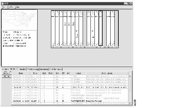
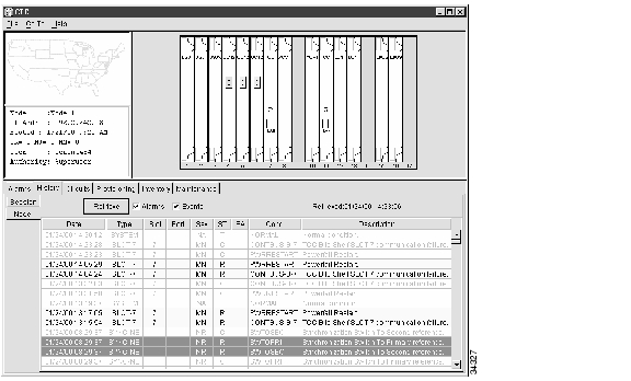
3.9.2 Viewing Alarm History
The History tab displays historical alarm data. The History tab also shows the events (that is, non-reported activities) that occur in addition to the alarms. For example, protection switching events or performance monitoring threshold crossings appear here. The History tab presents two alarm history views:
•
•
Tip
Figure 3-11 History>Session Subtab
Figure 3-12 History>Node Subtab
3.9.3 Setting Up General Node Information
The first ONS 15454 provisioning task you will perform is setting up basic node information. If the node is to be connected to a LAN or other ONS 15454s, the information that you enter for the node, such as node name and IP address, must be coordinated with your network administrator.
Procedure: Set Up General Node Information
Step 1
Step 2
Step 3
•
•
•
•
•
CTC uses the latitude and longitude to place node icons on the network view map. To convert longitudes and latitudes given in degrees to degrees, minutes, and seconds, see the "Convert Coordinates to Degrees, Minutes, and Seconds" section.
•
•
•
•
Step 4
CTC uses the longitude and latitude you enter on the General subtab to place node icons on the network view map. You can obtain the longitude and latitude for cities and Zip Codes from the US Census Bureau U.S. Gazetteer website (www.census.gov/cgi-bin/gazetteer). Coordinates are generally provided in degrees. CTC requires that you enter coordinates in degrees, minutes, and seconds. Use the following procedure to convert coordinates.
Procedure: Convert Coordinates to Degrees, Minutes, and Seconds
Step 1
Step 2
Step 3
Step 4
Step 5
Step 6
Step 7
3.9.4 Setting Up ONS 15454 Network Information
Before you connect an ONS 15454 to other ONS 15454s or to a LAN, you must change the default IP address that is shipped with the ONS 15454 (192.1.0.2). IP addresses are unique identifiers for nodes or hosts connected to a network using TCP/IP. Each address consists of a network number and a host number. The network numbers are used for routing, while the host number is used to address an individual host within the network or subnetwork. A subnet mask is used to extract network and host information from the IP address.
IP addresses are 32-bit binary numbers. However, to make IP addresses easier to work with, they are represented as four decimal values, each representing eight bits in the range 0 to 255 (known as octets) separated by decimal points. For example, the following IP address is in binary format:
10001100.10110011.11011100.11001000The same address, represented as four decimal values, is:
140.179.220.200Because the IP addresses that you work with represent binary addresses, changing an address is not always straightforward. Therefore, before you change the ONS 15454 IP addresses, consult your LAN administrator or someone knowledgeable in TCP/IP to ensure addresses are suitable to your network. Additional information about ONS 15454 network management and Ethernet applications is provided in Chapters 7 and 8.
Use the following procedure to set up networking information for the ONS 15454. If the ONS 15454 or the computer used to access the ONS 15454 is linked to a network router, you should create a static route, which can be provisioned using the Static Route fields.
Procedure: Set Up Network Information
Step 1
Step 2
•
•
•
•
•
•
Figure 3-13 Provisioning>Network Subtab
Step 3
Step 4
The TCCs will reboot, one at a time.
3.9.5 Setting Up ONS 15454 Security
The ONS 15454 has four security levels that limit the functions users can perform: Retrieve, Maintenance, Provisioning, and Superuser. A Retrieve user can retrieve and view CTC information but cannot set or modify parameters. A Maintenance user can access only Maintenance options. A Provisioning user can access only Provisioning and Maintenance options. A Superuser, usually the network element administrator, can perform all of the functions of the other security levels as well as set names, passwords, and security levels for other users. A list of CTC actions that can be performed at each security level is shown in .
Note
Security levels also limit the amount of time a user can leave the system idle before the CTC window is locked to prevent unauthorized users from making changes. Higher security levels have shorter idle times. shows CTC security levels and their idle times.
Table 3-11 ONS 15454 Security Idle Times
Retrieve
Unlimited
Maintenance
60 minutes
Provisioning
30 minutes
Superuser
15 minutes
Procedure: Create New Users
Step 1
Step 2
Step 3
Step 4
•
•
•
•
Figure 3-14 Create User Dialog
Step 5
Note
Procedure: Edit User Security
Step 1
Step 2
Step 3
Step 4
Step 5
Note
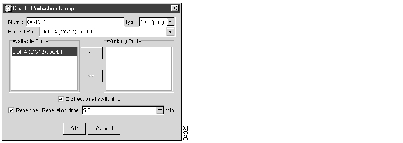
3.9.6 Creating Protection Groups
The ONS 15454 provides several card protection methods. When you set up protection for ONS 15454 cards, you must choose between maximum protection and maximum card slot availability. The highest protection reduces the number of available card slots; the highest card slot availability reduces the protection. shows the protection types that can be set up for ONS 15454 cards.
Procedure: Create Protection Groups
Step 1
Step 2
Step 3
Step 4
•
•
•
Based on these selections, a list of available working cards or ports is displayed under Available Cards or Available Ports.
Figure 3-15 Create Protection Group Dialog (1+1)
Step 5
Step 6
•
•
•
Step 7
Procedure: Edit Protection Groups
Step 1
Step 2
Figure 3-16 Provisioning>Protection Subtab
Step 3
Step 4
Step 5
Procedure: Delete Protection Groups
Step 1
Step 2
(a)
(b)
(c)
Step 3
Step 4
Step 5
3.9.7 Setting Up ONS 15454 Timing
You must set the SONET timing parameters for each ONS 15454. ONS 15454 timing is set to one of two modes: external or line. In typical ONS 15454 networks, at least one node is set to external and the other nodes are set to line. The external node derives its timing from a Building Integrated Timing Supply (BITS) source wired to the BITS backplane pins. ( Figure 1-20 shows a diagram of the BITS pin location.) The BITS source, in turn, derives its timing from a Primary Reference Source (PRS) such as a Stratum 1 clock or GPS signal. The line nodes derive timing from Optical Carrier cards.
For protection, up to three timing references can be identified. These are typically two BITS-level or line-level sources and an internal reference. The internal reference is the Stratum 3 (ST3) clock provided on every ONS 15454 TCC card.
shows an ONS 15454 network timing setup example. Node 1 is set to external timing. Two references are set to BITS. These are Stratum 1 timing sources wired to the node's BITS input pins on the ONS 15454 backplane. Its third reference is set to internal. The BITS output pins on the backplane of Node 3 are used to provide timing to outside equipment, such as a Digital Access Line Access Multiplexer.
Figure 3-17 ONS 15454 Timing Example
Synchronization Status Messaging (SSM) is a SONET protocol that communicates information about the quality of the timing source. SSM messages are carried on the S1 byte of the SONET Line layer. They enable SONET devices to automatically select the highest quality timing reference and to avoid timing loops.
SSM messages are either Generation 1 or Generation 2. Generation 1 is the first and most widely deployed SSM message set. Generation 2 is a newer version. If you enable SSM for the ONS 15454, consult your timing reference documentation to determine which message set to use. and show the Generation 1 and Generation 2 message sets.
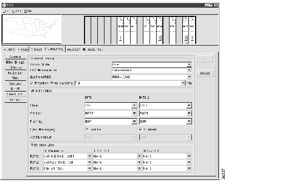
Procedure: Setup ONS 15454 Timing
Step 1
Step 2
•
•
•
•
•
The BITS Facilities section sets the parameters used by your BITS1 and BITS2 timing references. Many of these settings are determined by the timing source manufacturer.
•
•
•
•
•
Reference fields define up to three timing references for the node and up to six BITS Out references. BITS Out references define the timing references used by equipment that can be attached to the node's BITS Out pins on the backplane. If you attach equipment to BITS Out, you normally attach it to a Line mode node because equipment near the External timing reference can be directly wired to the reference.
•
•
Figure 3-18 Provisioning>Timing Subtab
Step 3
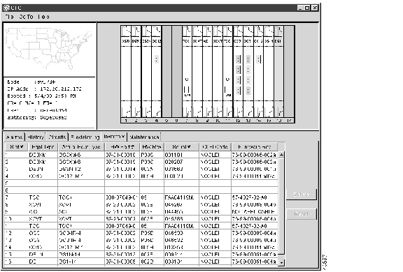
3.10 Viewing ONS 15454 Inventory
The Inventory tab ( ) displays information about cards installed in the ONS 15454 node including part numbers, serial numbers, hardware revisions, and equipment types. The tab provides a central location to obtain information and to determine applicability of ONS 15454 Product Change Notices (PCNs) and Field Service Bulletins (FSBs). Using the ONS 15454 export feature, you can export inventory data from ONS 15454 nodes into spreadsheet and database programs, where information can be consolidated for network inventory management and reporting.
Figure 3-19 Inventory Tab
The Inventory tab displays the following information about the cards installed in the ONS 15454:
•
•
•
Note
•
•
•
•
•
3.11 Printing and Exporting CTC Data
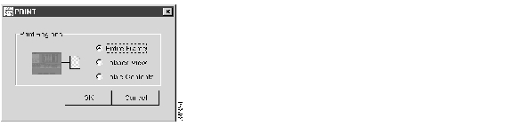
You can print CTC windows and you can print CTC data that is displayed in columns, such as alarms and inventory. You can also export CTC table data in formats that can be used use by other applications such as spreadsheets, word processors, and database management applications. shows CTC data that can be exported.
Procedure: Print CTC Data
Use the following procedure to print CTC screens and data. Before you start, make sure your PC is connected to a printer.
Step 1
Step 2
•
•
•
Figure 3-20 CTC Print Dialog
Step 3
Step 4
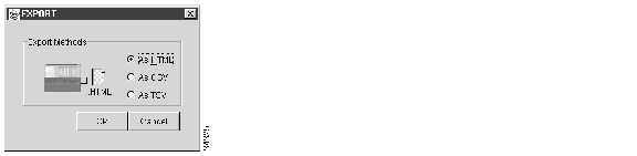
Procedure: Export CTC Data
Step 1
Step 2
•
•
•
Figure 3-21 CTC Export Dialog
Step 3
Step 4
•
•
•
Step 5
Step 6
3.12 Displaying CTC Data in Other Applications
You can display CTC data exported in HTML with any web browser application, such as Netscape Navigator or Microsoft Internet Explorer. To display the data, use the web browser's File/Open command to open the CTC data file.
You can display CTC data exported as comma separated values (CSV) or tab separated values (TSV) in text editors, word processors, spreadsheets, and database management applications. Although procedures depend on the application, you typically can use File/Open to display the CTC data. Text editors and word processors display the data exactly as it is exported. Spreadsheet and database management applications display the data in cells. You can then format and manage the data using the spreadsheet or database management application tools.
![]()
![]()
![]()
![]()
![]()
![]()
![]()
![]()
Posted: Mon Feb 25 07:48:22 PST 2008
All contents are Copyright © 1992--2008 Cisco Systems, Inc. All rights reserved.
Important Notices and Privacy Statement.