|
|

Table Of Contents
8.1 Simple Network Management Protocol
8.1.6 SNMP Remote Network Monitoring
8.2 IP Address Entry Using Front Panel LCD
8.4.2 Common IP Addressing Scenarios with the ONS 15454
8
Network Management
This chapter explains concepts related to network management with the ONS 15454. It includes Simple Network Management Protocol (SNMP), front panel LCD IP entry, Proxy ARP, IP addressing and subnets, IP troubleshooting, and Static Route Provisioning.
8.1 Simple Network Management Protocol
Simple Network Management Protocol (SNMP) is an application-layer Internet Protocol (IP) that allows network devices to exchange management information. SNMP enables network administrators to manage network performance, find and solve network problems, and plan for network growth.
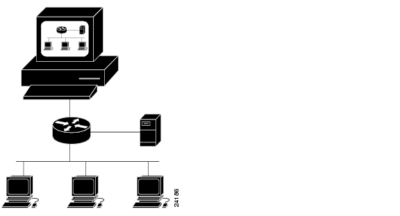
The Cisco ONS 15454 supports SNMP Version 1 (SNMPv1) and SNMP Version 2c (SNMPv2c). Both versions share many features, but SNMPv2c offers additional protocol operations. This section describes both versions and explains how to configure SNMP on the ONS 15454. illustrates a basic network managed by SNMP.
Figure 8-1 Basic Network Managed by SNMP
8.1.1 SNMP Basic Components
An SNMP-managed network consists of three primary components: managed devices, agents, and management systems. A managed device is a network node that contains an SNMP agent and resides on a managed network. Managed devices collect and store management information and use SNMP to make this information available to management systems that use SNMP. Managed devices include routers, access servers, switches, bridges, hubs, computer hosts, and printers.
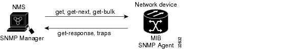
An agent is a software module that resides in a managed device. An agent has local knowledge of management information and translates that information into a form compatible with SNMP. The SNMP agent gathers data from the management information base (MIB), which is the repository for information about device parameters and network data. The agent can also send traps, or notification of certain events, to the manager. illustrates these SNMP operations.
Figure 8-2 SNMP Operations
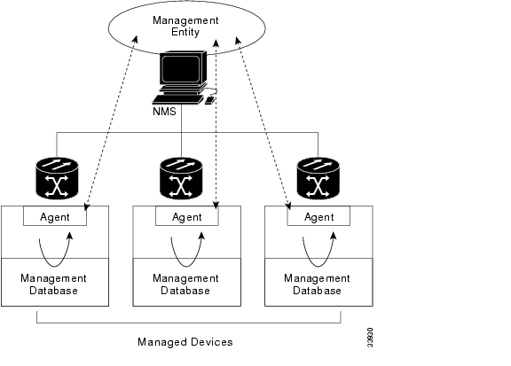
A management system executes applications that monitor and control managed devices. Management systems provide the bulk of the processing and memory resources required for network management. One or more management systems must exist on any managed network. illustrates the relationship between the three key SNMP components.
Figure 8-3 SNMP Components
8.1.2 SNMP Support
The ONS 15454 supports SNMP v1 and v2c traps and gets. The SNMP MIBs in the ONS 15454 define alarms, traps, and status. Through SNMP, network management system (NMS) applications can query a management agent using a supported MIB. The functional entities include an Ethernet switch, SONET multiplexer, and many others. SNMP can access the ONS 15454 through the Timing Communication and Control (TCC) card Ethernet port, the backplane LAN wire-wrap, or SONET Data Communication Channel (SDCC).
Procedure: Set up SNMP Support
Step 1
On the Cisco Transport Controller (CTC) window, click the Provisioning tab.
Step 2
Step 3
The Create SNMP Trap Destination dialog opens ( Figure 8-4).
For a description of SNMP traps, see the "SNMP Traps" section.
Figure 8-4 Create SNMP Trap Destination Dialog
Step 4
Step 5
For a description of SNMP community names, see the "SNMP Community Names" section.
Note
Note
Step 6
Refer to your NMS documentation to determine whether to use SNMP v1 or v2.
Step 7
Note
Step 8
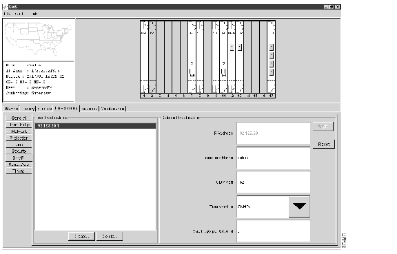
SNMP settings are now configured. To view SNMP information for each node, click the IP address of a node on the Trap Destinations screen ( Figure 8-5).
Figure 8-5 Trap Destinations Screen
8.1.3 SNMP MIBs
A Management Information Base (MIB) is a hierarchically-organized collection of information. MIBs are accessed using a network-management protocol such as SNMP. They are comprised of managed objects and are identified by object identifiers.
The ONS 15454 SNMP manager uses information in the MIB to perform the operations described in Table 8-1
.
1.With this operation, an SNMP manager does not need to know the exact variable name. A sequential search is performed to find the needed variable from within the MIB.
A managed object (sometimes called a MIB object) is one of any number of specific characteristics of a managed device. Managed objects are comprised of one or more object instances that are essentially variables.
The ONS 15454 MIBs ship on the accompanying software CD. These MIBs need to be compiled in the following order. If the order is not followed, one or more MIB files may not compile.
1
2
3
If you are unable to compile the ONS 15454 MIBs, call the Technical Assistance Center (TAC) at 1-877-323-7368.
8.1.4 SNMP Traps
The ONS 15454 can receive SNMP requests from a number of SNMP managers and send traps to ten trap receivers. The ONS 15454 generates all alarms and events as SNMP traps.
Traps generated by the ONS 15454 contain an object ID that uniquely identifies the alarm. An entity identifier uniquely identifies which entity generated the alarm (slot, port, STS, VT, BLSR, STP, etc.). The traps give the severity of the alarm (critical, major, minor, event, etc.) and indicate whether the alarm is service affecting or non-service affecting. The traps also contain a date/time stamp that shows the date and time the alarm occurred. The ONS 15454 also generates a trap for each alarm when the alarm condition clears.
Each SNMP trap contains seven variable bindings ( ).
The ONS 15454 supports generic and Internet Engineering Task Force (IETF) traps. The generic traps are listed in . IETF-supported traps are listed in .
8.1.5 SNMP Community Names
You can provision community names for all SNMP requests from the SNMP Trap Destination window in CTC (see the "Set up SNMP Support" section). In effect, any SNMP request using a community name that matches a community name on the list of provisioned SNMP trap destinations is considered valid. Otherwise, the request is considered invalid and is dropped.
If an SNMP request contains an invalid community name, the request is silently dropped and the MIB variable, snmpInBadCommunityNames, is incremented. All SNMP requests containing a validated community name are granted access to all MIB variables managed by the agent.
8.1.6 SNMP Remote Network Monitoring
The ONS 15454 incorporates Remote Monitoring (RMON) to allow network operators to monitor the ONS 15454's E100 and E1000 cards. This feature is not apparent to the typical CTC user, because RMON interoperates with a network management application. However, with CTC the user can provision the RMON alarm thresholds (see the "Remote Monitoring Specification Alarm Thresholds" section on page 7-69). The CTC also monitors the five RMON groups implemented by the ONS 15454.
The ONS 15454 RMON implementation is based on the IETF standard MIB Request for Comment (RFC)1757. The ONS 15454 implements five groups from the standard MIB: Ethernet Statistics, History Control, Ethernet History, Alarm, and Event.
8.1.6.1 Ethernet Statistics Group
The Statistics group contains the basic statistics for each monitored subnetwork in a single table named etherstats.
8.1.6.2 History Control Group
The History Control group defines sampling functions for one or more monitor interfaces. RFC 1757 defines the historyControlTable.
8.1.6.3 Ethernet History Group
RFC 1757 defines the etherHistoryTable. The etherHistoryTable will be implemented as defined in RFC 1757, within the bounds of the historyControlTable.
8.1.6.4 Alarm Group
The alarm group consists of a single alarm table. This table provides the network performance alarm thresholds for the network management application.You can provision the thresholds in the table with CTC.
8.1.6.5 Event Group
The event group consists of two tables, evenTable and logTable. The evenTable is read-only. The logTable is implemented as specified in RFC 1757.
8.2 IP Address Entry Using Front Panel LCD
Users can set up the IP address, subnet mask, and default router addresses of the ONS 15454 using the slot, status, and port buttons on the front panel LCD (see ). This allows users to accomplish these basic operations without a computer.
Note
Figure 8-6 Front Panel LCD
Procedure: Enter IP Address Using Front Panel LCD
Note
Step 1
Step 2
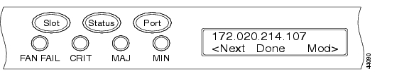
Figure 8-7 IP Address Option
Step 3
Figure 8-8 IP Address LCD Screen
Step 4
Step 5
Step 6
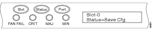
Figure 8-9 Save Configuration Option LCD Screen
Step 7
Step 8
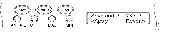
Figure 8-10 Save and REBOOT LCD Screen
The Save and REBOOT screen appears ( ).
Step 9
Figure 8-11 Saving Changes LCD Screen
Saving a new configuration reboots the TCC cards. The Saving Changes LCD appears for several minutes while the TCC cards reboot ( ). When the LCD screen returns to the normal alternating display mode, the procedure is complete.
8.3 Proxy ARP
Proxy Address Resolution Protocol (ARP) enables a LAN-connected gateway ONS 15454 to automatically handle ARP requests for remote non-LAN ONS 15454s connected via DCC to the gateway ONS 15454. Proxy ARP requires no configuration from the user and eliminates the need for the user to set up static host routes.
Proxy ARP works by having a single LAN-connected ONS 15454 proxy for remote ONS 15454s. If a device on the LAN sends an ARP request intended for one of the DCC-connected ONS 15454s, then the gateway ONS 15454 ONS 15454 returns its own MAC address to the LAN device (proxies). The LAN device then sends the datagram intended for the remote ONS 15454 to the MAC address of the proxy ONS 15454. The proxy ONS 15454 forwards this data to the remote 15454 using its own ARP table. The ARP table matches IP addresses with the MAC IDs of remote ONS 15454s and is built through internal OSPF routing protocol. illustrates Proxy ARP.
Figure 8-12 ONS 15454 Network Using Proxy ARP
Note
8.4 IP Addressing and Subnets
This section provides IP addressing guidelines for the ONS 15454. The IP addressing information includes IP addressing classes and IP configuration scenarios.
8.4.1 Types of IP Addresses
IP addresses are categorized as either Class A, B, or C. The different classes refer primarily to how the addresses may be used and how many subnets and hosts will be available for use in the network.
Each network needs its own, unique network number and each host within a network needs a unique host number.
Subnetting is used to maximize the number of networks available within a range (class) of addresses. Each class of address allows a different number of subnets to be configured.
8.4.1.1 Class A Addresses and Subnets
In a class A IP address, the first eight bits are used for the network ID, and the last 24 bits are used for the host ID. The first bit of a network address will be 0 when the number is converted to binary. For example, 5.xxx.xxx.xxx = 00000101 (5). The maximum number of network addresses that can be derived in class A is 126; the maximum number of hosts is 16,777,214. The address 0.0.0.0 is reserved as the default route and 127.xxx.xxx.xxx is reserved as the loopback address. The natural mask is 255.0.0.0 and the available addresses are 1.xxx.xxx.xxx through 126.xxx.xxx.xxx.
8.4.1.2 Class B Addresses and Subnets
In a class B IP address, the first 16 bits are used for the network ID and the last 16 bits are used for the host ID. The first two bits of a network address begin with 10 when the number is converted to binary. For example, 128.x.x.x = 10000000. The maximum number of network addresses that can be derived from class B is 16,384; the maximum number of hosts is 65,534. The natural mask is 255.255.0.0 and the available addresses are 128.0.xxx.xxx through 191.255.0.0.
8.4.1.3 Class C Addresses and Subnets
In a class C IP address, the first 24 bits are used for the network ID and the last eight bits are used for the host ID. The first two bits of a network address begin with 11 when the number is converted to binary. For example, 192.x.x.x = 11000000. The maximum number of network addresses that can be derived from class C is 2,097,152; the maximum number of hosts is 254. The natural mask is 255.255.255.0 and the available addresses are 192.0.0.xxx through 223.255.255.xxx.
8.4.2 Common IP Addressing Scenarios with the ONS 15454
ONS 15454 IP addressing generally has seven common IP addressing scenarios or configurations. Refer to the following illustrations and checklists when setting IP addresses and configuring subnets. You must be able to answer yes to each checklist question to be sure that all IP addressing guidelines are met. The following figures illustrate these seven scenarios and provide an IP checklist for each scenario.
Note
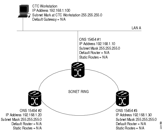
8.4.2.1 IP Scenario 1
ONS 15454s and CTC are on the same subnet; all ONS 15454s attach to LAN A.
If you answer No to any of the questions in the checklist see the "IP Troubleshooting" section.
Figure 8-13 IP Addressing Scenario 1
Procedure: IP Checklist for Scenario 1
•
•
•
•
•
•
•
•
•
•
•
•
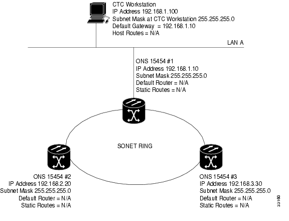
8.4.2.2 IP Scenario 2
ONS 15454s and CTC are on different subnets; all ONS 15454s attach to LAN B.
If you answer No to any of the questions in the checklist see the "IP Troubleshooting" section.
Figure 8-14 IP Addressing Scenario 2
Procedure: IP Checklist for Scenario 2
•
•
•
•
•
•
•
•
•
•
•
•
•
•
•
•
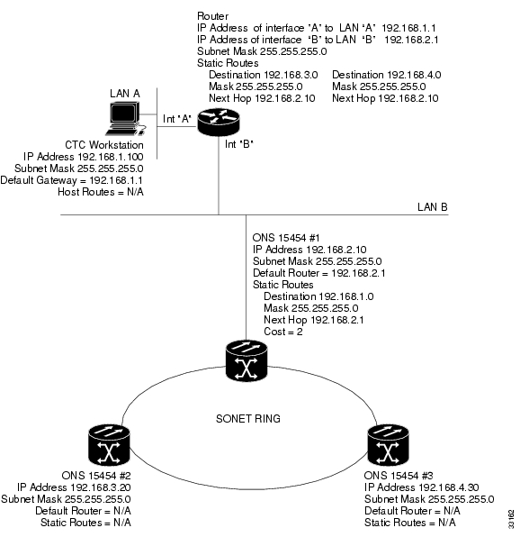
8.4.2.3 IP Scenario 3
CTC and all ONS 15454s are on the same subnet; ONS 15454 #1 is attached to LAN A and ONS 15454 #2 and #3 are at remote sites
If you answer No to any of the questions in the checklist, see the "IP Troubleshooting" section.
Figure 8-15 IP Addressing Scenario 3
Procedure: IP Checklist for Scenario 3
•
•
•
•
(ONS 15454 #2 and #3)?•
•
•
•
•
•
•
•
•
•
•
•
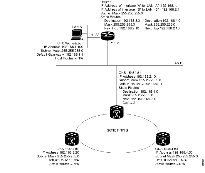
8.4.2.4 IP Scenario 4
CTC and ONS 15454 #1 are on the same subnet, while ONS 15454 #2 and # 3 are on different subnets; ONS 15454 #1 is attached to LAN A and ONS 15454 #2 and #3 are at remote sites.
If you answer No to any of the questions in the checklist, see the "IP Troubleshooting" section.
Figure 8-16 IP Addressing Scenario 4
Procedure: IP Checklist for Scenario 4
•
•
•
•
•
•
•
•
•
•
•
•
•
•
•
•
•
8.4.2.5 IP Scenario 5
CTC and each of the ONS 15454s are on different subnets; ONS 15454 #1 is attached to LAN A and ONS 15454 #2 and #3 are at remote sites.
If you answer No to any of the questions in the checklist, see the "IP Troubleshooting" section.
Figure 8-17 IP Addressing Scenario 5
Procedure: IP Checklist for Scenario 5
•
•
•
•
•
•
•
•
•
•
•
•
•
•
•
•
•
•
•
•
•
8.4.2.6 IP Scenario 6
CTC is on a different subnet and all ONS 15454s are on the same subnet; ONS 15454 #1 attached to LAN A and ONS 15454 #2 and #3 are at remote sites.
If you answer No to any of the questions in the checklist, see the "IP Troubleshooting" section.
Figure 8-18 IP Addressing Scenario 6
Procedure: IP Checklist for Scenario 6
•
•
•
•
•
•
•
•
•
•
•
•
•
•
•
•
•
•
•
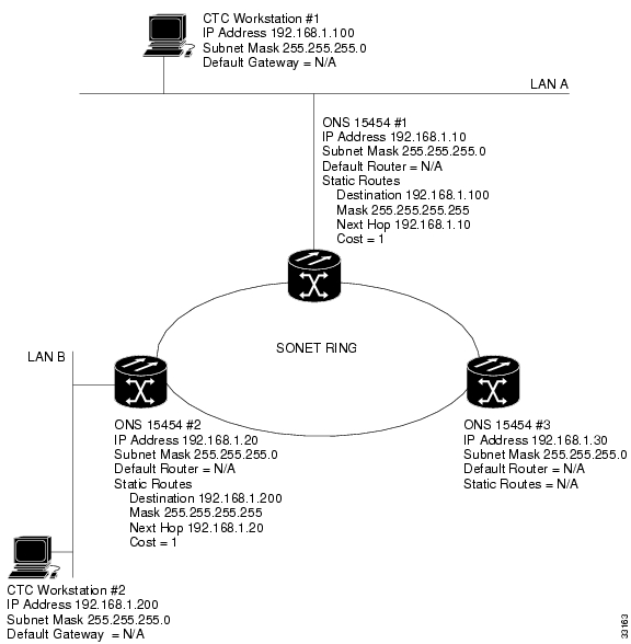
8.4.2.7 IP Scenario 7
CTC #1 and #2 and all ONS 15454s are on the same IP subnet; ONS 15454 #1 and CTC #1 are attached to LAN A. ONS 15454 #2 and CTC #2 are attached to LAN B.
If you answer No to any of the questions in the checklist, see the "IP Troubleshooting" section.
Figure 8-19 IP Addressing Scenario 7
Procedure: IP Checklist for Scenario 7
•
•
•
•
•
•
•
•
•
•
•
•
•
•
•
•
•
8.5 IP Troubleshooting
Look for solutions in the following section if you answered No to any of the questions in the IP scenarios checklists or encounter any of the listed IP problems.
Table 8-6 IP Troubleshooting Solutions
The workstation running the CTC cannot ping itself.
•
•
There is no link integrity between the workstation and the hub/switch.
•
•
•
•
•
•
No link integrity exists between the hub/switch and the ONS 15454's LAN wire-wraps or RJ-45 port.
•
•
•
•
•
You do not know if the hub/switch port that connects to the ONS 15454(s) is properly set at 10 Mbps half-duplex.
•
Although the workstation is capable of pinging other devices sucessfully, it cannot ping a specific ONS 15454.
•
•
•
The Java policy file was not installed or it was installed before the Java plug-in.
•
•
You do not know whether the IP addresses of ONS 15454s #X, #Y and #Z lie on the same or different subnets?
•
It is not known whether the default router entry for the ONS 15454 is set correctly to match the IP address of the router's B interface.
•
•
•
•
No link integrity exists between the router ports and the hub/switches.
•
You do not know if the optical trunk ports on the ONS 15454s are in service.
•
Click the Provisioning tab.
Click the Line subtab.
Click Status column.
Verify the ports are set to In Service.
You do not know if the DCC is enabled on in-service optical trunk ports.
•
Go to the card level view of the optical card.
Click the Provisioning tab.
Click the Sonet DCC subtab.
Verify that the optical cards are listed.
The web browser will not connect to the ONS 15454, but connects successfully to other sites.
•
•
Unable to ping remote ONS 15454s.
•
•
8.6 Static Route Provisioning
The ONS 15454 provisions static network routes in the ONS 15454 network element through the CTC. This makes it possible to have multiple CTC sessions, with different destination IP addresses, on a network of ONS 15454s that all lie on the same subnet. For example, a Network Operations Center (NOC) may be remotely monitoring an ONS 15454 through CTC, while at the same time an on-site employee is logged into an ONS 15454 on the network with a separate CTC session. It also allows workstations to connect to ONS 15454s through routers.
To achieve CTC connectivity, interconnected ONS 15454 network elements use the SONET DCC (SDCC) for communication. Communication is accomplished using a combination of the Open Shortest Path First (OSPF) routing protocol and manually-entered static routes.
The CTC adds static route entries to the network element's routing table. This routing table information is advertised to the other ONS 15454s connected by DCCs.
Adding static route provisioning on the ONS 15454 requires configuration changes in the network elements and CTC workstations. Only one example is given below. For other typical IP addressing scenarios, see the "Common IP Addressing Scenarios with the ONS 15454" section. These scenarios contain additional details on router and CTC workstation setup that support the configurations described below.
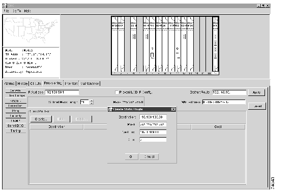
Procedure: Provision Static Routing to a Router Linked Workstation
This procedure provisions a static route to connect an ONS 15454 through a router and to a CTC workstation. All networks in this example use a 24-bit subnet mask. The CTC workstation IP address is 192.168.100.20, the ONS 15454 IP address is 192.168.90.11, and the IP address of the router port on the same segment as the ONS 15454 is 192.168.90.1.
Step 1
Step 2
Step 3
Step 4
The Create Static Route dialog opens (see Figure 8-20 ).
Figure 8-20 Create Static Route Window
Step 5
Step 6
Step 7
Step 8
Note
Step 9
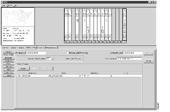
Step 10
Figure 8-21 Static Route Window
Note
![]()
![]()
![]()
![]()
![]()
![]()
![]()
![]()
Posted: Mon Feb 25 07:33:23 PST 2008
All contents are Copyright © 1992--2008 Cisco Systems, Inc. All rights reserved.
Important Notices and Privacy Statement.