|
|

Table Of Contents
4.1 Management Modes and Configuration
4.1.1 Management Port Configuration
4.1.3 IP Default Gateway Configuration
4.2.2 Scenario 1: Cisco Edge Craft and ONS 15305 on the Same Subnet
4.2.3 Scenario 2: Cisco Edge Craft and ONS 15305 on Different Subnets
4.3.2 Identify the Network Element
4.3.5 Available Features (Licenses)
4.3.6 Physical Inventory - ONS 15305
4.3.7 Physical Inventory - ONS 15302
4.3.10 Logs (Alarm Logs, Performance Data Logs)
4.4 Synchronization Management
4.4.3 View the Synchronization Data (T0 or T4)
4.4.4 Add Synchronization Source Candidate (T0 or T4)
4.4.5 Modify Synchronization Source Candidate (T0 or T4)
4.4.6 Delete Synchronization Source Candidate (T0 or T4)
4.4.7 Operate Synchronization Switch (T0 or T4)
4.4.8 View Synchronization Switch (T0 or T4)
4.4.9 Activate Synchronization on the ONS 15302
4.5 Download Software to a Network Element
4.5.2 Operational and Administrative Software Bank
4.5.3 Effect of Software Upgrades on Traffic
4.5.4 Download an ONS 15305 Network Release
4.5.5 Download Software to the ONS 15305
4.5.6 Download Software to the ONS 15302
4.6 Back Up and Restore Configuration Data
4.6.1 Back Up Configuration Data
4.6.2 Restore Configuration Data
4.7 Alarm and Event Configuration
4.7.2 Configure General Alarm Reporting
4.7.3 Suppress Specific Alarms
4.7.4 Modify Alarm Severity and Description
4.7.5 Set Signal Degrade Threshold
4.7.6 Modify Alarm Persistency
4.7.7 Modify ONS 15302 Alarm Configuration Attributes
General Management
This chapter describes the configuration operations supported by the Management Interface managed object (MO).
The attributes under the management interfaces MO are not unique in the information model. Each attribute mirrors a similar attribute located under another MO. The attributes under the management interfaces MO have been put together to allow the user to set up basic configuration of the management interfaces without having to browse through many MOs in the topology browser. For advanced configuration operations, additional MOs must still be used.
4.1 Management Modes and Configuration
The management traffic is IP based (SNMP and TFTP messages); therefore when configuring a management path IP datagrams must carry the management traffic over the network. For the management interfaces, two main encapsulation types are available:
•
IP directly carried over a layer 2 protocol (Ethernet, PPP, or proprietary).
•
In addition, each management interface can be turned off. Actual encapsulation support varies depending on the management interface type (management port or DCC). Table 4-1 provides an overview of the different management modes versus the management interfaces.
Note
Table 4-1 Management Modes Versus Management Interface
Management Port
X
X
DCC
X
X
X
Note
The following sections describe how to configure the management port and the DCCs by using the management interfaces MO present in the topology browser.
4.1.1 Management Port Configuration
The management port can run two types of encapsulation or mode. A particular mode is selected by setting the variable mode (management interfaces >management port > mode). Required configuration for possible modes is Not Used or IP.
4.1.1.1 Mode: Not Used
To configure the management port mode to Not Used complete the following steps.
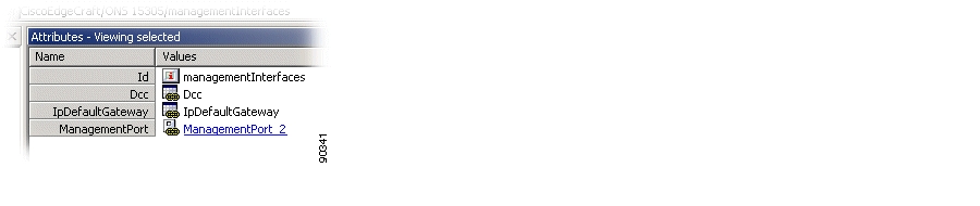
Step 1
Figure 4-1 Management Interfaces - Managed Object
.
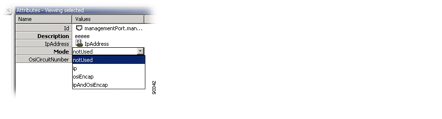
Step 2
Figure 4-2 ManagementPort - Attributes
Step 3
Figure 4-3 ManagementPort - Mode Selector
.
Step 4
4.1.1.2 Mode: IP
To configure the management port with the mode set to IP, complete the following steps:
Step 1
Step 2
Step 3
Step 4
Step 5
Figure 4-4 ManagementPort - IP Address Attribute
.
Step 6
Figure 4-5 ManagementPort - Add IP Address
.
Step 7
Depending on your topology, additional routing information might need to be configured. You can define static routes or control dynamic protocols (RIP, OSPF) by using the IP managed object in the topology browser. Defining a default gateway can be done directly from the management interface's managed object as explained in section "IP Default Gateway Configuration" section.
4.1.2 DCC Configuration
A DCC can run three types of encapsulation or mode. A particular mode is selected by setting the variable mode (management interfaces > DCC > mode). The required configuration for one of the two possible modes (Not Used or IP) is further detailed in the next sections.
4.1.2.1 Mode: Not Used
To configure a DCC with the mode set to Not Used, complete the following steps.
Step 1
Step 2
Step 3
Step 4
4.1.2.2 Mode: IP
To configure a DCC with the mode set to IP, complete the following steps.
Step 1
Step 2
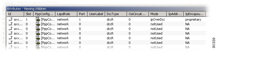
Step 3
Figure 4-6 Management Interfaces - Dcc Attribute
.
Step 4
Figure 4-7 IPEcapsulation - Encapsulation Selector
.
Step 5
Step 6
Step 7
Step 8
If the mode is set to IP and ipEncapsulation is set to PPP, additional configuration for PPP can be performed via the pppConfiguration variable (management interfaces > DCC > pppConfiguration).
Depending on your topology, additional routing information might need to be configured. You can define static routes or control dynamic protocols (RIP, OSPF) by using the IP managed object in the topology browser. Defining a default gateway can be done directly from the management interfaces managed object as explained in "IP Default Gateway Configuration" section.
4.1.3 IP Default Gateway Configuration
To configure an IP default gateway on the network element complet ethe following steps.
Step 1
Step 2
Step 3
Step 4
Note
Modifying the default gateway results in removing the previous default gateway from the network element's routing table and adding the new (modified) gateway to the routing table.
Note
4.2 ONS 15305 Scenarios
This section presents four typical network topologies and describes how the management interfaces can be configured through the management interface's managed object to carry management traffic.
In the following scenarios, it is assumed that both RIP and OSPF are disabled. Although each IP network is unique, the topologies and configurations presented in this chapter can be considered basic building blocks that can be combined together to apply to a specific network.
In a real network, with a larger number of network elements, additional managed objects can be required to perform the configurations. In particular, configuration of IP and activation and configuration of dynamic routing protocols (RIP, OSPF, IS-IS) require the use of additional managed objects.
IP over DCC (with proprietary or PPP encapsulation) requires configuring a subnet per link (per DCC). Any network element configured with IP over DCC and located more than two DCC links away from Cisco Edge Craft must either have a static route to Cisco Edge Craft or must run a dynamic routing protocol. As the number of static routes increases with the number of interfaces configured to run IP over DCC, running a dynamic routing protocol can be advantageous. Depending on the network topology, care must be taken when enabling IP routing protocol over DCC to prevent the DCC network from being advertised as a path for the user traffic (as opposed to the management traffic only).
Each of the scenarios presents a figure from a typical IP topology with the parameters required in the management interface's managed object.
4.2.1 Notations Used
The following notations are used throughout the rest of this section:
The /<prefix-length> notation is used to denote the {IP address, subnet mask} pairs. As an example, the notation 192.168.0.1 / 24 refers to the following pair: {IP address 192. 168.0.1, subnet mask 255.255.255.0}.
Note
N/A (non-applicable) is used to denote that an attribute is not relevant for a particular configuration, meaning the value of the attribute will not influence the configuration.
The notation interface (XXX) defines the interface of the default gateway ( Figure 4-9 to Figure 4-11). Possible values for XXX are "MGMT Port" to the ifIndex of the management port and "DCC #n" to the ifIndex of the DCC channel. The values of the ifIndex can be found under the managed objects and DCCs.
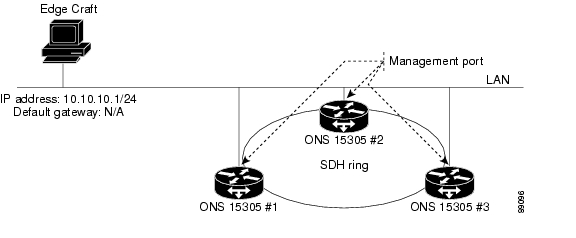
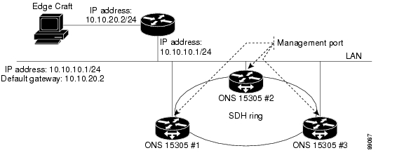
4.2.2 Scenario 1: Cisco Edge Craft and ONS 15305 on the Same Subnet
Figure 4-8 Cisco Edge Craft and ONS 15305 on the Same Subnet
4.2.3 Scenario 2: Cisco Edge Craft and ONS 15305 on Different Subnets
Figure 4-9 Cisco Edge Craft and ONS 15305 on Different Subnets
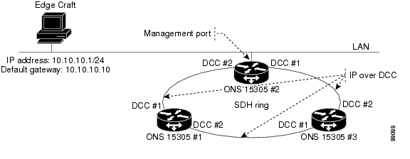
4.2.4 Scenario 3: IP over DCC
Figure 4-10 IP over DCC
4.2.5 Scenario 4: IP over PPP
Figure 4-11 IP over PPP
Thethird-party equipment supports:
•
•
4.3 Manage Common Parameters
The purpose of this section is guide you through management of the attributes that are related to the network element sub-rack and the common hardware and software.
The section includes viewing and modifying NE parameters, time settings, users, available features, and the physical inventory, restart issues, LEDs and alarm output, and ping mechanism.
Synchronization, download of software, upload and download of configuration data, and management of NE's are described in separate sections.
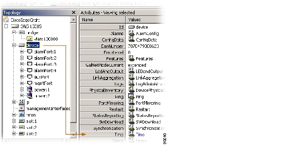
4.3.1 View Common Parameters
Select device in the topology browser.
The common attributes (parameters) as defined in the information model are:
•
•
•
•
•
•
•
•
•
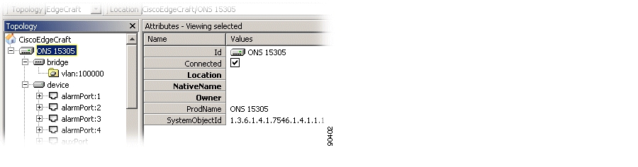
4.3.2 Identify the Network Element
Step 1
Step 2
•
•
•
Figure 4-12 Identification of Network Element
Step 3
4.3.3 Time Settings
The following steps explain how to change time settings for an ONS 15305.
Step 1
Figure 4-13 Time Settings - Time Attribute
Step 2
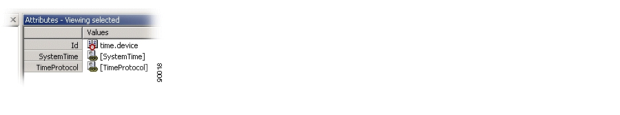
Figure 4-14 Time Attribute - Values
Step 3
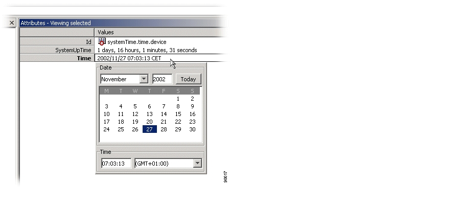
Figure 4-15 Time Attributes - System Time
.
Step 4
•
•
•
4.3.4 Users
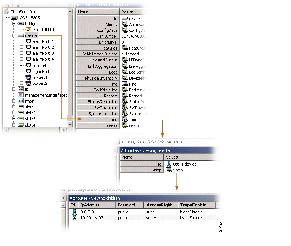
This section explains how to add a new user ( Figure 4-16) and change the VT 100 password.
Figure 4-16 Add a New User - Overview
4.3.4.1 Add a New User
Step 1
Step 2
Step 3
Step 4
Step 5
Step 6
4.3.4.2 VT 100 Password (ONS 15302 only)
Step 1
Step 2
Step 3
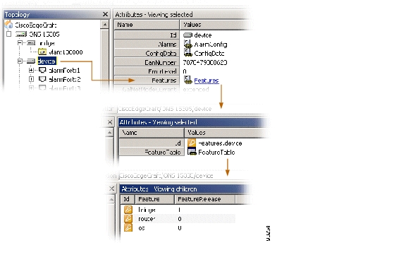
4.3.5 Available Features (Licenses)
In the topology browser select device > Features > FeatureTable to view available licences ( Figure 4-17).
Figure 4-17 Available Features
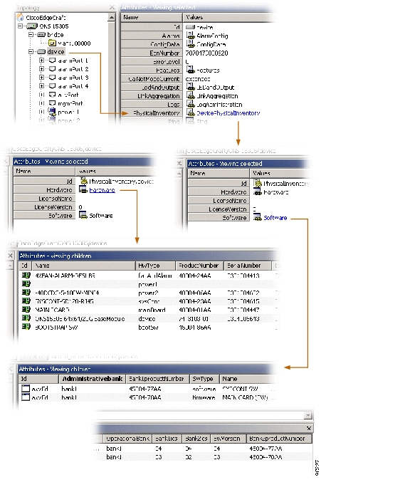
4.3.6 Physical Inventory - ONS 15305
Step 1
Figure 4-18 Physical Inventory - Overview
Step 2
Step 3
4.3.7 Physical Inventory - ONS 15302
In the topology browser select device > inventory.
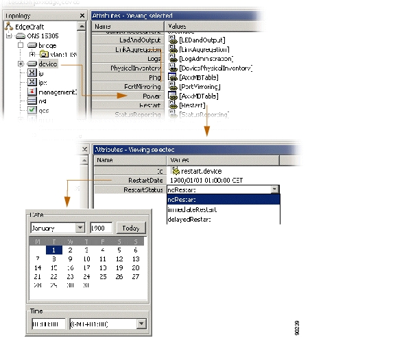
4.3.8 Restart the ONS 15305
Step 1
Figure 4-19 Restart of Network Element - Overview
Step 2
Step 3
Step 4
4.3.9 Restart the ONS 15302
Step 1
Step 2
Step 3
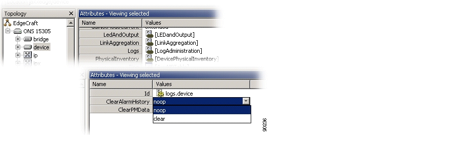
4.3.10 Logs (Alarm Logs, Performance Data Logs)
4.3.10.1 Clear Alarm History
Step 1
Step 2
Step 3
Step 4
4.3.10.2 Clear PM Data
Step 1
Step 2
Step 3
Figure 4-20 Clear Alarm- and Performance Data Log
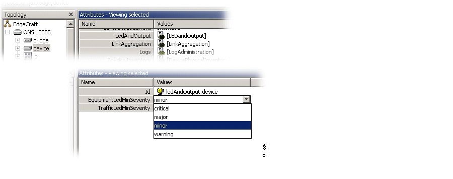
4.3.10.3 LEDs and Alarm Output
Step 1
Step 2
Figure 4-21 LEDs - Severity Selector
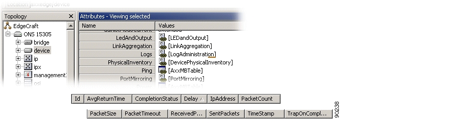
4.3.10.4 Ping Mechanism
Step 1
Step 2
•
•
•
•
•
Figure 4-22 Ping Mechanism
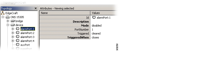
4.3.10.5 Alarm Ports
Step 1
Step 2
•
Free text description.
•
enabled or disabled
•
opens or closes (when an alarm is to be triggered)
Figure 4-23 Alarm Ports
.
Step 3
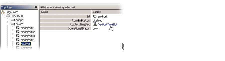
4.3.10.6 AUX Port - ONS 15305
Step 1
Figure 4-24 AUX Port
Step 2
•
•
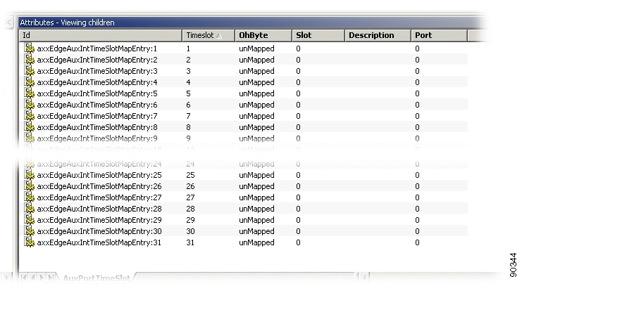
Figure 4-25 AUX port - Timeslots
Step 3
•
•
•
•
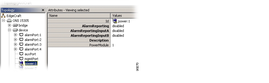
4.3.10.7 Power Module - ONS 15305
Step 1
Figure 4-26 Power Module - Attributes
Step 2
•
disabled or enabled
•
disabled or enabled
•
disabled or enabled
•
free text description
4.4 Synchronization Management
The purpose of this section is to select the synchronization source for internal SDH timing (T0) and external synchronization output (T4).
The ONS 15305 T0 and T4 automatic selection processes can select the source from a short list of available inputs. This selection is based on quality and priority.
You can override the automatic selection process by manual commands.
The first part of this section gives a short introduction to SDH synchronization which is meant to help the reader in understanding the requirements specified in this document.The synchronization is G.781 compliant.
Note
4.4.1 SDH Synchronization
4.4.1.1 Synchronization Networks
A synchronization network is a set of clock nodes that are maintained in synchronization with one another. Synchronization networks require accurate transfer of synchronization reference information between nodes so that their relative synchronization can be monitored and maintained.
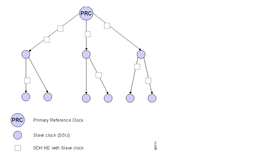
Since it is difficult to synchronize all international nodes from the same master clock, each network operator typically has a primary reference clock (PRC) as defined in ITU-T Recommendation G.811.
From the PRC the synchronization reference information is distributed to all nodes in the SDH network in a tree-type network topology ( Figure 4-27).
Figure 4-27 Synchronization Network Example
Intermediate slave clocks can enter holdover conditions if their connection to the master clock is lost. Slave clocks called Synchronization Supply Units (SSUs) will continue to serve their branch of the network until the connection with the PRC is reestablished. There may be several SSUs concatenated in a large network.
Intermediate SDH NEs will also contain slave clocks, the SDH equipment Clock (SEC). Their quality is not sufficient for providing synchronization reference information to other parts of the network, but they can serve the SDH NE itself in holdover mode if all high-quality incoming references are lost.
As shown in Figure 4-27, the SDH NEs have a dual role since they need a synchronization reference to operate properly in a network and they are important for distribution of synchronization reference information to other networks.
4.4.1.2 Selecting the Best Synchronization Reference
To reinforce the reliability of the synchronization network, alternative routes are often used between the clocks. The slave clock can then be switched to another synchronization reference manually, or automatically by monitoring the signal at the physical interface.
An improvement to simple signal monitoring is to send the synchronization status message (SSM) along with the synchronization signal to indicate the quality level (clock type) of the source clock. The next clock in the chain can now select the best clock based on this quality level.
Not all connections used for synchronization can send the SSM along with its synchronization reference. In this case it is possible to manually indicate the quality level for this interface in ONS 15305. This ensures that also references without SSM can be part of the automatic selection process that is based on quality level.
To avoid timing loops in the network it may be necessary to indicate in SSM that a synchronization reference should not be used. To do so, send the do not use (DNU) message.
4.4.1.3 Synchronizing the SDH Equipment
All SDH equipment contains a clock for the SDH pointer adjustments, cross-connection matrix operations, and the outgoing line signal (STM-N). It is normally operating as a slave clock and locked to a high quality incoming reference, but can run in holdover mode if the reference is lost.
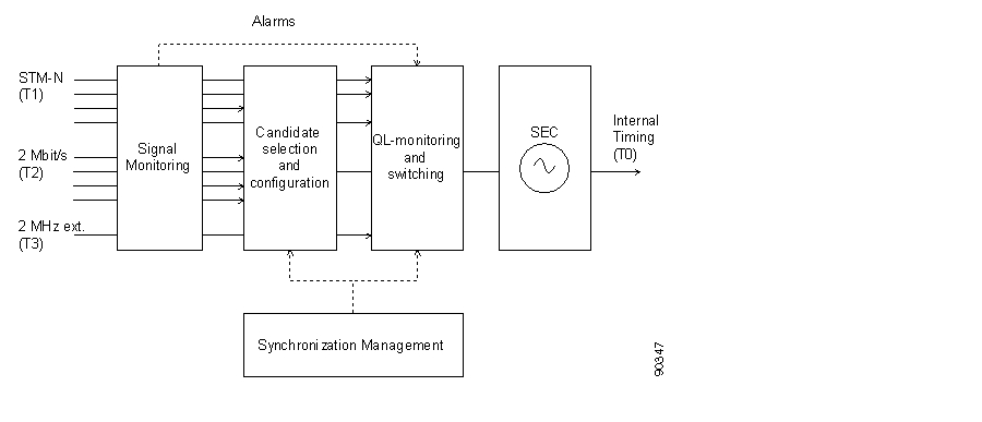
This section describes how the internal timing (T0) is derived from the available synchronization references in ONS 15305.
Synchronization reference information can be extracted from any of the incoming STM-N SDH interfaces (T1), 2 Mbps PDH interfaces (T2), or the external 2 MHz synchronization input (T3) as indicated in Figure 4-28.
The figure shows that only one the available synchronization references will be used as a reference for the SEC. SEC is the clock used for internal timing (T0). When no reference is available it will run in Hold-over mode.
Figure 4-28 T0 Selection
4.4.2 ONS 15305
4.4.2.1 Signal Monitoring
All interfaces are monitored for signal level and framing errors. The failure will be reported to the candidate selection and QL-monitoring and switching processes.
4.4.2.2 Candidate Selection and Configuration
In the ONS 15305 up to five synchronization reference candidates can be selected to participate in the selection process.
For each synchronization source candidate the following parameters can be read or configured:
•
•
•
•
•
•
•
For each synchronization source candidate the following methods are available:
•
•
4.4.2.3 QL-Monitoring and Switching
The QL-monitoring and selection process will continuously monitor the QL of the candidate synchronization references and select the reference with the best QL. Only error free references are included in the selection process. (Alarms are detected in the signal monitoring functional block). If there is more than one candidate with the highest available QL, the priority parameter will be used for selection.
The following parameters can be read or configured for the selection process:
•
•
–
–
–
4.4.2.4 SEC
The ONS 15305 slave clock.
SEC will enter holdover mode for the specified Hold-Off time if an alarm is detected on the selected synchronization reference. After the Hold-Off time the selection process will switch to the error free reference with the highest QL.
When a candidate synchronization reference recovers from an alarm condition, the signal is free for faults for the wait-to-restore period before taken into consideration by the selection process.
The selected T0 reference is also used on all output STM-N signals.
4.4.2.5 Synchronizing External Equipment
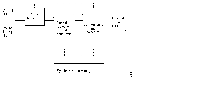
ONS 15305 also provides an external synchronization output (T4). This is a separate 2 MHz signal that can be used directly as a synchronization reference for other equipment or as a synchronization reference to separate stand alone synchronization equipment (SASE).
Synchronization reference information can be extracted from any of the incoming STM-N SDH interfaces (T1) or the internal timing (T0) as indicated in Figure 4-29.
The figure shows that only one of the available synchronization references will be used for external timing (T4).
Figure 4-29 T4 Selection
4.4.2.6 Rules
•
•
•
•
•
•
•
•
•
•
•
•
•
•
•
•
4.4.2.7 Synchronization Alarms
Synchronization alarms are treated the same as other ONS 15305 alarms.
Figure 4-29 identifies the alarms related to SDH synchronization events.
Note
4.4.3 View the Synchronization Data (T0 or T4)
T0 and T4 Synchronization are combined in the flow descriptions because of their common behavior. Users are assumed to be experienced SDH users because synchronization management is not directly related to the services offered by ONS 15305.
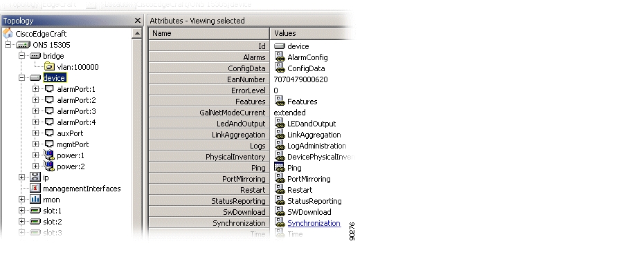
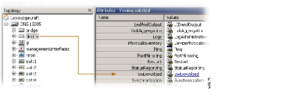
Access the synchronization attributes from the topology browser ( Figure 4-30).
Figure 4-30 Synchronization - Selecting Managed Object
.
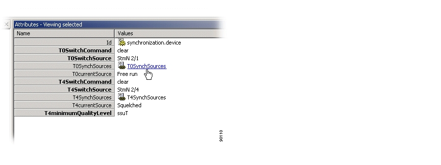
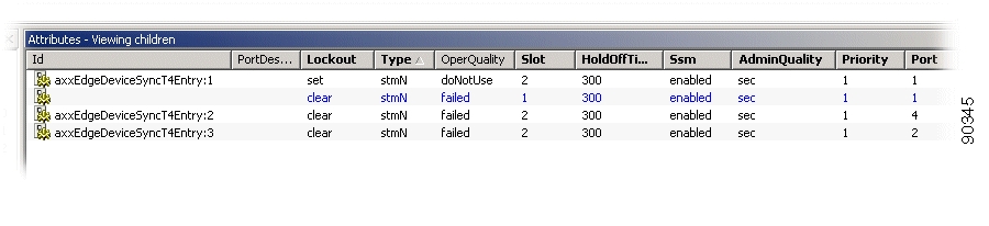
The system presents a list of all Synchronization Source candidates ( Figure 4-31).
Figure 4-31 Synchronization - T0 SynchSources attribute
l.
If the source experiences a signal error the SSM attribute shows failure instead of the SSM value.
The system presents the synchronization attributes with the relevant data.
4.4.4 Add Synchronization Source Candidate (T0 or T4)
Step 1
Step 2
Figure 4-32 Add Synchronization Source
Step 3
–
–
–
–
–
–
–
–
Step 4
If you attempts to add a new synchronization source candidate when the candidate list is fully populated (five entries), you will be informed that a candidate must be deleted before adding a new candidate.
The system verifies that the candidate is legal before performing the addition. If any errors are found, the candidate is not added and you are given the opportunity to correct the problem.
You can add more than one candidate before committing, and a failure on one candidate has no consequence for the addition of the other candidates.
4.4.5 Modify Synchronization Source Candidate (T0 or T4)
Step 1
Step 2
QL can only be modified if SSM enabled is False.
Step 3
4.4.6 Delete Synchronization Source Candidate (T0 or T4)
There are two methods for deleting a synchronization source candidate:
Step 1
Step 2
Step 3
Step 1
Step 2
Step 3
Step 4
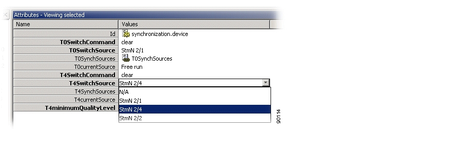
4.4.7 Operate Synchronization Switch (T0 or T4)
Step 1
Figure 4-33 Operate Synchronization Switch 1
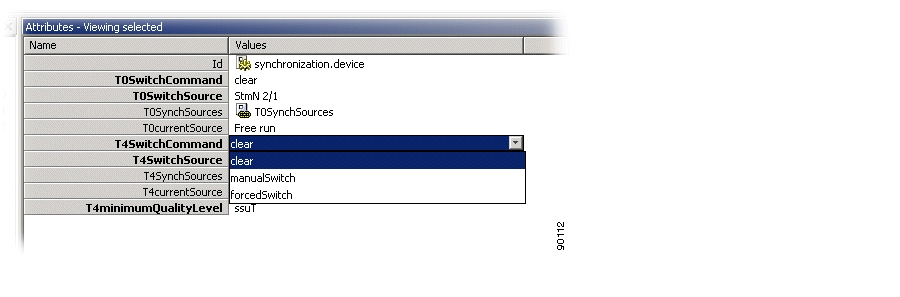
Step 2
Figure 4-34 Operate Synchronization Switch 2
.
Step 3
If the switch parameters are valid, the switch is performed. If a manual or forced switch is performed, the selected source will remain selected until a new forced, manual, or clear command is sent.
4.4.8 View Synchronization Switch (T0 or T4)
Step 1
Figure 4-35 View Synchronization Switch
Step 2
•
•
4.4.9 Activate Synchronization on the ONS 15302
Complete the following steps to activate synchronization for the ONS 15302.
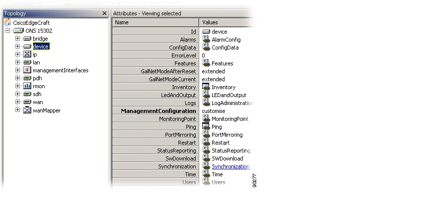
Step 1
Figure 4-36 Select Synchronization
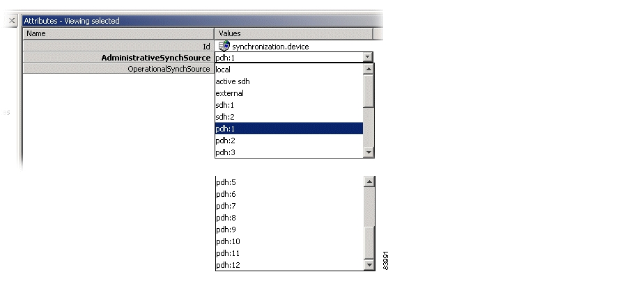
Step 2
Figure 4-37 Select AdministravtiveSynchSource
Step 3
4.5 Download Software to a Network Element
The purpose of this section is to describe the download of new software to the network element. The task of the management system is to give the network element the necessary information for it to begin downloading new software. The download process is controlled by the element itself.
The section involves presentation of an ongoing download process, starting a new software download process, restart of device after download, and switching between two banks in the element where the software is located.
4.5.1 Network Release
The network element contains device software, firmware, and license and module firmware. Software and firmware updates are delivered in network releases, which supports a given set of traffic modules. If a new module is introduced, the network element needs a new network release.
A network release is delivered as a zip-file together with a network release control file. The file must be unzipped and its contents must be copied to the TFTP server. You must initiate the download of the control file. The remaining part of the upgrade will be controlled by the embedded software on the network element; therefore, verify which files are included in the release and download those files that are missing or are too old in the network element.
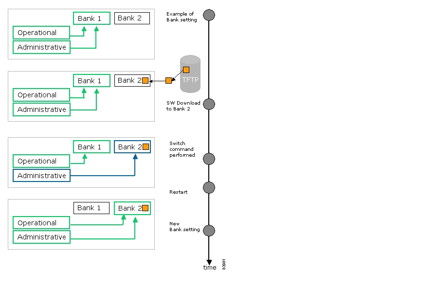
4.5.2 Operational and Administrative Software Bank
ONS 15305 network elements store software or firmware in banks. There are two banks, one administrative and one operational. Bank 1 initially is both the administrative and the operational ( Figure 4-38). After a software download to bank 2, a switch (bank) command is performed and bank 2 becomes the administrative bank. When a restart is done, bank 2 also becomes the operational bank and the new software is active.
Figure 4-38 Example of Switching Software Banks
4.5.3 Effect of Software Upgrades on Traffic
A software update/upgrade including an FPGA fix will affect all traffic. Traffic affected depends on module configuration, therefore a network relase download will affect the modules that are a target for the FPGA fix in the downloaded network release.
It is possible to reset (reboot) the device with or without resetting the current configuration. Reboot have minimal impact on traffic processing. The following situations will affect Ethernet/IP traffic and require a device reset to become operative:
•
•
•
•
The period of time from the moment you have triggered a restart to when the device is up and running depends on modules and the software configuration of the device. The down period depends on installed modules and configuration.
4.5.4 Download an ONS 15305 Network Release
A network release is delivered as a zip-file together with a network release control file ( Figure 4-39).
Note
Step 1
Step 2
Step 3
Step 4
Step 5
Figure 4-39 Download of Release Files
Step 6
Step 7
Step 8
Note
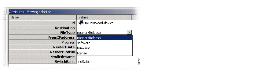
4.5.5 Download Software to the ONS 15305
Step 1
Figure 4-40 Select Device
.
Modify the following attributes as needed:
•
•
•
•
•
•
•
•
–
After the restart the operational bank will be switched and the new (downloaded) SW will be active.
–
The operational bank will not be switched after the restart, hence a manual switch must be performed in order to activate the new software. For further details see "Switch Banks Manually" section.
Step 2
4.5.5.1 Switch Banks Manually
Step 1
Step 2
Step 3
Step 4
4.5.6 Download Software to the ONS 15302
Step 1
Step 2
Step 3
Step 4
Step 5
4.6 Back Up and Restore Configuration Data
The purpose of this section is to guide you through management of the configuration data in the network element.
The configuration data is BER coded and cannot be edited on the host.
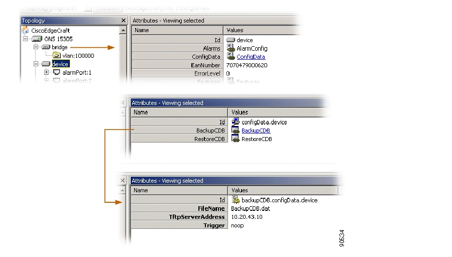
4.6.1 Back Up Configuration Data
Use the following steps to perform a back up of the configuration data and put it on the TFTP-server.
Step 1
Step 2
Figure 4-41 Select ConfigData
.
Step 3
Step 4
•
Destination IP address if configuration data should be uploaded on a remote host.
•
File name and path for the configuration data storage.
•
If set to noop only parameters are saved.
If set to backup, the backup operation is started when clicking save.
Step 5
Step 6
Step 7
Note
Note
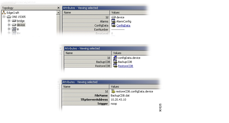
4.6.2 Restore Configuration Data
If a scheduled restart is set before a new configuration data download process is started, the scheduling parameters will be overwritten.
For Cisco Edge Craft to restart the NE after the TFTP download session is terminated, the Cisco Edge Craft needs to be able to capture the endTftpSession trap sent from the NE. To enable trap-sending see the "1.3.2 Configure Community-Handler" section on page 1-5.
Step 1
Step 2
Figure 4-42 Select Device
Step 3
Step 4
•
Source IP address if configuration data to be downloaded.
•
File name and path for the configuration data storage.
•
If set to noop only parameters are saved.
If set to backup, the restore operation is started when clicking save.
Step 5
Step 6
The TFTP upload process begins and the configuration data is stored in the network element. Cisco Edge Craft will restart the network element after the restore is complete.
Note
4.7 Alarm and Event Configuration
This section explains how to configure alarm and event reporting and suppress and configure specific alarms.
The network element has a predefined set of combinations of managed objects and alarm types, that means alarm points. These combinations can not be changed by you but the severity level and a description can be defined.
Suppression of specific alarms is important to avoid alarm floods in the network and to focus on the root cause. The ONS 15305 allows you to suppress many alarm types, for example AIS.
You can suppress alarms that are oscillating between activity and inactivity. A time interval (a persistency filter) indicates the time period an alarm must have been on or off before being reported. The persistency filters are defined for a group of alarms of a specific type.
There are three possible persistency group categories:
•
•
•
For some managed objects you can enable or disable the alarm reporting.
4.7.1 Event Forwarding
Alarms or events cannot be reported before the identity of the receiver of alarms and events has been configured. It is possible to forward alarms and events to more than one receiver.
Event forwarding is enabled when a new user is added with the TrapsEnable attribute set to TrapsEnable as described in the "5.3.2 Set a Loop in a ONS 15305 PDH Port" section on page 5-8.
4.7.2 Configure General Alarm Reporting
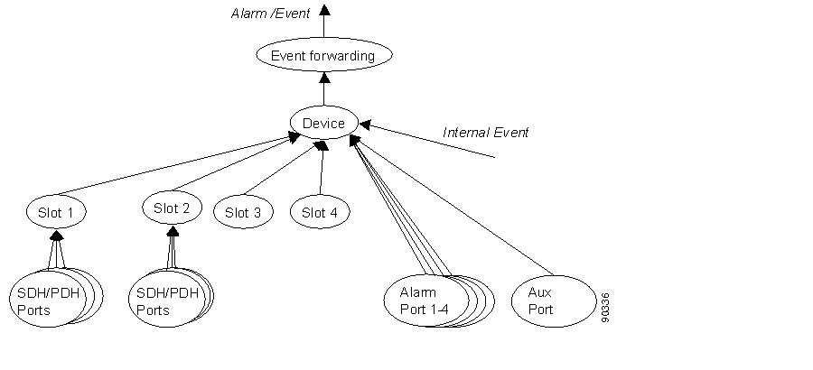
In ONS 15305 there are several levels where alarm reporting can be disabled or enabled. Alarms will be reported to a manager only when alarm reporting is enabled on all levels ( Figure 4-43). In addition the event forwarding must be configured for the IP address of the manager (described in the "Event Forwarding" section).
Figure 4-43 General Alarm Reporting Filters.
Note that all alarms from objects in the following sections must pass through the filter:
In addition to general alarm reporting, it is possible to filter specific alarm types on specific object instances.
4.7.2.1 Device Alarm Enabling
It is possible to enable or disable alarm and event reporting from ONS 15305. In the disabled state, alarms or events are not reported (some generic events, like cold start, etc. are still reported).
Step 1
Step 2
4.7.2.2 Slot Alarm Enabling
Step 1
Step 2
4.7.2.3 Traffic Port Alarm Enabling
Step 1
Step 2
4.7.2.4 Alarm Port Alarm Enabling
Step 1
Step 2
4.7.2.5 Aux Port Alarm Enabling
Step 1
Step 2
Note
4.7.3 Suppress Specific Alarms
In addition to configuration of the general alarm filters described above, it is possible to suppress specific alarm types to avoid alarm floods in the network. Other alarms from the same objects will be reported independently of these settings.
4.7.3.1 Suppress RDI, EXC, DEG, SSF Alarms
RDI, EXC, DEG, and SSF alarm reporting can be suppressed from the VC-12, VC-3 or VC-4 layers.
Step 1
Step 2
•
•
•
•
4.7.3.2 Suppress AIS Alarms from SDH Ports
AIS alarm reporting can be suppressed from the TU-12, TU-3, or AU-4 layers.
Step 1
Step 2
4.7.3.3 Suppress AIS Alarms from E1 Ports
Step 1
Step 2
4.7.3.4 Suppress AIS Alarms from AUX Port
Step 1
Step 2
4.7.4 Modify Alarm Severity and Description
It is possible to modify the severity of the reported alarms from ONS 15305.
Step 1
Step 2
4.7.5 Set Signal Degrade Threshold
The threshold for a DEG alarm to be reported (and used for MSP switching) can be set for the VC-12, VC-3, VC-4, MS, and RS layers.
Step 1
Step 2
4.7.6 Modify Alarm Persistency
Alarm reporting on and off can be delayed by setting the alarm persistency filters in ONS 15305. The alarms are divided into groups according to their importance for fault management ( Table 4-7, Table 4-8, and Table 4-9).
4.7.6.1 Persistency Group 1 (HighOrderLevel)
4.7.6.2 Persistency Group 2 (Unfiltered)
Table 4-8 Persistency Group 2 (Unfiltered)
LOP
tu4, tu3, tu12
LOM
vc4
LOF-RX, LOF-TX
e1
4.7.6.3 Persistency Group 3 (LowOrderLevel)
Step 1
Step 2
4.7.7 Modify ONS 15302 Alarm Configuration Attributes
Step 1
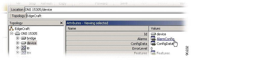
Figure 4-44 Select Device
Step 2
Figure 4-45 Select Alarm Config
Step 3
Step 4
4.7.7.1 View all Alarm Reporting Instances
To view all alarm reporting instances, select AlarmReportingAll ( Figure 4-46).
Figure 4-46 Select AlarmReportingAll
4.7.7.2 Enable Alarm Reporting
Step 1
Figure 4-47 Select AlarmReporting
Step 2
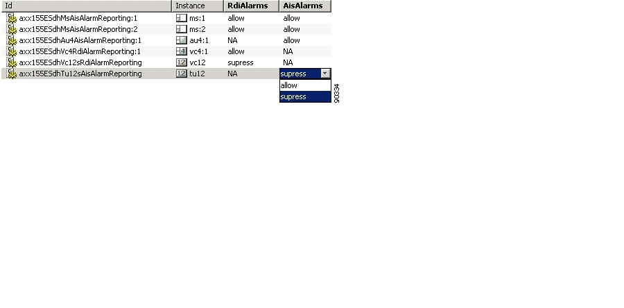
4.7.7.3 Modify Ais Rdi Alarm Reporting
Step 1
Figure 4-48 Select AlarmreportingAisRdi
Step 2
Step 3
Figure 4-49 Select AIS Attributes
Step 4
Step 5
4.7.7.4 Modify Alarm Persistency
Modifying the alarm prsistency filters in the ONS 15302 can prevent alarms that vascillate between activity and inactivity.
Step 1
Figure 4-50 Set Alarm Persistency Attributes
Step 2
Step 3
4.7.7.5 Modify Signal Degraded (Sd) Threshold
Step 1
Figure 4-51 Select SDTreshold
Step 2
Step 3
Figure 4-52 Set SDTreshold
.
Step 4
4.8 Manage ONS 15305 Slots
A slot represents a physical position on the network element where different hardware modules can be installed ( Figure 4-53). This section explains how to install and remove modules.
Figure 4-53 ONS 15305 Slots
4.8.1 View a Slot
The browser presents four slots numbered from 1 to 4. The slot attributes as defined in the information model are available in the attribute window. Each slot can be equipped with one HW module. By default the slot is unequipped ( Figure 4-54).
Figure 4-54 Select Slot
A slot can be empty or have a hardware module with a given number of ports and software version installed ( Figure 4-55).
Figure 4-55 Slot Module - Port Concept
The physical inventory data for an installed module also appears in the attribute window.
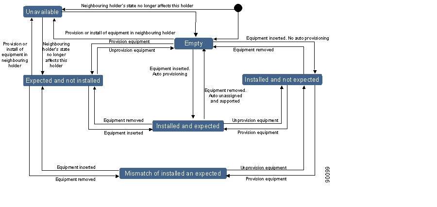
You can preconfigure a slot with an expected module before physically installing a module. The system populates the topology browser according to the specified expected module. The slot has an attribute that reflects the relation between the expected module and the installed module. Slot states include:
•
•
•
•
•
•
•
A state diagram for the possible transitions of a slot is shown in Figure 4-56. This is the suggested state machine from TMF 814 supporting documentation, equipmentStates.pdf.
Figure 4-56 Relation Between Installed and Expected Module in a Slot.
A state machine for the values of the attribute describing the relation between an installed and expected module is shown in Figure 4-56.
If a mismatch between the two modules occurs, an alarm will be generated. The alarm is cleared if the module is replaced or the expected module is changed, which means a match between expected and installed is present.
Before replacing a module and selecting a new expected module type, the expected module of the slot must be set to unequipped.
For management of different ports, see Chapter 5, "Traffic Port Management."
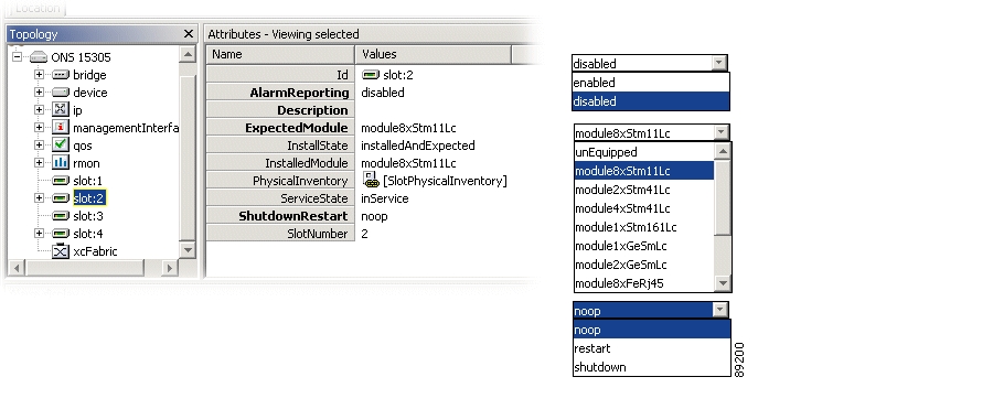
4.8.2 Modify a Slot
To modify the expected module attribute, the ports of the previous expected module must be unused and unstructured.
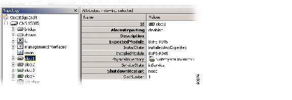
Step 1
Figure 4-57 Select Target Slot
Step 2
•
enable or disable
•
select module of current interest
•
noop, restart or shutdown. (noop; No operation is applied)
Note
Step 3
Some changes require a restart of the module. If this is the case you will be prompted to restart.
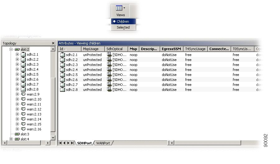
When a slot has been configured to contain a specific module, the ports of the module are automatically created in the network element. The type of ports created depends on the module type configured for the slot ( Figure 4-58).
Figure 4-58 Set View Mode to Children
.
The ports of an installed module were not created if the slot was configured to contain another module type or being empty.
![]()
![]()
![]()
![]()
![]()
![]()
![]()
![]()
Posted: Fri Sep 14 11:44:20 PDT 2007
All contents are Copyright © 1992--2007 Cisco Systems, Inc. All rights reserved.
Important Notices and Privacy Statement.