|
|

Table Of Contents
5.2.1 Configure ONS 15305 SDH Port Structure (Channelization)
5.2.2 Modifyor Remove ONS 15305 SDH Port Structure
5.2.3 Set and Read Path Trace Identifiers
5.2.4 Monitor SDH Port Performance
5.2.5 Enable the SDH Port to Carry Traffic and Report Alarms
5.2.6 Set ONS 15305 SDH Port Synchronization Quality Output Signaling
5.2.7 SDH Port as a Synchronization Source Input
5.2.8 DCC Channels on the SDH Port Carrying Management Traffic
5.3.1 Set the Port Mode for ONS 15305
5.3.2 Set a Loop in a ONS 15305 PDH Port
5.3.3 Set a Loop in a ONS 15302 PDH Port
5.3.4 Release a Loop in a PDH Port
5.3.5 Assign VC12s in the ONS 15302
5.3.6 Set and Read Path Trace Identifiers
5.3.7 Monitor PDH Port Performance
5.3.8 Enable the PDH Port to Carry Traffic and Report Alarms
5.3.9 Cross-Connect the ONS 15305 PDH Port to Another Port
5.4.1 ONS 15305 - LAN Port Attributes
5.4.2 ONS 15302 LAN Port Attributes
5.5.2 Add Initial WAN Port Capacity
5.5.3 Modify WAN Port Capacity
5.5.5 Modify Protection Parameters on the WAN Port
5.5.6 Command a WAN Port Protection Switch
5.5.7 Set Path Trace Identifiers for a WAN Port
5.5.8 Read Path Trace Identifiers for a WAN Port
5.5.9 Monitor WAN Port Performance
5.5.10 Advanced WAN Port Operations
5.6.1 WAN ports and the Mapping
5.6.2 Differences Between the ONS 15305 and ONS 15302
5.6.3 Add Initial WAN Port Capacity
5.6.4 Increase Capacity in the SDH Server Layer
5.6.5 Decrease Capacity in the SDH Server Layer
5.6.6 Set Path Trace Identifiers for a WAN Port
5.6.7 Read Path Trace Identifiers for a WAN Port
5.6.8 Monitor WAN Port Performance
5.6.9 Advanced WAN Port Operations
5.7 ONS 15305 SDH Layer Network and Cross-Connections
5.7.2 Open the Cross-Connection GUI
5.7.3 Browse Existing Cross-Connections
5.7.4 Set Up Cross-Connections from a 2 Mbps E1 Port to a Timeslot in an SDH Port
5.7.5 Set Up Cross-Connections from a 45 Mbps E3 (T3) Port to a Timeslot in an SDH Port
5.7.6 Create a Pass-through Cross-Connection
5.7.7 Modify Cross Connections
5.7.8 Protect Cross Connections
5.7.9 Delete Cross-Connections
5.7.10 Advanced Cross-Connection Operations
5.8 ONS 15305 SDH Protection Management
5.8.1 Multiplex Section Protection
5.8.6 Legal Combinations of SNCP and MSP
5.8.7 SubNetwork Connection Protection
5.9 ONS 15302 SDH Protection Management
Traffic Port Management
The ONS 15305 can be equipped with a number of different port types. Some ports are part of the base unit and always present (management port, AUX ports, alarm input, and output ports). The alarm ports and auxiliary port cannot be created or deleted.
For more information see the "4.1.1 Management Port Configuration" section on page 4-2, the "4.3.10.5 Alarm Ports" section on page 4-20, and the "4.3.10.6 AUX Port - ONS 15305" section on page 4-20.
Traffic ports are available on replacable traffic modules. When a slot is configured to support a specific traffic module, the ports of the traffic module are automatically created as described in the "4.8 Manage ONS 15305 Slots" section on page 4-46.
This chapter explains how to configure SDH, PDH, LAN, and WAN traffic ports.
5.1 Select a Traffic Port
Traffic ports are always located on a traffic module in Slots 1 to 4. This section describes how to select a traffic port independent of the traffic it carries.
Step 1
Click on the ONS 15305 managed object, then in the topology browser click the slot managed object where the port is located.
Step 2
The port is selected and the attributes related to the physical and electrical characteristics of the port appear in the attributes view.
The physical port usually carries a set of protocols (for example SDH) and the protocols are available from the topology browser.
5.2 SDH Ports
Note
5.2.1 Configure ONS 15305 SDH Port Structure (Channelization)
By default the SDH ports are unstructured (or not channeled) when created. Only the sdh Port, rs, ms and aug1 managed objects are available. In this state the paths inside the STM-N frame cannot be terminated or cross connected, but the port can be used as a protection port in an MSP protection scheme and a synchronization source candidate. It can also carry DCN traffic in the DCC channels.
The motivation for structuring an SDH port is to identify the paths in the STM-N frame and make them available for cross-connection. As you structure the port it will fan out in the topology browser, showing termination points that are now available for cross-connection.
5.2.1.1 AU4 Termination Points for Cross-connection
Step 1
Step 2
Step 3
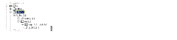
Figure 5-1 Select the Aug1 Managed Object
Step 4
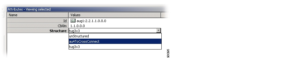
Figure 5-2 Set the Structure Attribute
Step 5
Step 6
5.2.1.2 Tu3 Termination Points for XC
Step 1
Step 2
Step 3
Step 4
Step 5
Step 6
5.2.1.3 Tu12 Managed Objects for XC
Step 1
Step 2
Step 3
Step 4
5.2.2 Modifyor Remove ONS 15305 SDH Port Structure
It is also possible to modify or remove the structure of an SDH port when the involved termination points are not cross connected.
5.2.2.1 Modify Between Tu12 and Tu3 Objects
Step 1
Step 2
5.2.2.2 Modify Between Au4 and Tu3 or Tu12 Objects
Step 1
Step 2
Step 3
Note
Note
5.2.3 Set and Read Path Trace Identifiers
Path Trace is available at two levels in an SDH port:
•
•
5.2.3.1 Set or Read RS Path Trace Identifiers
Step 1
Step 2
Step 3
Step 4
•
Set to enable if TIM alarms should be reported when there is a mismatch between PathTraceReceived and PathTraceExpected.
•
Enter a value for the path trace identifier that you expect to receive from the other side of the path.
•
Enter a value for the path trace identifier that you want to transmit to the other side of the path.
Step 5
•
The actual received path trace identifier from the other side of the link.
Step 6
5.2.3.2 Set or Read VC-4 Path Trace Identifiers
Note
Step 1
Step 2
Step 3
Step 4
Step 5
The attributes are the same as the RS path trace.
Step 6
Note
5.2.4 Monitor SDH Port Performance
Performance monitoring is available at three levels in the SDH port:
•
•
•
5.2.4.1 Read RS PM Counters
Step 1
Step 2
Step 3
Step 4
The following attributes are available:
•
•
Step 5
The following attributes are available:
•
•
5.2.4.2 Read MS PM Counters
Step 1
Step 2
Step 3
The attributes are the same as for RS PM.
5.2.4.3 Read VC-4 PM Counters
Step 1
Step 2
Step 3
Step 4
Step 5
The attributes are the same as RS PM in the "Read RS PM Counters" section.
5.2.5 Enable the SDH Port to Carry Traffic and Report Alarms
By default the Administrative Status of the SDH port is set to disabled when the port is created. No alarms are reported before it is enabled.
Step 1
Step 2
Step 3
Note
- No alarms are reported towards the port.
- PM counters for the port will only count 0.
- If the port is part of MSP , the port will not be selected for traffic (unless this is a working port and the protecting port also is disabled or has SPI/RS/MS alarm).
Note
5.2.6 Set ONS 15305 SDH Port Synchronization Quality Output Signaling
STM-N signals are often used to carry synchronization information. A dedicated protocol is used to indicate the quality of the signal from one SDH node to the next SDH node.
Step 1
Step 2
Step 3
Note
5.2.7 SDH Port as a Synchronization Source Input
See the "4.4.4 Add Synchronization Source Candidate (T0 or T4)" section on page 4-28.
5.2.8 DCC Channels on the SDH Port Carrying Management Traffic
See the "4.1.2 DCC Configuration" section on page 4-4.
5.3 PDH Ports
The ONS 15305 can be equipped with two different PDH port types:
•
•
The ONS 15302 is equipped with E1 ports.
5.3.1 Set the Port Mode for ONS 15305
Step 1
Step 2
Step 3
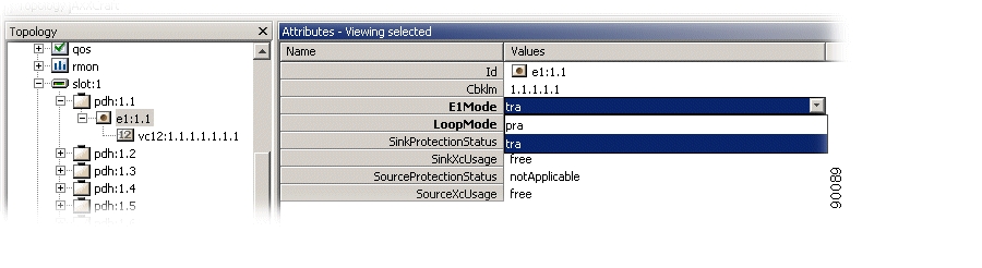
Figure 5-3 Set the E1 Mode Attribute
.
Step 4
Step 5
5.3.2 Set a Loop in a ONS 15305 PDH Port
Step 1
Step 2
Step 3
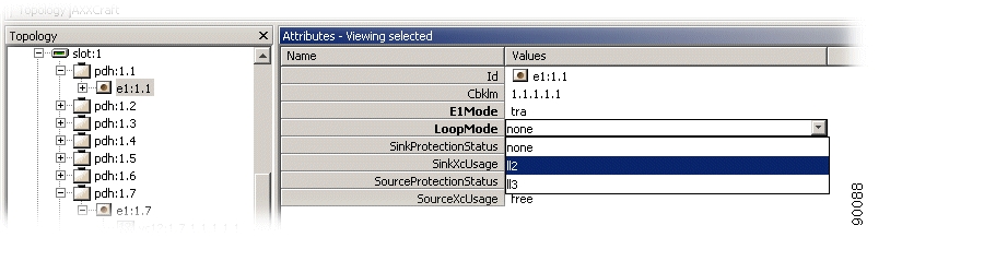
Figure 5-4 Set Loop Mode Attributes
.
Step 4
Note
5.3.3 Set a Loop in a ONS 15302 PDH Port
Step 1
Step 2
Step 3
Step 4
5.3.4 Release a Loop in a PDH Port
Step 1
Step 2
Step 3
Step 4
Note
5.3.5 Assign VC12s in the ONS 15302
Step 1
Step 2
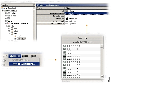
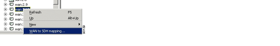
You may use the WAN to SDH mapping window to view available VC12s with cbklm values.
Step 3
Figure 5-5 Assign VC 12 Port
5.3.6 Set and Read Path Trace Identifiers
Step 1
Step 2
Step 3
Step 4
The following attributes can be set:
•
Set to enable if TIM alarms should be reported when there is a mismatch between PathTraceReceived and PathTraceExpected.
•
Enter a value for the path trace identifier that you expect to receive from the other side of the path.
•
Enter a value for the path trace identifier that you want to transmit to the other side of the path.
Step 5
Step 6
Note
5.3.7 Monitor PDH Port Performance
Step 1
Step 2
Step 3
Step 4
The following attributes are available:
•
•
Step 5
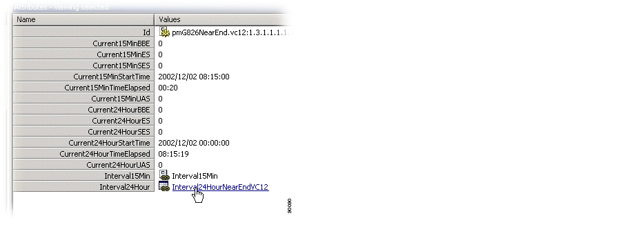
The following attributes are available
•
•
Figure 5-6 Select Interval24Hour
Figure 5-7 Set Interval24Hour Attributes
5.3.8 Enable the PDH Port to Carry Traffic and Report Alarms
By default the administrative status of the PDH port is set to disabled when the port is created. No traffic will pass through the port and no alarms are reported before it is enabled.
Step 1
Step 2
Step 3
Note
5.3.9 Cross-Connect the ONS 15305 PDH Port to Another Port
See "ONS 15305 SDH Layer Network and Cross-Connections" section.
5.4 LAN Ports
5.4.1 ONS 15305 - LAN Port Attributes
An ONS 15305 slot can be configured to carry an 8xFeRj45 module. See the "4.8 Manage ONS 15305 Slots" section on page 4-46 for details.
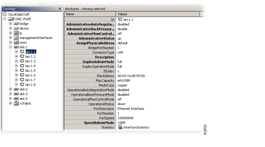
Step 1
Attributes marked as bold are modifiable.
Figure 5-8 LAN Port Attributes
Step 2
•
disabled or enabled
•
disabled or enabled
•
on, off or auto negotiation
•
up, down or testing
•
reserve or default
•
string
•
none, half or full
•
not set, 10M, 100M or 1000M
Step 3
5.4.2 ONS 15302 LAN Port Attributes
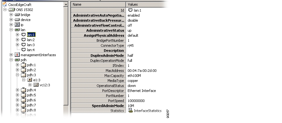
The ONS 15302 is equipped with 4 LAN ports ( Figure 5-9). For configuration of LAN ports see the "ONS 15305 - LAN Port Attributes" section.
Figure 5-9 LAN Port Attributes - ONS 15302
5.5 WAN Ports - ONS 15305
The ONS 15305 can concentrate IP traffic over the SDH network. The purpose of this section is to describe the tasks involved in assigning capacity from the SDH server layer to WAN ports. The total assigned WAN capacity is made up of SDH channels.
Each SDH channel is equivalent to a VC-12 (2 Mbps). This is available in the first release of the network element. Future releases will also include mapping to VC-3 and VC-4. This section only describes the VC-12/TU-12 layer rate.
The SDH channels can be from different SDH ports.
The WAN channels can be sub-network connection (SNC) protected. In the first release of the ONS 15305, only protection scheme SNC/I (inherent monitoring) is supported.
5.5.1 WAN Ports and Mapping
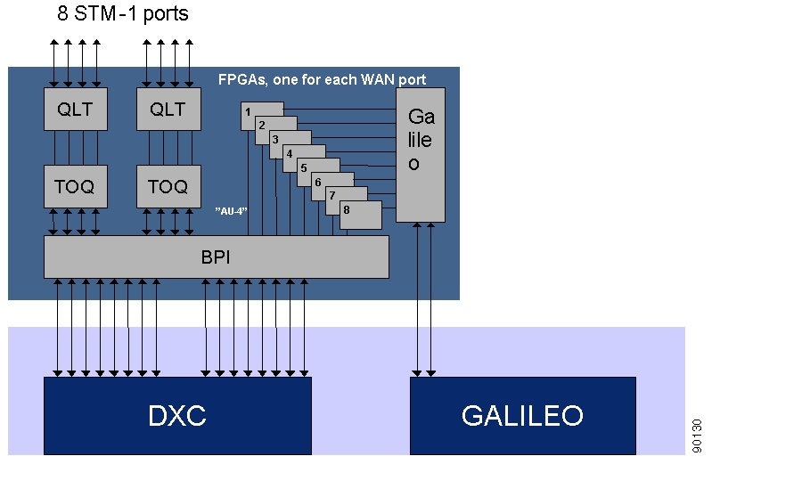
The eight WAN ports are located on the 8xSTM-1 module. They are connected to a Galileo switch ( Figure 5-10). A WAN port has a maximum capacity of 100 Mbps.
Figure 5-10 The 8 x STM-1 Module with WAN Ports
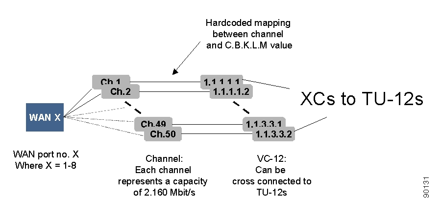
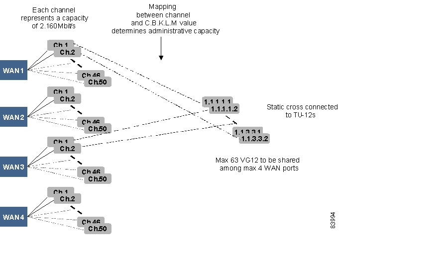
Figure 5-11 shows that the potential capacity of 100 Mbps is realized through 50 channels, each of which can carry 2.160 Mbps. The capacity of the WAN port is therefore decided by how many channels are used for traffic.
A WAN port can be mapped to one STM-1 port, which means there are potentially 63 available VC-12s. Only the first 50 of these are used. These 50 channels have hard-coded mapping to 50 VC-12 containers.
The C.B.K.L.M numbering is described in the "C.B.K.L.M Value Usage" section.
Figure 5-11 View of one WAN Port and its Logical View
The WAN VC-12s are cross connected to the available TU-12s on the SDH ports. All 50 WAN VC-12s are available for cross connection. A WAN VC-12 represents the termination point A in a cross connection and the connection is always bidirectional. The cross connection can be protected.
If there exists a VC-12 (or channel) inside the WAN capacity that is not cross connected, the network element issues an unequipped alarm on the WAN VC-12.
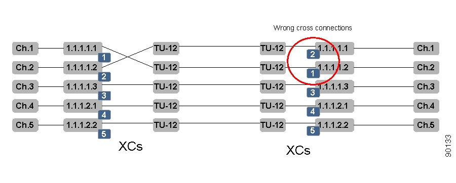
The order of the channels is essential and must be the same on both sides of a WAN connection, for example, containers sent from channel 1 must be received on channel 1. A sequence number is used to indicate the correct order of the VC-12 on the receiving side of a WAN connection between two ONS 15305 network elements. If the connection is not between two ONS 15305 NEs, the sequence number will be zero. Figure 5-12 shows a scenariowhere the cross connection between two TU-12s and two VC-12s in one ONS 15305 are incorrect.
Figure 5-12 Sequence Numbers for Correct Order of TU-12 to VC-12 Cross Connects.
Alarm and performance monitoring data is collected and reported for those VC-12s that are within the WAN capacity.
5.5.2 Add Initial WAN Port Capacity
The addition of WAN port capacity is performed in a two step process.
The first step is to set the administrative capacity of the WAN port. This will tell ONS 15305 how many of the 50 possible WAN channels to use for mapping into the SDH server layer.
Step 1
Step 2
Figure 5-13 Set Bandwidth
.
Step 3
Step 4
The next step is to cross-connect the WAN channels that are in use after setting the administrative capacity.
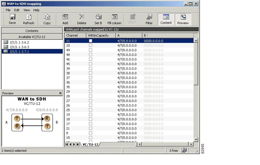
Step 5
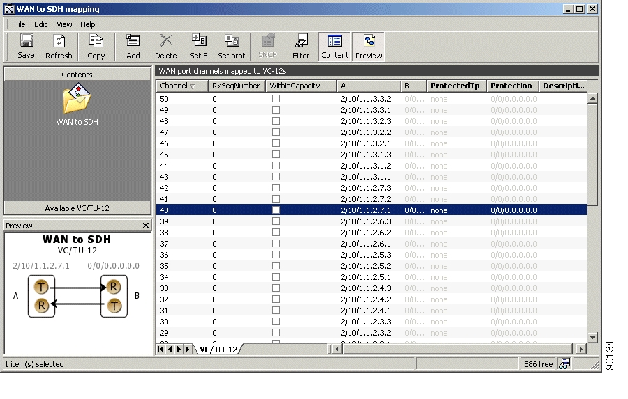
Figure 5-14 Select WAN Port Attributes
A list of all the WAN channels of the WAN port is shown. The list shows the static relation between each channel number and a VC12 object in the WAN port. The WithinCapacity attribute indicates if the channel is in use by the WAN channel (that means if it was included when setting administrative capacity above).
Figure 5-15 Set WAN Port Attributes
.
Step 6
If it is not available select the Content button in the toolbar.
Step 7
Figure 5-16 Select Available VC/TU12
Note
Step 8
Step 9
Step 10
Step 11
Note
Note
5.5.3 Modify WAN Port Capacity
You can modify the WAN port capacity in the same way you added the initial WAN capacity; see the "Add Initial WAN Port Capacity" section.
Step 1
Step 2
Step 3
Step 4
Step 5
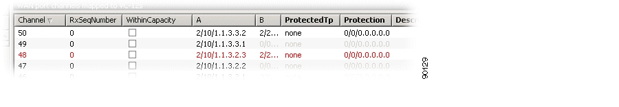
A list of all the WAN channels of the WAN port appears. The list shows the static relation between each channel number and a VC12 object in the WAN port. The WithinCapacity attribute indicates if the channel is in use by the WAN channel (that means if it was included when setting administrative capacity above).
Step 6
Step 7
5.5.3.1 Increase Capacity in the SDH Server Layer
Make sure the content panel is available in the left part of the window. If it is not available select the content button in the toolbar.
Step 1
Note
Step 2
Step 3
Step 4
Step 5
Step 6
5.5.3.2 Decrease Capacity in the SDH Server Layer
Step 1
Step 2
Figure 5-17 Select WAN Channels
.
Step 3
Step 4
Note
5.5.4 Protect a WAN Port
WAN ports can be protected by the SNC protection scheme in the VC12 or TU12 SDH layer, meaning that the WAN channels (not necessarily all WAN channels of a WAN port) can have two different routes through the SDH server network and that the receiving WAN channel selects the route with the best signal.
Step 1
Step 2
Figure 5-18 Select Protected Mode
Step 3
Step 4
Step 5
Note
Step 6
Step 7
Step 8
Step 9
Note
Step 10
Step 11
Step 12
Figure 5-19 Set SNCP Properties Enabled
.
Step 13
Note
5.5.5 Modify Protection Parameters on the WAN Port
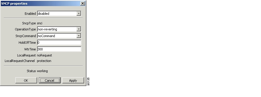
WAN ports are protected as described in the "Protect a WAN Port" section. The SNC is then set up with default parameters. The parameters can easily be modified ( Figure 5-20).
Step 1
Step 2
Step 3
Step 4
Step 5
Figure 5-20 Set SNCP Properties Protection
.
Step 6
5.5.6 Command a WAN Port Protection Switch
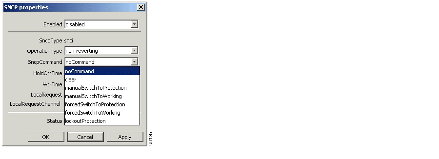
The Cisco Edge Craft user can control the SNC protection switch by sending a command ( Figure 5-21).
Step 1
Step 2
Step 3
Step 4
Step 5
Figure 5-21 Set SNCP Properties Command
.
Step 6
5.5.7 Set Path Trace Identifiers for a WAN Port
Path Trace parameters can be set for each channel (VC12) in the WAN port.
Step 1
Step 2
Step 3
•
Set to enable if TIM alarms should be reported for the WAN port when there is a mismatch between PathTraceReceived and PathTraceExpected.
•
Enter a value for the path trace identifier that you expect to receive from the other side of the WAN channels.
•
Enter a value for the path trace identifier that you want to transmit to the other side of the WAN channels.
Step 4
Note
5.5.8 Read Path Trace Identifiers for a WAN Port
Path trace parameters can be read for each channel (VC12) in the WAN port.
Step 1
Step 2
Step 3
The following attributes can be read:
•
Set to enable if TIM alarms should be reported when there is a mismatch between PathTraceReceived and PathTraceExpected.
•
Enter a value for the path trace identifier that you expect to receive from the other side of the path.
•
Enter a value for the path trace identifier that you want to transmit to the other side of the path.
•
The actual received path trace identifier from the other side of the link.
Note
5.5.9 Monitor WAN Port Performance
Step 1
Step 2
Step 3
The following attributes are available:
•
•
Step 4
The following attributes are available:
•
•
5.5.10 Advanced WAN Port Operations
For frequent users of Cisco Edge Craft, it is possible to make use of the enhanced editing facilities to speed up the configuration work.
5.5.10.1 Select and Insert Multiple Termination Points
Step 1
Step 2
Step 3
Step 4
Step 5
Step 6
Note
If you want to modify the B termination point the relation with the existing B termination point must first be deleted. Then a new termination point can be added.
If you want to modify the protection termination point the ProtectedTP must first be saved as none. Then the protection TP can be modified. Remember to set the ProtectedTP back to a.
Note
5.5.10.2 Manually Enter Termination Points
Step 1
Step 2
Step 3
Step 4
Step 5
Step 6
Step 7
Note
5.6 WAN Ports - ONS 15302
The ONS 15302 can concentrate IP traffic over the SDH network. This section describes the tasks involved in assigning capacity from the SDH server layer to WAN ports.
Each SDH channel is equivalent to a VC-12 (2.160 Mbps). The ONS 15302 has one or four WAN ports depending on the hardware configuration.
5.6.1 WAN ports and the Mapping
The network element has one or four WAN ports. A WAN port has a maximum capacity of 100 Mbps.
The WAN ports are logical ports and not physical ports. The potential capacity of 100 Mbps is realized and guaranteed through 47-50 VC12s, each of which can carry 2.160 Mbps. The overhead (extra bits) are used to handle escaped characters. The capacity of the WAN port is therefore decided by how many VC12s that are assigned to the port.
The ONS 15302 has one STM-1 port and potentially 63 VC12s are available for a WAN port. Each WAN port has 50 channels that are dynamically mapped to VC12s.
The VC-12s have static cross connections to the available TU-12s on the SDH ports.
The order of the 0-50 channels are essential and must be the same on both sides of a WAN connection, for example containers sent from channel 1 must be received on channel 1 ( Figure 5-22).
Figure 5-22 View of the WAN Ports and their Logical View
Alarm and performance monitoring data is collected and reported for the VC-12s.
5.6.2 Differences Between the ONS 15305 and ONS 15302
In ONS 15305 each WAN port has always a potential capacity of 100 Mbps realized through 50 channels. The available capacity is not dependent on the capacity used by the other WAN ports. When you set the capacity, the system selects the first X channels corresponding to this capacity. The channels have a static mapping to VC-12s. You must cross connect the VC-12s to TU-12s to activate the capacity.
In the ONS 15302 each WAN port also has a potential capacity of 100 Mbps, but the available capacity is dependent on the capacity used by the other WAN ports. You set and activate the capacity indirectly by selecting a set of channels and map them to VC-12s. The VC-12s are statically cross connected to TU-12s.
5.6.3 Add Initial WAN Port Capacity
The addition of WAN port capacity is performed in a two-step process.
5.6.3.1 Set the Administrative Capacity (Optional)
The first step is to set the administrative capacity of the WAN port. This will tell the ONS 15302 how many of the 50 possible WAN channels to use for mapping into the SDH server layer ( Figure 5-23).
Step 1
Step 2
Figure 5-23 Set Bandwidth
.
Step 3
Note
Step 4
5.6.3.2 Cross-Connect the WAN Channels
Step 1
Step 2
Figure 5-24 Select a WAN port
If the Administrative Capacity is set, the WithinCapacity attribute indicates if the channel is in within the desired capacity ( Figure 5-25).
If the Administrative Capacity is not set, the WithinCapacity attribute indicates the channels mapped.
Figure 5-25 Set WAN Attributes
Step 3
If it is not available select the Content button in the toolbar.
Step 4
Figure 5-26 Select Available VC/TU12 Container
.
Step 5
Step 6
Step 7
Step 8
Note
Note
5.6.4 Increase Capacity in the SDH Server Layer
Make sure the content panel is available in the left part of the window. If it is not available select the content button in the toolbar.
Step 1
Step 2
Note
Step 3
Step 4
Step 5
Step 6
5.6.5 Decrease Capacity in the SDH Server Layer
Step 1
Note
Step 2
Figure 5-27 Delete WAN Port
.
Step 3
Step 4
Note
5.6.6 Set Path Trace Identifiers for a WAN Port
Path trace parameters can be read for each channel (VC12) in the WAN port.
Step 1
Step 2
Step 3
•
Set to enable if TIM alarms should be reported for the WAN port when there is a mismatch between PathTraceReceived and PathTraceExpected.
•
Enter a value for the path trace identifier that you expect to receive from the other side of the WAN channels.
•
Enter a value for the path trace identifier that you want to transmit to the other side of the WAN channels.
Step 4
Note
5.6.7 Read Path Trace Identifiers for a WAN Port
Path trace parameters can be read for each channel (VC12) in the WAN port.
Step 1
Step 2
Step 3
The following attributes can be read:
•
Set to enable if TIM alarms should be reported when there is a mismatch between PathTraceReceived and PathTraceExpected.
•
Enter a value for the path trace identifier that you expect to receive from the other side of the path.
•
Enter a value for the path trace identifier that you want to transmit to the other side of the path.
•
The actual received path trace identifier from the other side of the link.
Note
5.6.8 Monitor WAN Port Performance
Step 1
Step 2
Step 3
The following attributeis available:
•
Step 4
The following attribute is available:
•
5.6.9 Advanced WAN Port Operations
For frequent users of Cisco Edge Craft, it is possible to make use of the enhanced editing facilities to speed up the configuration work. Complete the following steps to select and insert multiple termination points.
Step 1
Step 2
Step 3
Step 4
Note
Note
5.7 ONS 15305 SDH Layer Network and Cross-Connections
This section describes how to manage cross connections between termination points on the network element and includes management of the complete life cycle of a cross connection, including creation, presentation, modification, deletion, and manual operation of the sub-network connection protection (SNCP) switch.
A cross-connection is defined by its termination points. Only termination points with the same characteristic information can be cross connected. The characteristic information of a termination point defines the format of the signal that can be transferred by this termination point. Format defines the capacity of the signal, for example TU-12 and VC-12 have the same characteristic information since they both have a 2 Mbps traffic capacity.
Unidirectional and bidirectional point-to-point cross connections with or without protection are supported.
The protection scheme supported by the first release of the ONS 15305 is SNC/I (inherent monitoring). Non-intrusive monitoring SNC/N will be supported in later releases.
The "SDH Port Structuring" section gives an introduction to SDH layers and cross connections. For further reading on SDH and cross connections, see ITU-T Recommendations G-Series.
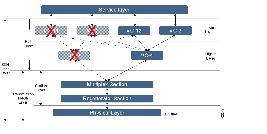
An SDH network has layered structure as shown in Figure 5-28. The layers operate in a client/server based scenario. The service layer generates the bit streams that are to be carried across the SDH network. This layer is not part of SDH. The path layer is a virtual layer and can only be observed through a management system. It is in this layer that the cross-connection management and structuring of the SDH ports is performed. The path layer works on containers.
Figure 5-28 SDH Layer Network
The ONS 15305 network element has support for VC-4 in the higher order layer and in the lower order layer VC-12 and VC-3.
5.7.1 SDH Port Structuring
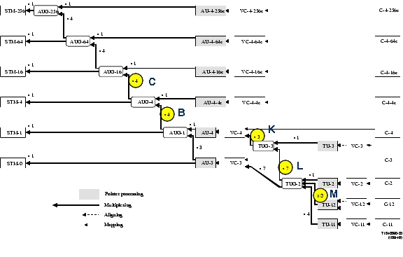
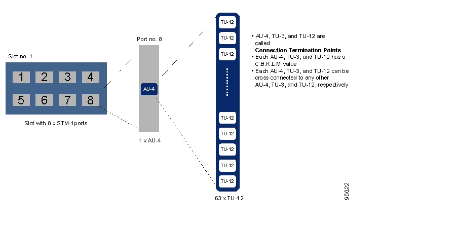
The multiplexing structure of the SDH ports determines which layers and their termination points are available to be cros- connected. The multiplexing structure for SDH in all layers is shown in Figure 5-29 (taken from ITU-T Recommendation G.707). The CBKLM value determines the path trough the structure. The usage of the CBKLM value follows the rules defined in Table 5-1.
Only traffic on non-terminated containers called connection termination points can be cross connected (AU-4, TU-3, and TU-12). The other containers, VC-4, VC-3, and VC-12, represent trail termination points where the traffic can be read.
Figure 5-29 SDH Multiplexing Structure
The original illustration used in Figure 5-29 is found in ITU-T G.707/Y1322 (10/2000).
5.7.1.1 C.B.K.L.M Value Usage
5.7.1.2 Cross-Connection Management
Cross-connection management is the management of connectivity within the network element itself. Cross-connections (XC) are set up between connection termination points with the same characteristic information, for example cross connections between AU-4s, TU-3s, VC-12 and TU-12, or two VC-12s.
Figure 5-30 Slot - Port - CTP Relations
The ONS 15305 has four slots that can hold an SDH module. The module can be of different types, that means, STM-1, STM-4, or STM-16. In this document the STM-1 module with 8 ports is used as an example.
In addition the ONS 15305 can have PDH modules with a number of E1 or E3 ports. The E1 and E3 ports have a corresponding VC-12 or VC-3, respectively. These VCs can be cross connected to termination points on the SDH modules or with each other.
5.7.1.3 8-Port STM-1 Module Example
A slot with an 8 x STM-1 module has eight ports. Available CTPs on port no.8 in slot no. 1 are shown in Figure 5-30. There is one AU-4 on the port and depending on the structuring of the AU-4 container, there are 63 TU-12s, 3 TU-3s, or a combination of TU-12s and TU-3s since the TUG-3s can be structured independently, which can be cross connected. This means that in this single slot there are 8 x 63 = 504 CTPs (maximum) in the lower layer and 8 x 1 = 8 CTPs in the higher layer. And what are the possible CTPs to be cross connected to ? If we assume that all four slots in this ONS15305 are equipped with 8 x STM-1 modules there are 3 x 504 = 1512 possible choices for the connecting CTP in the lower layer and 8 x 3 = 24 in the higher layer. If an ONS15305 is equipped with four STM-16 modules, each of these modules has 4 x 4 x 63 = 1008 TU-12 CTPs. This means that the cross connect matrix in the fabric has the dimension 4032 x 4032 ( Figure 5-31).
Figure 5-31 Largest Possible Cross Connect Matrix
There are several different types of cross connections:
•
•
•
•
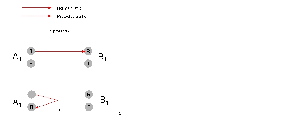
All of these types can be with or without protection and unidirectional or bidirectional. Un-protected, uni-directional cross connects can be used for test loops, as illustrated in Figure 5-32.
Figure 5-32 Unidirectional XC, Unprotected
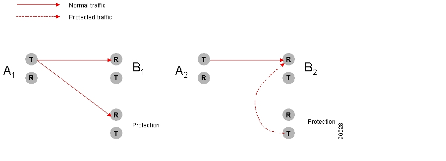
In Figure 5-33 protection has been set up for the termination point A1 and B2. The protected termination point A1 has no switching possibility since the cross connection is uni-directional, but termination point B2 has switching.
Figure 5-33 Unidirectional XC, Protected
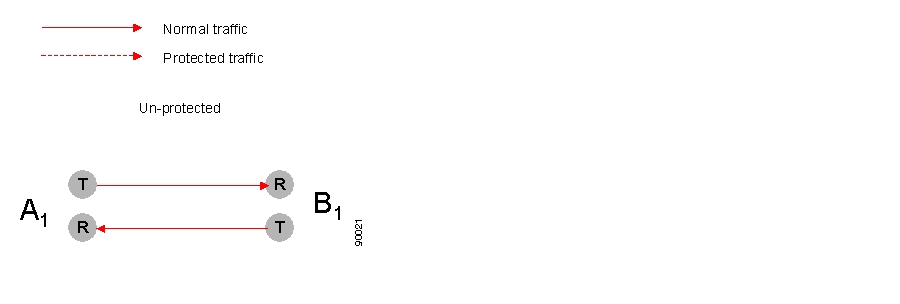
The bidirectional, unprotected cross connection is depicted in Figure 5-34. For bidirectional cross- connections all termination points have switching possibilities when protected.
Figure 5-34 Bidirectional XC, Unprotected
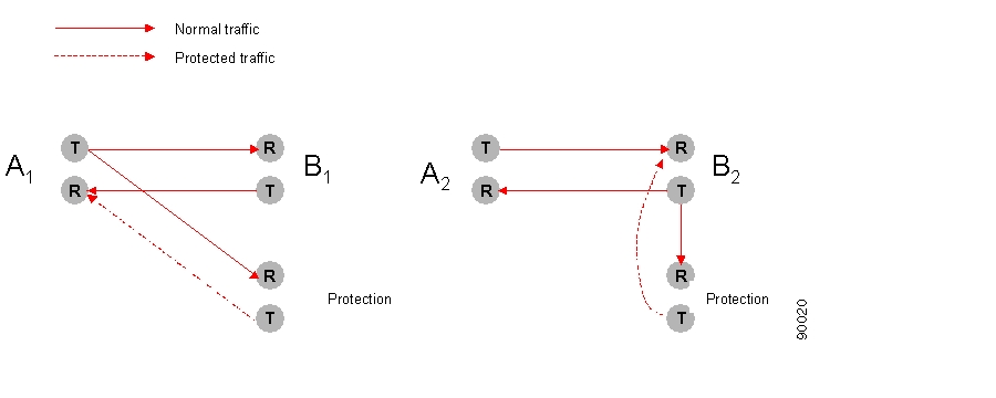
In Figure 5-35 the termination points A1 and B2 are protected, that means A1 can choose to receive from either B1 or the protection and B2 can switch between A2 or the protection.
Figure 5-35 Bidirectional, Protected
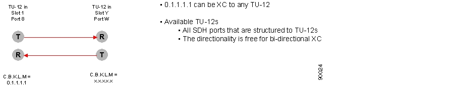
Examples of an unprotected, bidirectional, point-to-point cross connect and a protected, bidirectional, point-to-point cross connect are given in Figure 5-36 and Figure 5-37.
Figure 5-36 Example of Bidirectional, Unprotected, Point-to-Point XC
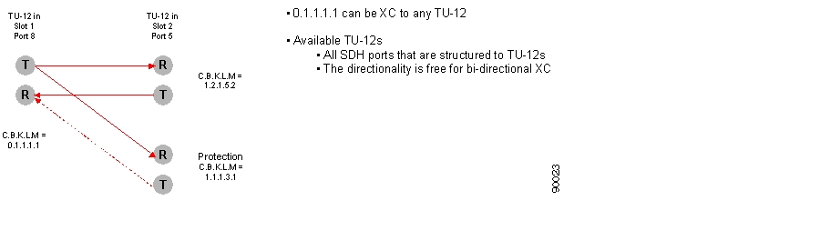
Figure 5-37 Example of Bidirectional, Protected, Point-to-Point XC
5.7.1.4 XC Fabric
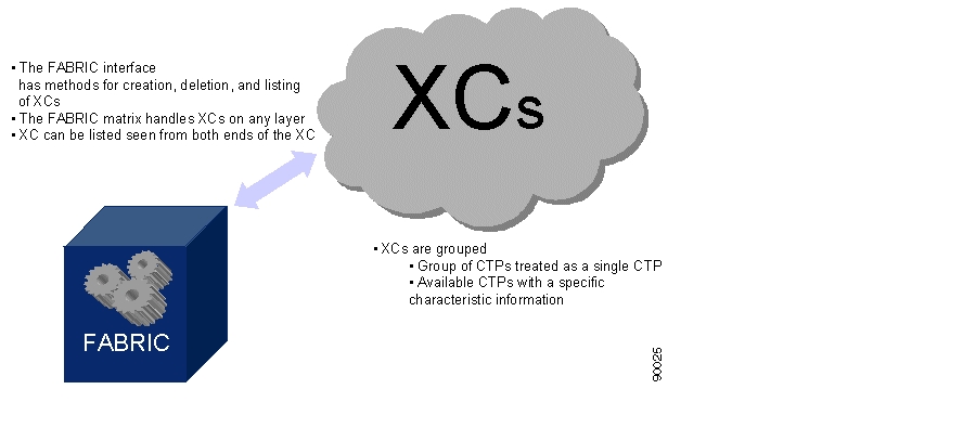
The connection management is taken care of by FABRIC as depicted in Figure 5-38. The FABRIC has an interface that offers a set of methods that helps you in the cros- connection management tasks on any layer. The FABIRC can create, delete, and modify cross-connections. It has several options for listing XCs, for example, all XCs with the same characteristic information or all available CTPs on one port of a specific characteristic information. A third possible listing of CTPs can be a pre-defined grouping of points. A user might be indifferent to which specific CTP is used in an XC as long as it is a member of a specific group of CTPs. The system will choose an arbitrary CTP in the group. This will simplify the selection of CTP for you.
Figure 5-38 XC Fabric
5.7.2 Open the Cross-Connection GUI
You have three possible choices for opening the Cross-Connection GUI.
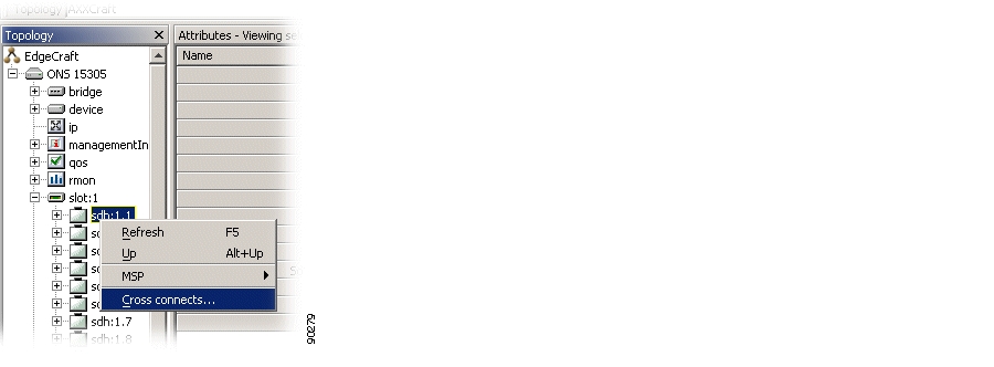
Step 1
Figure 5-39 Select Cross Connect
Step 2
Figure 5-40 Select SDH Port Cross Connect
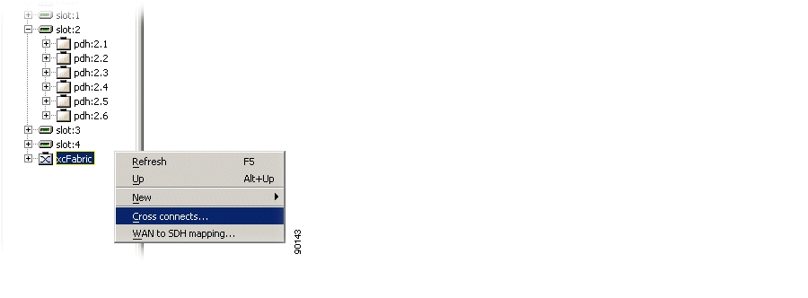
Step 3
Figure 5-41 Select XCFabric Cross Connect
The system presents the cross-connection GUI with the relevant data from the selected managed object in the topology browser.
The cross-connection GUI allows you to filter the selection based on a predefined set of queries.
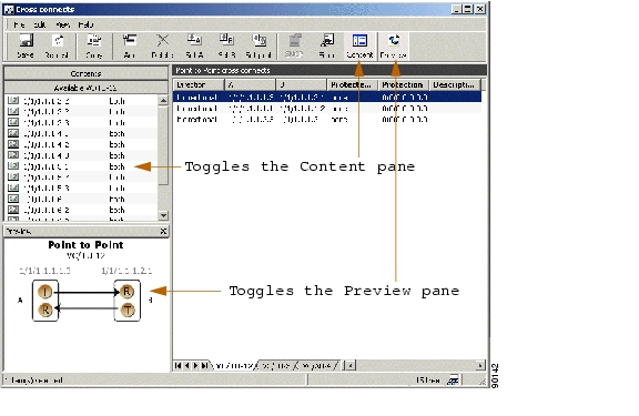
Figure 5-41 shows the cross-connection screen.
Figure 5-42 Cross-Connection GUI - Overview
5.7.3 Browse Existing Cross-Connections
This section explains how to browse and filter cross-connections.
5.7.3.1 Browse all Cross-Connections
Open the cross-connects window from the equipment menu. A list of all cross-connections appears.
For bidirectional cross-connections the termination points are located in the A column and the B column, according to how the cross-connection was created. One termination point can be in both the A and B-end column if the cross-connections are unidirectional. By default the cross-connections are sorted based on the A-end. Click the B column header to sort based on the B-end.
5.7.3.2 Browse Cross-Connections of a Port
Step 1
Step 2
A list of all cross-connections to and from the port is shown.
5.7.3.3 Filter the Content of the Cross-Connection List
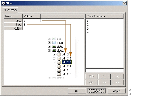
Step 1
Step 2
Step 3
Figure 5-43 Example of Filtering Criteria - Cross-Connections
.
Step 4
The cross-connects window shows only cross-connections where at least one of the termination points is included in the filtering criteria.
A filter icon appears in the status bar of the window to indicate that the filter is active.
5.7.3.4 Synchronize or Refresh the Cross-Connect Window
Synchronization of the cross-connect GUI will synchronize the available TP list and cross-connections list with the MIB in ONS 15305 ( Figure 5-44).
Step 1
Figure 5-44 Select Synchronize
.
Note
Step 2
Refreshing the window will refresh the available TP list and cross-connection list based on the last operations performed by the local user of Cisco Edge Craft.
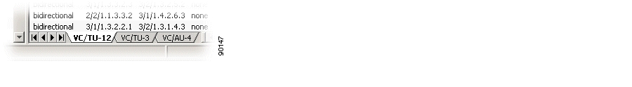
5.7.4 Set Up Cross-Connections from a 2 Mbps E1 Port to a Timeslot in an SDH Port
Creating a cross-connection from a 2 Mbps E1 port to a timeslot in an SDH port (TU-12 termination point).
Step 1
Step 2
Figure 5-45 Select the VC/TU12 Tab
.
Step 3
Step 4
Note
Note
Note
Step 5
Step 6
Step 7
Step 8
Note
5.7.5 Set Up Cross-Connections from a 45 Mbps E3 (T3) Port to a Timeslot in an SDH Port
Use the following steps to create a cross-connection from a 45 Mbps E3 (T3) port to a timeslot in an SDH port (TU-3 termination point).
Step 1
Step 2
Figure 5-46 Select the VC/TU12 Tab
.
5.7.6 Create a Pass-through Cross-Connection
Use the following steps to create a pass-through cross-connection from one SDH port to another SDH port.
Step 1
Step 2
5.7.7 Modify Cross Connections
A cross-connection is a relationship between termination points; the relationship cannot be modified after it has been created.
It is not possible to modify the direction (bidirectional or unidirectional) of a cross-connection in the supported release of ONS 15305. The only parameter that can be modified is the description of the cross-connection.
Cross-connections can be protected after they have been created.
5.7.8 Protect Cross Connections
The A-end or B-end of a cross-connection can be protected by the SNC protection scheme either before or after a cross-connection has been created.
Note
Note
Step 1
Step 2
Step 3
Step 4
Step 5
Note
Note
Step 6
Step 7
Step 8
Step 9
Note
5.7.8.1 Enable SNC Protection
Step 1
Step 2
Step 3
Figure 5-47 Select Enabled Attributes
.
Step 4
Note
5.7.8.2 Modify Protection Parameters of a Cross-Connection
A-end or B-end of cross-connections are protected as described in "Protect Cross Connections" section. The SNC is then set up with a number of default parameters. The parameters can easily be modified.
Step 1
Step 2
Step 3
Step 4
Step 5
Step 6
5.7.8.3 Command a Cross-Connection Protection Switch
With Cisco Edge Craft you can control the SNC protection switch by sending a command.
Step 1
Step 2
Step 3
Step 4
Figure 5-48 Select SNCP Command
.
Step 5
Depending on the priority of the command and current status of each channel, a switch may now take place for some or all selected cross-connections.
5.7.9 Delete Cross-Connections
Step 1
Step 2
Step 3
Step 4
Step 5
5.7.10 Advanced Cross-Connection Operations
For frequent users of Cisco Edge Craft, it is possible to make use of the enhanced editing facilities to speed up the configuration work.
5.7.10.1 Set Up Multiple Cross-Connections by Multiple Selection
Step 1
Step 2
Step 3
Step 4
Step 5
Step 6
Step 7
Note
If you want to modify the A or B termination point the cross-connection must be deleted and created again.
If you want to modify the protection termination point the ProtectedTP must first be saved as none. Then the protection TP can be modified. Remember to set the ProtectedTP back to a.
Note
5.7.10.2 Set Up Multiple Cross-Connections by Repeated Operations
Step 1
Step 2
Step 3
Step 4
5.7.10.3 Enter Termination Points Manually
Step 1
Step 2
Step 3
Step 4
Step 5
Step 6
Step 7
Note
5.8 ONS 15305 SDH Protection Management
This sectionexplains how to manage the 1+1 linear multiplex section protection (MSP) between two SDH ports. It includes managing the complete life cycle of an MSP, including creating, presenting, modifying, deletting, and manually operating the MSP switch.
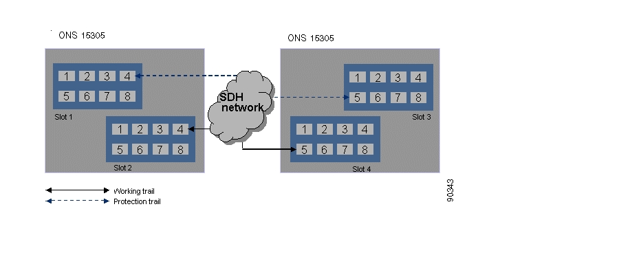
5.8.1 Multiplex Section Protection
The 1+1 MSP provides protection of the SDH ports by replacing the supporting trail when it fails, as illustrated in Figure 5-49. This is a 100% redundant protection scheme.
Figure 5-49 1+1 MSP Between two ONS 15305
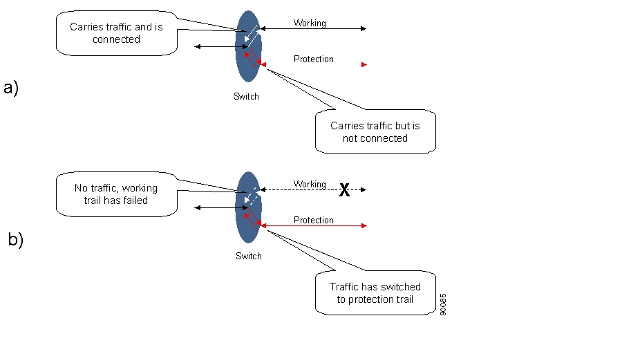
Both working and protection trails are enabled and the signal is bridged to both.
a.
Figure 5-50 Protection Switching Scenarios
b.
The switching has two different modes:
•
•
The time to wait before restoring the trail can be defined.
When switching either from or to protection, an event notification is generated.
5.8.2 Protect Section by MSP
Step 1
Step 2
Figure 5-51 Select SDH Port
.
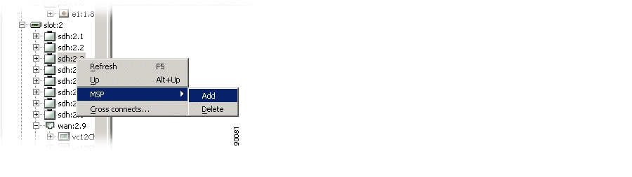
Step 3
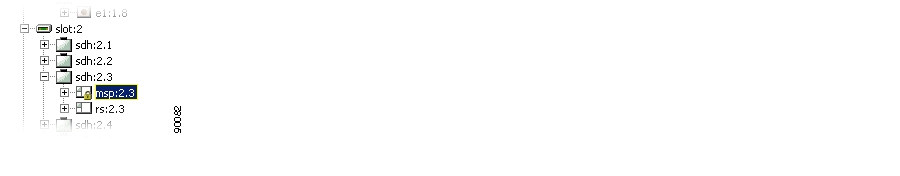
Figure 5-52 Select MSP Object
.
Step 4
Figure 5-53 Select Protection Port Attributes
Step 5
Step 6
The MSP scheme is created in ONS 15305 and starts working immediately. You will also see that the same msp object is now available under the protection port. You will also see that if the msp has the same Object identifier (for example 1.2.) as the parent sdh port, the port is a working port. If it has a number that is different from the parent sdh port (for example sdh port is 1.4 and msp is 1.2) it is a protection port for the sdh port with the same object identifier as the msp object.
Note
Note
Note
5.8.3 Modify MSP
Step 1
Step 2
Step 3
Step 4
Note
Note
5.8.4 Delete MSP
Step 1
Step 2
Step 3
Note
Note
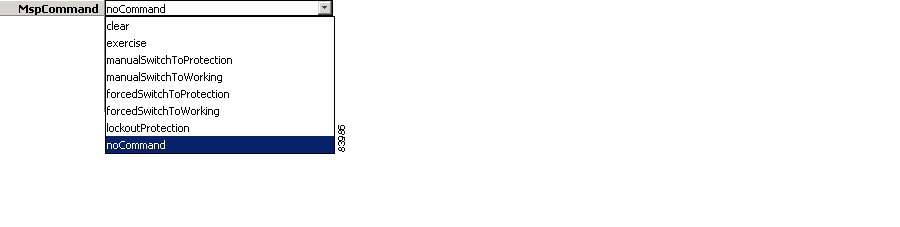
5.8.5 Command an MSP Switch
Step 1
Step 2
Step 3
Figure 5-54 Select MspCommands Attribute
.
Step 4
Note
Note
Note
5.8.6 Legal Combinations of SNCP and MSP
It is possible to use both SNCP and MSP in an ONS 15305 simultaneously, as long as the following is satisfied:
The protected SNCP entity can be part of an MSP protected port, but the working or protection entity cannot, for example, consider an STM-4 ring where some TU-12s are dropped off the ring and sent to an ONS 15302 via an STM-1 link. In this case, SNCP can be used in the ring, protecting the TU-12s to be dropped from the ring toward the ONS 15302. MSP can then be used for the STM-1 link to protect the traffic between the ONS 15305 and the ONS 15302. This is because the TU-12s that are dropped from the ring are the protected TU-12s, while the TU-12s in the ring are the working and protection TU-12s. Consequently, it is not possible to use MSP on the east or west links of the ring, since the TU-12s that are carried here are the working or protection part of the SNCP protected path's.
5.8.7 SubNetwork Connection Protection
SNCP is strongly related to the cross-connection that is protected in the network element. In Cisco Edge Craft SNCP related issues are handled from the cross-connections GUI.
Note
The resolution of the Hold-off timer is N x 100ms +/- 60 ms. That means for a 500 ms Hold-off timer, the real timer value may be any value between 440 ms and 560 ms. The Working, protection and protected parts of an SNCP protected path can be carried over different link rates. For example for an SNCP protected TU-12, the working TU-12 could be carried over an STM-16 link, while the protection TU-12 could be carried over an STM-4 link.5.8.7.1 Protect Connection by SNCP
See the "Enable SNC Protection" section.
5.8.7.2 Modify SNCP
See the "Modify Protection Parameters of a Cross-Connection" section.
5.8.7.3 Command an SNCP Switch
See the "Command a Cross-Connection Protection Switch" section.
5.9 ONS 15302 SDH Protection Management
The ONS 15302 offers 1+1 linear multiplex section protection (MSP). The protocol used for K1 and K2 (b1 to b5) is defined in ITU-T G.841, clause 7.1.4.5.1. The protocol used is 1+1 bidirectional switching compatible with 1:N bidirectional switching.
Use the following steps to configure the operation of the protection switch.
5.9.1 Modify MSP Parameters
Step 1
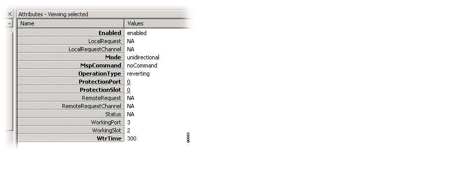
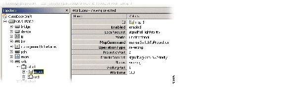
Figure 5-55 Select SDH1/MSP1 Attributes
Step 2
•
Set to enabled or disabled.
•
Set to unidirectional or bidirectional.
•
Set one of the following.
•
Set to reverting or non-reverting.
•
Wait to restore time; number of seconds to wait before switching back to the preferred link after it has been restored (0,1, ....,12 minutes, default 5 min (300 seconds)).
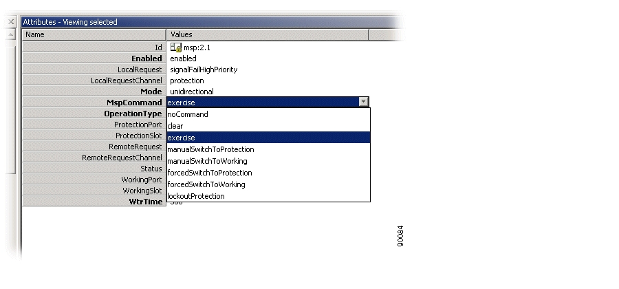
Figure 5-56 Set MSP Command
Step 3
![]()
![]()
![]()
![]()
![]()
![]()
![]()
![]()
Posted: Fri Sep 14 11:54:01 PDT 2007
All contents are Copyright © 1992--2007 Cisco Systems, Inc. All rights reserved.
Important Notices and Privacy Statement.