cc/td/doc/product/ong/15305/cecdocs
hometocprevnextglossaryfeedbacksearchhelp
PDF

Table Of Contents

Troubleshooting and FAQ


Troubleshooting and FAQ


Question one covers troubleshooting and FAQs from Chapter 4, "General Management."

Questions two to four cover troubleshooting and FAQs from Chapter 5, "Traffic Port Management."

Questions six to eleven cover troubleshooting and FAQs from Chapter 7, "Layer 2 Configuration."

Question 1

Q. I cannot configure the Slot for another module type.

A. When the Slot Expected Module attribute is set to a specific module type, the Managed Objects for the expected module type are created in ONS 15305. Likewise, when the Expected Module is already set to a module type and we want to configure the Slot for a different module type, the Managed Objects for the configured module will be deleted before the Managed Objects for the new module type can be created.
In order to avoid unintentional traffic breaks, ONS 15305 checks whether the existing configured module is involved in cross-connections, carrying management traffic or is used for synchronization purposes.

Question 2

Q. Why should I set the Path Trace Identifier attributes?

A. You do not have to set the Path Trace Identifier attributes, but it is a very useful tool for checking the connectivity of complex networks. Basically a Path Trace Identifier is inserted at the beginning of a path and extracted at the end of a path. By setting Path Trace Transmitted to a logical value, for example BONN-3-21 you can easily see if this value is received on the other side of the network.
If you enter a value for the Path Trace Expected value and enable Path Trace, a TIM alarm will be triggered if the received value is different from the transmitted value.

Question 3

Q. What is a WAN port?

A. WAN ports perform the mapping between a traditional Lan Port and the SDH network. The WAN port is an internal interface in ONS 15305.

Question 4

Q. Why does a WAN port have 50 channels when I can achieve the maximum capacity of 100 Mbit/s using 47 channels?

A. The WAN port is mapping the ethernet packets into VC12 containers. Each VC12 container always carry 2.16 Mbit/s. However, the mapping process requires some overhead. The overhead will vary with the actual PDU type mapped into the VC12 channels. This means that the bit rate at the Ethernet interface is a bit less than the bit rate of the VC-12 channel. With a certain type of PDUs, 100Mbit/s is achieved using only 47 channels, while some PDUs may require 50.

Question 5

Q. Why is the Mac multicast feature not available in Cisco Edge Craft

A. To enable MAC multicast, the user must make sure that the maximum number of VLANs is less than 4000. This is because the maximum number of multicast entries allowed in the network element is fixed by the following equation:

Figure A-1 VLAN Calculation

Therefore, if the maximum number of VLANs is greater than 4000, no resources can be allocated for MAC multicast entries, and the MAC multicast feature is then disabled.

The maximum number of VLANs is set via the vlanMaxEntriesAfterReset attribute (under Bridge->VlanType). If this attribute is edited, the network element must be reset before the new value becomes effective.

Question 6

Q. Why is the STP per VLAN (or STP per Device) attribute not available in Cisco Edge Craft.

A. Either the stpPerDevice or the stpPerVlan attribute is available in the Cisco Edge Craft, but both attributes are not available simultaneously. The attribute stpType under Bridge > spanningTree decides which attribute is available. When the value of the stpType attribute is 'perDevice', the stpPerDevice attribute is available, and the stpPerVlan attribute is not. Reciprocally, when the value of the stpType attribute is 'perVLAN', the stpPerVLAN attribute is available, and the stpPerDevice attribute is not.

The attributes stpPerDevice and stpPerVLAN allows the user to control the spanning tree process(es) on the network element. The network element can either run one single spanning tree for the whole network element, or one spanning tree per VLAN. The stpType attribute is used to indicate which type of spanning tree protocol (per device or per VLN) is currently running. To modify the current type, set the stpTypeAfterReset attribute (under Bridge > spanningTree) to the desired value, and reset the network element.

Question 7

Q. How many VLAN does the network element support?

A. The maximum number of VLANs supported by the network element is configurable by the user, and is indicated by the vlanMaxEntries attribute (under Bridge > VlanType).The maximum number of VLANs can be set to a new value via the vlanMaxEntriesAfterReset attribute (under Bridge > VlanType). If this attribute is edited, the network element must be reset before the new value becomes effective. Note that the network element cannot support more than 4000 VLANs.

Question 8

Q. What is the VLAN ID?

A. IEEE 802.1Q standardizes a scheme for adding additional information, known as VLAN tag, to layer 2 frames in order for a switch to know which VLAN an incoming frame is intended for, and the priority of the frame. The VLAN tag is a two-byte field containing 3 bits for indicating the priority of the frame, 12 bits for indicating the VLAN ID, and 1 bit indicating whether the addresses are in canonical format, Figure A-2.


Note In the standard (IEEE 802.1Q), layer 2 frames carrying both VLAN identification and priority information in a tag are referred to as VLAN tagged frames. Layer 2 frames carrying priority information, but no VLAN identification information are referred to as priority tagged frames.


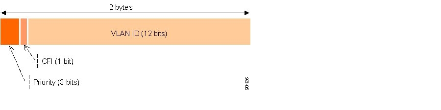
Figure A-2 IEEE 802.1Q Tag header (VLAN tag)

The priority field is interpreted as a binary number, and therefore capable of representing eight priority levels, 0 through 7. The use and interpretation of this field is defined in ISO/IEC 15802-3.

The canonical format indicator (CFI) is a single bit flag value. CFI reset indicates that all MAC address information that may be present in the MAC data carried by the frame is in canonical format.

The VLAN identifier (VLAN ID) field uniquely identifies the VLAN to which the frame belongs. The VLAN ID is encoded as an unsigned binary number. The user can associate any value in the range 1-4095 to a VLAN ID. The value null is reserved for priority-tagged frames, and the value 4096 (FFF in hexadecimal) is reserved for implementation use.


Note Priority tagged frames are layer 2 frames carrying priority information, but no VLAN identification information.


Question 9

Q. How to choose the maximum number of GVRP VLAN?

A. The generic attribute registration protocol (GARP) protocol is a general-purpose protocol that registers any network connectivity or membership-style information. GARP defines a set of devices interested in a given network attribute, such as VLAN or multicast address.

The GARP VLAN registration protocol (GVRP) protocol is specifically provided for automatic distribution of VLAN membership information among VLAN-aware bridges. GVRP allows VLAN-aware bridges to automatically learn VLANs to bridge ports mapping, without having to individually configure each bridge, and to register VLAN membership.

To minimize the memory requirements when running the GVRP protocol, two proprietary tuning variables have been added to the standard variables: gvrpVlanMaxEntries and gvrpVlanMaxEntriesAfterReset which control the number of GVRP VLANs allowed to participate in GVRP operation. The maximum number of GVRP VLANs includes all the VLANs participating in GVRP operation regardless if they are static or dynamic.

The following should be considered when specifying the maximum number of VLANs participating in GVRP by setting the gvrpVlanMaxEntriesAfterReset attribute:

The default maximum number of GVRP VLANs is equal to 0 because of the memory restrictions.

The maximum number of VLANs (managed through the bridge> vlanType > maxVlanEntriesAfterReset attribute) limits the maximum number of GVRP VLANs.

To ensure the correct operation of the GVRP protocol, users are advised to set the maximum number of GVRP VLANs equal to a value which significantly exceeds the sum of:

The number of all static VLANs both currently configured and expected to be configured.

The number of all dynamic VLANs participating in GVRP both currently configured (initial number of dynamic GVRP VLANs is 0) and expected to be configured.

In creasing the value of maximum number of GVRP VLANs to value beyond the sum, allows users to run GVRP, and not reset the device to receive a larger amount of GVRP VLANs. For example, if 3 VLANs exist and another two VLANs are expected to be configured as a result of VLAN static or dynamic registration, set the maximum number of GVRP VLANs after reset to 10.

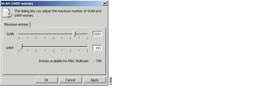
Adjust the maximum number of VLAN and GVRP entries


Step 1 Click Properties in the VLAN Settings window.

Step 2 The appearing dialog allows you to adjust the maximum number of VLAN and GVRP entries.

Figure A-3 Adjustment of VLAN/GVRP entries


Note To enable GVRP, ensure that the amount of maximum amount of VLANs is less than 4000 (check the bridge > vlanType > maxVlanEntries attribute).


Question 10

Q. How to represent a set of ports with an octet string?

A. When an octet string is used to represent a set of ports, each octet within the string specifies a set of eight ports, with the first octet specifying ports 1 through 8, the second octet specifying ports 9 through 16, etc. Within each octet, the most significant bit represents the lowest numbered port, and the least significant bit represents the highest numbered port, Figure A-4. Each port of the bridge is then represented by a single bit within the octet string. If the bit has a value of 1 then the port is included in the set of ports, and the port is not included if the bit has a value of 0.

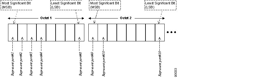
Figure A-4 Definition of a Set of Ports Through an Octet String

Table A-1 presents two examples of octet strings and their corresponding sets of ports.

Table A-1 Octet String and Corresponding Set of Ports

Octet String

Binary Representation

Set of port(s)

52

0101 0010

port #2, port #4, and port #7

0c 01

0000 1100 0000 0001

port #5, port #6 and port #16


Question 11

Q. What are the Common UDP Ports?

A. The common UDP ports are described in Figure A-5.

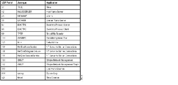
Figure A-5 Common UDP Ports

Q. What are the different types of Link State Advertisements?

A. The different link types are listed in Table A-2.

Table A-2 Link State Type (according to RFC2328, Appendix A.4.1)

Link State (LS) Type
Description

1

Router-LSAs

2

Network-LSAs

3

Summary-LSAs (IP network)

4

Summary-LSAs (ASBR)

5

AS-external-LSAs


hometocprevnextglossaryfeedbacksearchhelp

Posted: Fri Sep 14 13:35:20 PDT 2007
All contents are Copyright © 1992--2007 Cisco Systems, Inc. All rights reserved.
Important Notices and Privacy Statement.