|
|

Table Of Contents
Dual Optical LAN 1000Base-LX Module
with Mapper, GigE-WAN-220.2.1 2xGE Without Mapper Circuits
20.2.2 2xGE With Mapper Circuits
Dual Optical LAN 1000Base-LX Module
with Mapper, GigE-WAN-2
20.1 Module Description
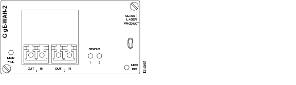
The module (see Figure 20-1) is a tributary module that supports both optical and electrical gigabit Ethernet interfaces. It supports up to two interfaces.
It includes up to two Gigabit Ethernet to SDH mappers. The module support both L1 and L2 services.
It consists of the following functionality:
•
Ethernet features
•
•
•
•
•
•
Figure 20-1 Dual Optical LAN 1000Base-LX Module with Mapper, GigE-WAN-2
20.1.1 Ethernet Features
The module supports both L1 and L2 services. The number of physical interfaces is two. The tributary module includes the following Ethernet functionality:
•
•
•
•
•
•
•
The module includes two Ethernet switches and both are connected to the policer. The mappers and physical interfaces are also connected to the policer.
The following options are available in the policer:
•
•
•
20.1.2 SDH Features
The tributary module includes the following SDH functionality:
•
•
•
•
•
•
•
•
•
20.1.3 Power Consumption
The module power consumption is 25 W.
20.1.4 External Interface
There is room for two interfaces in the module. Both interfaces only support full duplex GE.
The interfaces are based on the SFP multi source agreement (MSA) and it is possible to add the modules in the field. The modules supports hot insertion. The following interfaces are supported in the first release:
•
•
20.1.5 LED Indicators
Visual indicators (LED's) provide the status of the service module.
20.2 Configuration
In addition to the two GE interfaces the module contains two single port Ethernet switches, and two single port mapper circuits.
All Ethernet switches in the ONS 15305 are inter-connected via the main card.
The module is configurable in two main operation modes:
•
•
20.2.1 2xGE Without Mapper Circuits
In this operation mode the 2 physical input ports are connected directly to the two Ethernet switch ports. In this configuration none of the mapper circuits are available.
20.2.2 2xGE With Mapper Circuits
In this operation mode the physical port 2 will always operate as a L1 port, connected to mapper circuit number 2. It is possible to configure physical port 1 to operate either as a L1 port or as a L2 port. When port 1 is configured to operate in L1 mode it is directly connected to mapper circuit number 1, the Ethernet switch are not used. When port 1 is configured in L2 mode, the physical port is connected to Ethernet switch number 1. Ethernet switch number 2 is connected to mapper circuit number 1.
The mapper circuits support the mapping functionality described in 5.2 Ethernet over SDH mapping, page 5-17. The LAN and WAN ports offer the IP functionality described in 5.4 IP Features, page 5-24.
20.3 External Interface
This section contains descriptions of the external module interfaces.
20.3.1 Description
The module contains two Gigabit Ethernet (GE) LAN interfaces that meets the specification in IEEE 802.3.
The interfaces use Small Form Pluggable (SFP) optics with the following optics offered:
•
•
20.3.2 1000Base-SX
The interface offered is a Gigabit Ethernet (GE) interface that meets the 1000Base-SX specifications in IEEE 802.3. This interface is an optical short haul interface based on multi-mode fibre. Operating range and Transmitter characteristic for 1000Base-SX are found in Table 20-1 and Table 20-2. Receiver characteristic is found in Table 20-3.
Table 20-2 Transmitter characteristic for 1000Base-SX
Transmitter type
Shortwave Laser
Signaling speed (range)
1.25 ± 100 ppm
GBd
Wavelength (range)
770 to 860
nm
Trise/Tfall (max; 20%-80%; > 830 nm)
0.26
ns
Trise/Tfall (max; 20%-80%; < 830 nm)
0.21
ns
RMS spectral width (max)
0.85
nm
Average launch power (max)
See footnote1
dBm
Average launch power (min)
-11.5
dBm
Average launch power of OFF transmitter (max) 2
-30
dBm
Extinction ratio (min)
9
dB
RIN (max)
-117
dB/Hz
Coupled Power Ratio (CPR)3
9 < CPR
dB
1 The 1000BASE-SX launch power shall be the lesser of the class 1 safety limit as defined by 802.3 38.7.2 or
the average receive power (max) defined by 802.3 Table 38-4.2 Examples of an OFF transmitter are: no power supplied to the PMD, laser shutdown for safety conditions, activation of a
"transmit disable" or other optional module laser shut down conditions. During all conditions when the PMA is powered,
the ac signal (data) into the transmit port will be valid encoded 8B/10B patterns (this is a requirement of the PCS layers)
except for short durations during system power-on-reset or diagnostics when the PMA is placed in a loopback mode.3 Radial overfilled launches as described in 802.3 38A.2, while they may meet CPR ranges, should be avoided.
20.3.3 1000Base-LX
The interface offered is a Gigabit Ethernet (GE) interface that meets the 1000Base-LX specification in IEEE 802.3. This interface is an optical long haul interface based on single-mode fibre.
Operating range and transmitter characteristic for 1000Base-LX are found in Table 20-4 and Table 20-5.
Table 20-5 Transmitter characteristic for 1000Base-LX
Transmitter type
Longwave Laser
Signaling speed (range)
1.25 ± 100 ppm
GBd
Wavelength (range)
1270 to 1355
nm
Trise/Tfall
(max, 20-80% response time)0.26
ns
RMS spectral width (max)
4
nm
Average launch power (max)
-3
dBm
Average launch power (min)
-11.5
-11.5
-11.0
dBm
Average launch power of OFF transmitter (max)
-30
dBm
Extinction ratio (min)
9
dB
RIN (max)
-120
dB/Hz
Coupled Power Ratio (CPR) 1
28 < CPR< 40
12 < CPR < 20
N/A
dB
1 Due to the dual media (single-mode and multimode) support of the LX transmitter, fulfillment of this specification requires a single-mode fiber offset-launch mode-conditioning patch cord described in 802.3 chapter 38.11.4 for MMF operation. This patch cord is not used for single-mode operation.
The receiver characteristic is found in Table 20-6.
20.4 SFP Modules
The SFP modules to be used together with the GigE-WAN-2 service module are available from Cisco.
Warning
For details on installation of SFP modules, please see the documents listed below:
Installing GBIC, SFP and XFP Optics Modules in Cisco ONS 15454, 15327, 15600, and 15310 Platforms:
http://www.cisco.com/univercd/cc/td/doc/product/ong/15400/454spint/gbicsfp.htm
and Cisco Small Form-Factor Pluggable Modules Installation Notes:
![]()
![]()
![]()
![]()
![]()
![]()
![]()
![]()
Posted: Fri Sep 14 08:56:43 PDT 2007
All contents are Copyright © 1992--2007 Cisco Systems, Inc. All rights reserved.
Important Notices and Privacy Statement.