|
|

Table Of Contents
2.3 Alarm and Fan Module, FAN-ALARM
2.4.1 Technical Overview DC/DC
2.5.4 Electrical Specifications - AC input
2.6 Limitations - Module Configurations
2.6.1 List of Power Consumption - Available ONS 15305 Modules
2.6.2 Example of Module Configuration Within Capacity of AC 230V Module
2.6.3 Example of Module Configuration Within Capacity of DC Power Module
2.7 System Controller Module, (SYSCONT-SD128-RJ45)
Product Overview
This chapter describes the functionality and the features of the ONS 15305.
2.1 Functional Overview
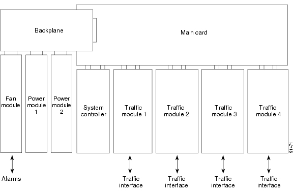
The ONS 15305 is a traffic concentrator that supports different types of transmission media. It can be used in networks based on fibre and copper media. The ONS 15305 concentrates both IP and TDM traffic and is able to interface to both TDM and IP backbone networks. The TDM part of the ONS 15305 is a cross-connect that can work as a terminal mux, add and drop mux or non-blocking cross-connect. The IP part consist of a L2 switch. The ONS 15305 is a small device with a high port density. It is targeted for a number of different applications as shown in this chapter. The ONS 15305 is a scalable system due to its modular design. The ONS 15305 consists of a chassis with a motherboard with room for up to eight plug-in modules. Four of the plug-in modules are used for interface modules. The remaining four modules are used for two redundant power supply modules, one fan and a system controller. The ONS 15305 can be used in star networks, ring networks, chained networks and meshed.
The following types of modules/boards exist:
•
Alarm and fan module, FAN-ALARM
•
•
•
•
•
•
See Figure 2-1.
Figure 2-1 System Overview
2.2 Applications
The following sections show examples of ONS15305 Applications.
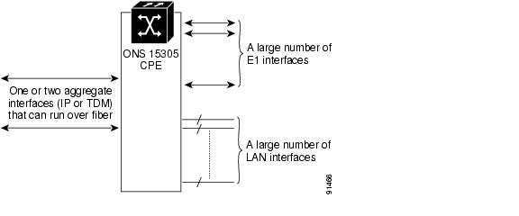
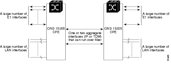
2.2.1 CPE Application
The ONS 15305 can be used as a Customer Premises Equipment (CPE). The unit have a large number of TDM interfaces (E1) and LAN interfaces (10/100/Base-T,1000 Base-LX). This application is typical used for very large end customers or in a building with many smaller end customers.
The ONS 15305 can be connected to the backbone network through fibre or copper. The application is shown in Figure 2-2.
Figure 2-2 CPE Application
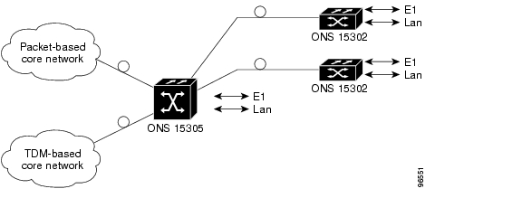
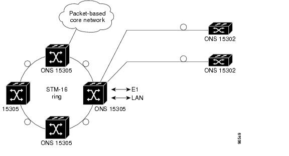
2.2.2 Small PoP Application
The ONS 15305 can also be used as a traffic concentrator in the point of presence (PoP) of the operator. The unit may support many different CPE's and may also support different types of transmission media. The unit is the interface between the core network and the access network. A typical application is shown in Figure 2-3.
In this application the ONS 15305 is used to connect up other Cisco product to the core SDH or IP network. It is also possible to connect equipment from other vendors to the ONS 15305.
Figure 2-3 PoP Application
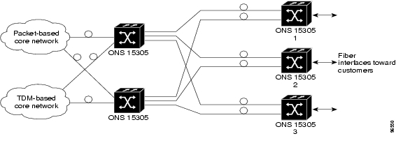
2.2.3 Large PoP Application
There are applications where one ONS 15305 does not have enough performance or does not support enough interfaces. It is possible to stack a number of ONS 15305's to create larger systems.
Typical an internal ONS 15305 is used to groom traffic from a number of ONS 15305's that is connected to the access network. The internal ONS 15305 is connected to the core network. Two ONS 15305 nodes are used for redundancy.A typical application is shown in Figure 2-4.
Figure 2-4 Large PoP Application
2.2.4 Campus Application
The ONS 15305 can also be connected back to back without any connection to external networks. A typical application is shown in Figure 2-5.
Figure 2-5 Campus Application
2.2.5 ADM Application
The ONS 15305 can be used as a standard ADM with support of both TDM tributaries and IP tributaries. A typical application is shown in Figure 2-6.
Figure 2-6 Typical ADM Application for the ONS 15305
2.3 Alarm and Fan Module, FAN-ALARM
The main feature of the fan unit is to ventilate the 19"/ 1U cabinet used for ONS 15305. The fan unit is a plug-in device consisting of a circuit board with 4 fans. The air is sucked in through 4 circular openings in the left sidewall, and emerges through holes in the right side cabinet wall. Four fans are used to improve reliability. During normal operation one or two pair of fans operate at the time. At inside cabinet temperatures below ~40oC, one pair operates. Above ~40oC both pairs operate.
Location of Alarm and Fan Module is shown in Figure 2-7.
2.3.1 Protection
The fan unit consists of four fans. To equalize wear-out time between both fan pairs, they interchange active/stand-by roles every 24-hour. In case of an abnormal temperature rise, all fans will operate simultaneously. The fans operate in pairs; there are two standby fans and two main fans. The maximum temperature measured in the ONS 15305 controls the fans. The only modules not containing temperature sensing are the fan unit itself, the power modules and the system controller card. The FAN module is connected to the main card through the backplane. The O_TEMP_ALM alarm is detected on the main card when temperature rises above 85 oC. The alarm, specific for each fan, is processed and presented "Fan Failure Alarm".
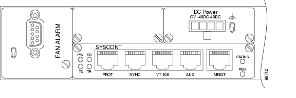
2.3.2 External Alarms
The ONS 15305 provides facilities to report four auxiliary alarm inputs for associated equipment, for example power module failure, battery condition, open cabinet door etc.
It also supports 2 alarm outputs used to signal equipment alarms and traffic related alarms. The alarm input/output connector is placed on the fan unit front cover as shown in Figure 2-7.
Figure 2-7 Location of Alarm and Fan Module, FAN-ALARM
2.4 Power Module, DC Power
The main feature of the power module is to convert and isolate primary power, 48V, to 5,25 volts for the modules in the product. Location of the DC Power Module is shown in Figure 2-8. The module has features that allow power sharing and hot plugging. The module has separate alarms for 2 independent primary supplies (< 40 volts) and alarm for the secondary output (< 4,65 volts). Alarms related to the power module(s) are displayed in CEC. The secondary is short circuit proof and the average s.c. current is less than 1 amp. The maximum secondary current is limited to ab. 26 amps. A power cable is provided with a Mini-fit connector in one end and no connector in the other end. This cable connects the ONS 15305 to the internal 48V power-rails inside the rack. The cable and the power-supply meet the safety requirements from the EN 60950 specification.
Figure 2-8 Location of DC Power
2.4.1 Technical Overview DC/DC
The -48V DC Power supply (DC) covers the -40,5 Vdc to -60Vdc range, also referred to as -48Vdc.The module generate +5.25Vdc, all other voltages necessary are generated on each module. If using two power modules, the current sharing between the two modules is between 40% and 60%.
Note
2.4.2 Connectors
The -48V DC supply input is provided through a 4- pin power connector, (Molex Mini-fit) with the pin-out shown in Table 2-1.
2.4.3 Parameters
The -48V DC input conform to the specifications given in Table 2-2.
Table 2-2 Electrical Specifications at DC Input
Power dissipation
Less than 120W
Fuse
7A
Battery voltage range
-40,5 to -60V DC
2.4.3.1 Power Supply Output
100 W.
See "Power Consumption - ONS 15305 Modules" section and "Module Configuration Within Capacity of DC Power module" section.
2.5 Power Module, AC 230V
This section describes the Power Module AC 230V shown in Figure 2-9.
2.5.1 Module Description
The module contains a 75 W AC/DC converter that converts the input voltage from 230V to +5.25V.
The module disconnects the output voltage and activates an alarm if the output voltage is outside the specified tolerance (Higher than 6V or less that 5V). The module also limits the maximum output current to 11A. Alarms related to the power module(s) are displayed in CEC. Two modules can share the output current and the current sharing is between 40 and 60%. A 0,65 M long power cable is provided with a standard mains connector. This cable connects the ONS15305 to the internal 230V power-sockets rails inside the rack or to external mains sockets. The cable and the power supply meet the safety requirements from the EN 60950 specification.
Note
2.5.1.1 Power Supply Output
75 W.
2.5.1.2 Power Supply Input
220-240VAC;0,5A;50/60Hz
2.5.2 External Interface
The 230V mains supply input is provided through a fixed 0,65 M power cable with an IEC C14 mains connector.
2.5.3 Connector Type
The physical connector is an IEC C14 mains connector.
Figure 2-9 AC 230V
Module
2.5.4 Electrical Specifications - AC input
Table 2-3 Electrical Specifications - AC input
Power dissipation
Less than 75W
Fuse
1.0A (Slow)
Mains voltage
-230V AC +/- 10%
Electrical Specifications - AC input is shown in Table 2-3.
2.5.4.1 Compliance
AC 230V Compliance is shown in Table 2-4.
Table 2-4 AC 230V Compliance
EN/IEC 60950
Single phase 230 V 50 Hz AC mains supply
ETS 300 253
Earthing and bonding of telecommunication equipment in telecommunication centers
2.6 Limitations - Module Configurations
The AC 230V module can provide 75 W to the ONS 15305 unit. The Power module DC Power can provide 100W to the ONS 15305 unit. This is not sufficient for all types of configurations. Table 2-5 provides a power consumption list for the base unit and modules. Table 2-6 provides a module configuration within capacity of AC the 230V module. Table 2-7 provides a module configuration within capacity of the DC 48 V module.
2.6.1 List of Power Consumption - Available ONS 15305 Modules
Table 2-5 Power Consumption - ONS 15305 Modules
Base unit1
20
E3/T3-6
11
S16.1-1-LC
13
S4.1-2-LC
9,5
GigE-2-LC
11
E100-8
5,5
E1-8
3,5
E1-63
21
S1.1-2-LC
9
S1.1-8-LC
25
L16.2-1-LC
18
L4.2-2-LC
13
S1.1-2-LC/E1-21
15
GigE-WAN-2
25
E100-WAN-8
27,5
1 Including Fan Alarm - and System Controller module
Power Consumption for the ONS 15305 Modules are shown in Table 2-5.
2.6.2 Example of Module Configuration Within Capacity of AC 230V Module
Table 2-6 Module Configuration Within Capacity of AC 230V module
Base unit
20
E1-8
3,5
S16.1-1-LC
13
S1.1-8-LC
25
GigE-2-LC
11
Total
72,5 W
Example of Module Configuration is shown in Table 2-6.
2.6.3 Example of Module Configuration Within Capacity of DC Power Module
Table 2-7 Module Configuration Within Capacity of DC Power module
Base unit
20
S16.1-1-LC
13
S16.1-1-LC
13
GigE-WAN-2
25
GigE-WAN-2
25
Total
96 W
Example of Module Configuration is shown in Table 2-7.
2.7 System Controller Module, (SYSCONT-SD128-RJ45)
Figure 2-10 shows the system controller that contains the processor for the ONS 15305. The software of the ONS 15305 runs in 128 MB SDRAM. The amount of memory can be configured from 64 MB to 512 MB. This is done in the factory.The software is stored in Flash memory devices. The ONS 15305 uses a Compact Flash card as the storage medium. The 32 MB CompactFlash is mounted in a connector on the system controller. The size of the Compact Flash cards can be from 8 MB to 128 MB.
The module supports a serial RS-232/VT100 interface for local access. A VT100 terminal can be used for initial configuration.
The system controller also supports a 10Base-T LAN interface used for management purposes. The system controller contains the local synchronization interface for the ONS 15305. This interface is directly connected to the SETS functionality on the mainboard. The system controller contains the local user interface for the ONS 15305, the AUX port. The interface supports a framed E1 interface. It is possible to select different overhead bytes from all SDH interfaces to the 30 available time slots. The physical connectors of the five interfaces are of the RJ-45 type. The system controller also provides four LEDs to indicate the status of the ONS 15305. The LED's are visible from the rear of the ONS 15305. The LEDs have the same functionality as the LEDs in the chassis. The fifth LED indicates the status of the management port.
Figure 2-10 Location of SYSCONT-SD128-RJ45
2.7.1 Power Consumption
6 W
2.7.2 Technical Overview
This sub.section gives a technical overview of the System Controller Module, (SYSCONT-SD128-RJ45).
2.7.2.1 Management Port
A local Ethernet port (10BaseT), called the Management Port, is available for connecting to a management DCN.
The management signals goes to an Ethernet Controller in the MPC8265 processor situated on the module.
2.7.2.2 VT100 port
The ONS 15305 offers a VT-100 interface for connection of Cisco EdgeCraft Terminal/CLI interface. The interface is running at a data rate of 19.200 baud.
2.7.2.3 Synchronization Port
The synchronization port is used for SETS functionality on the main card.
2.7.2.4 The 2Mbit/s AUX port
The 2Mb/s AUX signals go to the SETS FPGA.
2.7.2.5 Proprietary Protection Port
The proprietary protection interface is used for equipment protection.
For use in future release.2.7.2.6 Power
The voltages are generated on board with the exception of the +5.2V that comes directly from the power module(s). The module is equipped with a reset-circuit resetting the card in case of a fault in one of the voltages.
2.7.2.7 Reset
Caution
A special tool like a small screwdriver or a pencil may be used to activate the switch, Figure 2-11.
Figure 2-11 Location of the Reset Push Button
2.7.2.8 LEDs
LEDs are visual indicators that show ONS 15305 failure conditions. These LEDs are placed on the System Controller Unit front cover and the front of the ONS 15305, Figure 2-12. These LEDs are placed on the main card and have the same functionality as the ones on the system controller card. The color and functionality of the LED's are described in Table 2-8.
Figure 2-12 Locations of LEDs - System Controller Front
The LEDs are controlled by the SETS FPGA and are not affected by the external alarms.
A fifth, green LED is also mounted in the front of the system controller card. This LED indicates the link status of the management port.
2.8 Service Modules
2.8.1 Introduction
The ONS 15305 consists of a unit with a main card with space for up to four plug-in modules (service modules). The plug-in modules support a number of different external interfaces and different transmission media. The internal interface with the main card is identical for all service modules. This chapter will treat the standardized blocks for the Service modules.
Please see detailed descriptions for each service module, starting in chapter 8.
2.8.2 Common Functions
This sub-section describes Service Modules common functions.
2.8.2.1 Memory
All modules store inventory data in non-volatile memory, EPROM.
2.8.2.2 FPGA Configuration
The modules containing one or more FPGAs also contain a local flash used to store FPGA configuration data in two banks.
The FPGA configuration is automatically loaded from the active flash bank upon power-up. New FPGA files can be downloaded from the management system. Also the flash bank selection is controlled by the management system.
2.8.2.3 Processor Interface
The modules are connected to the main card through a 16-bit wide time multiplexed address and data bus. The DXC devices on the main card are responsible for generating module chip select and the translation from a time multiplexed bus towards the modules to a separate data and address bus towards the processor.
2.8.2.4 DCC
The modules terminating one or more STM-N lines are able to terminate both the DDC-R (192 kbit/s), and DCC-M (576 kbit/s) channels.
2.8.2.5 G.Link
All modules with IP switching capability are interconnected with a high speed link, to a crossbar on the Main card. The link is called G-link.
2.8.2.6 TDM
The mapping of IP traffic into VC12 containers is performed at service module level. There is no connection between the IP and SDH traffic on the main card. (in the base unit).
All modules with IP switching capability are interconnected with a high speed link, to a central switch on the Main card. All modules with TDM-functionality are connected to the cross-connect on the Main card.
![]()
![]()
![]()
![]()
![]()
![]()
![]()
![]()
Posted: Fri Sep 14 10:23:02 PDT 2007
All contents are Copyright © 1992--2007 Cisco Systems, Inc. All rights reserved.
Important Notices and Privacy Statement.