|
|

Table Of Contents
Installing GBIC, SFP and XFP Optics Modules in Cisco ONS 15454, 15327, 15600, and 15310 Platforms
GBIC Description and Specifications
GBIC Port Cabling Specifications
SFP Description and Specifications
SFP Port Cabling Specifications
XFP Description and Specifications
XFP Port Cabling Specifications
GBIC, SFP and XFP Installation and Removal
Connecting Single-Mode and Multimode Optical Fiber
Installing GBIC, SFP and XFP Optics Modules in Cisco ONS 15454, 15327, 15600, and 15310 Platforms
This document provides compatibility information and installation procedures for gigabit interface converter (GBIC), small form-factor pluggable (SFP), and 10 Gigabit small form-factor pluggable (XFP) optics modules in the Cisco ONS 15454, 15327, 15600, and 15310-CL. It also contains removal instructions, cabling, and technical specifications. Use this document in conjunction with platform-specific Cisco user documentation when working with GBICs and SFPs/XFPs or any other system components.
GBICs and SFPs/XFPs are hot-swappable input/output devices that plug into a line card port to link the port with the fiber-optic network. For all cards, the type of GBIC or SFP/XFP plugged into the card is displayed in CTC and in TL1.
The sections included in this document are:
•
GBIC Description and Specifications
–
•
–
•
–
•
•
Compatibility by Card
Table 1 lists Cisco ONS 15454, 15327, 15600, and 15310-CL cards with their compatible GBICs, SFPs and XFPs.
Caution
Table 1 GBIC, SFP, and XFP Card Compatibility
(Cisco Product ID)ASAP (ONS 15600 SONET/SDH)
ONS-SE-2G-L2
ONS-SE-Z1
ONS-SI-622-L2
ONS-SI-155-L210-2013-01
10-1971-01
10-1936-01
10-1937-0115310-CL-CTX (ONS 15310-CL SONET)
ONS-SI-155-I1
ONS-SI-155-L1
ONS-SI-155-L2
ONS-SI-622-I1
ONS-SI-622-L1
ONS-SI-622-L210-1938-01
10-1957-01
10-1937-01
10-1956-01
10-1958-01
10-1936-01E1000-2-G (ONS 15454 SONET)
E1000-2 (ONS 15454 SONET/SDH)15454-GBIC-SX
15454E-GBIC-SX
15454-GBIC-LX/LH
15454E-GBIC-LX/LH30-0759-01
800-06780-011
10-1743-01
30-0703-01FC_MR-4 (ONS 15454 SONET/SDH)
15454-GBIC-SX
15454E-GBIC-SX
15454-GBIC-LX/LH
15454E-GBIC-LX/LH
ONS-GX-2FC-MMI
ONS-GX-2FC-SML30-0759-01
800-06780-01
10-1743-01
30-0703-01
10-2015-01
10-2016-01G1000-2 (ONS 15327)
15327-SFP-LC-SX
15327-SFP-LC-LX30-1301-01
30-1299-01G1K-4 (ONS 15454 SONET/ SDH)2
G1000-4 (ONS 15454 SONET/ SDH)15454-GBIC-SX
15454E-GBIC-SX
15454-GBIC-LX/LH
15454E-GBIC-LX/LH
15454-GBIC-ZX
15454E-GBIC-ZX
15454-GBIC-xx.x3
15454E-GBIC-xx.x 3
15454-GBIC-xxxx4
15454E-GBIC-xxxx 430-0759-01
800-06780-01
10-1743-01
30-0703-01
30-0848-01
10-1744-01
10-1845-01 through 10-1876-01
10-1845-01 through 10-1876-01
10-1453-01 through 10-1460-01
10-1453-01 through 10-1460-01ML1000-2 (ONS 15454 SONET/SDH)
15454-SFP-LC-SX
15454E-SFP-LC-SX
15454-SFP-LC-LX/LH
15454E-SFP-LC-LX/LH30-1301-01
30-1301-01
30-1299-01
30-1299-01MXP_2.5G_10G (ONS 15454 SONET/SDH)
MXP_2.5G_10E (ONS 15454 SONET/ SDH)15454-SFP-OC48-IR=
ONS-SE-2G-S1=10-1975-01
10-2017-01MXP_MR_2.5G
MXPP_MR_2.5G15454-SFP-GE+-LX=
15454E-SFP-GE+-LX=
15454-SFP-GEFC-SX=
15454E-SFP-GEFC-S=10-1832-03
10-1832-03
10-1833-01
10-1833-02TXP_MR_10E (ONS 15454 SONET/SDH)
ONS-XC-10G-S1
10-2012-01
TXP_MR_2.5G (ONS 15454 SONET/ SDH)
TXPP_MR_2.5G (ONS 15454 SONET/ SDH)15454-SFP3-1-IR=
15454E-SFP-L.1.1=
15454-SFP12-4-IR=
15454E-SFP-L.4.1=
15454-SFP-OC48-IR=
15454E-SFP-L.16.1=
ONS-SE-2G-S1=
15454-SFP-200=
15454E-SFP-200=
15454-SFP-GEFC-SX=
15454E-SFP-GEFC-S=
15454-SFP-GE+-LX=
15454E-SFP-GE+-LX=10-1828-01
10-1828-01
10-1976-01
10-1976-01
10-1975-01
10-1975-01
10-2017-01
10-1750-01
10-1750-01
10-1833-01
10-1833-02
10-1832-01
10-1832-02
1 This TAN is only compatible with ONS 15454-E1000-2 or 15454-E1000-2-G cards.
2 G1000-4 cards support CWDM and DWDM GBICs. G1K-4 cards with the Common Language Equipment Identification (CLEI) code of WM5IRWPCAA (manufactured after August 2003) support CWDM and DWDM GBICs. G1K-4 cards manufactured prior to August 2003 do not support CWDM or DWDM GBICs.
3 xx.x defines the 32 possible wavelengths as shown in Table 6. For example, 1530.33 nm DWDM wavelength is represented as 30.3.
4 xxxx defines the 8 possible wavelengths as shown in Table 5. For example, 1470 nm CWDM wavelength is represented as 1470.
GBIC Description and Specifications
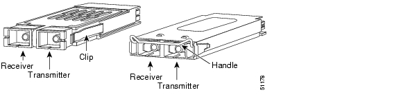
GBICs are integrated fiber optic transceivers that provide high speed serial links from a port or slot to the network. Various latching mechanisms can be utilized on the GBICs. There is no correlation between the type of latch to the model type (such as SX or LX/LH) or technology type (such as Gigabit Ethernet). See the label on the GBIC for technology type and model. One GBIC model has two clips (one on each side of the GBIC) that secure the GBIC in the slot on the Ethernet card; the other has a locking handle. Both types are shown in Figure 1.
GBIC dimensions are:
•
•
•
GBIC temperature ranges are:
•
•
•
Figure 1 GBICs with Clips (left) and with a Handle (right)
Table 2 lists specifications for available GBICs (non-DWDM/CWDM). See the "DWDM and CWDM GBICs" section for descriptions and specifications for DWDM and CWDM GBICs.
Table 2 GBIC Specifications
15454-GBIC-SX/
15454E-GBIC-SX
Short ReachGigabit Ethernet
Fibre Channel, 1 Gbps-9.5 to -4
-17 to 0
15454-GBIC-LX/LH/
15454E-GBIC-LX/LH
Long ReachGigabit Ethernet
Fibre Channel, 1 Gbps-9.5 to -3
-19 to -3
15454-GBIC-ZX/
15454E-GBIC-ZX
Extended ReachGigabit Ethernet
0 to 5
-23 to -3
15454-GBIC-xx.x1
15454E-GBIC-xx.x
DWDMGigabit Ethernet
-0 to +3
-28 to -7
15454-GBIC-xxxx 1
15454E-GBIC-xxxx
CWDMGigabit Ethernet
+1 to +5
-29 to -7
ONS-GX-2FC-MMI
Short ReachFibre Channel,
1 or 2 Gbps-9.5 to -5
-17 to 0
ONS-GX-2FC-SML
Long ReachFibre Channel,
1 or 2 Gbps-9 to -3
-18 to -3
1 Operating temperature range for a card with CWDM/DWDM GBICs installed is limited to -5 to +40 degrees Celsius. Operation with CWDM/DWDM GBICs requires R4.1 or later version G1K-4 hardware, CLEI Code WM5IRWPCAA.
GBIC Port Cabling Specifications
Table 3 provides cabling specifications for single-mode fiber (SMF) GBICs and Table 4 provides cabling specifications for multimode fiber (MMF) GBICs that you install into Ethernet cards. All GBIC ports have SC-type connectors and the minimum cable distance for all GBICs listed is 6.5 feet (2 m).
Table 3 Single-Mode Fiber GBIC Port Cabling Specifications
15454-GBIC-LX/LH
15454E-GBIC-LX/LH
Long Reach1310 nm
9 micron SMF
10 km (6.2 miles)
50.0 micron SMF
550 m (1804 ft)
62.5 micron SMF
275 m (902.2 ft)
1550 nm2
9 micron SMF
70 to 100 km3
(43.4 to 62 miles)15454-GBIC-xxxx
15454E-GBIC-xxxx
CWDMSee Table 5
9 micron SMF
100 to 120 km
(62 to 74.5 miles)15454-GBIC-xx.x
15454E-GBIC-xx.x
DWDMSee Table 6
9 micron SMF
100 to 120 km (unamplified)
(62 to 74.5 miles)Up to 300 km (amplified)
(Up to 186.4 miles)ONS-GX-2FC-SML
Long Reach1310 nm4
9 micron SMF
10 km (6.2 miles)
50.0 micron SMF
62.5 micron SMF225 m (738 ft) (with a mode conditioning patch cord for transmitter)
1 The 15454-GBIC-ZX operates on SMF optic link spans of up to 80 km in length. Link spans of up to 100 km are possible using premium SMF or dispersion shifted SMF. When shorter distances of SMF are used, it may be necessary to insert an in-line optical attenuator in the link, to avoid overloading the receiver. For fiber-optic cable spans less than 25 km, insert a 10 dB in-line optical attenuator between the fiber-optic cable plant and the receiving port on the 15454-GBIC-ZX at each end of the link. For fiber-optic cable spans equal to or greater than 25 km and less than 50 km, insert a 5 dB in-line optical attenuator between the fiber-optic cable plant and the receiving port on the 15454-GBIC-ZX at the end of the link.
2 Typical loss on a 1550 nm wavelength SMF is .3 dB/km.
3 100 km cable distance requires dispersion-shifted SMF (15454-GBIC-ZX/15454E-GBIC-ZX)
4 Typical loss on a 1310 nm wavelength SMF is .50 dB/km.
Table 4 Multimode Fiber GBIC Port Cabling Specifications
15454-GBIC-SX/
15454E-GBIC-SX
Short Reach850 nm
62.5 micron MMF
220 m (722 ft)
275 m (902 ft)
50.0 micron MMF
500 m (1640 ft)
550 m (1804 ft)
15454-GBIC-LX/LH/
15454E-GBIC-LX/LH
Long Reach1310 nm
62.5 micron MMF2
550 m (1804 ft)
50.0 micron MMF
550 m (1804 ft)
ONS-GX-2FC-MMI
Short Reach850 nm
50.0 micron MMF
550 m (1804 ft)
62.5 micron MMF
300 m (984.3 ft)
1 The numbers given for MMF refer to the core diameter. For SMF, 8.3 micron refers to the core diameter. The 9-micron and 10-micron values refer to the mode-field diameter (MFD), which is the diameter of the light-carrying portion of the fiber. This area consists of the fiber core and a small portion of the surrounding cladding. The MFD is a function of the core diameter, the wavelength of the laser, and the refractive index difference between the core and the cladding.
2 When using an LX/LH GBIC with 62.5-micron diameter MMF, you must install a mode-conditioning patch cord (CAB-GELX-625 or equivalent) between the GBIC and the MMF cable on both the transmit and receive ends of the link. The mode-conditioning patch cord is required for link distances less than 328 feet (100 m) or greater than 984 feet (300 m). The mode-conditioning patch cord prevents overdriving the receiver for short lengths of MMF and reduces differential mode delay for long lengths of MMF.
DWDM and CWDM GBICs
DWDM GBICs (15454-GBIC-xx.x and 15454E-GBIC-xx.x) and CWDM GBICs (15454-GBIC-xxxx and 15454E-GBIC-xxxx) are both wavelength division multiplexing (WDM) technologies that operate over single-mode fibers with SC connectors. Cisco CWDM GBIC technology uses a 20 nm wavelength grid and Cisco ONS 15454 DWDM GBIC technology uses a 1 nm wavelength grid. CTC displays the specific wavelengths of the installed CWDM or DWDM GBICs. DWDM wavelengths are spaced closer together and require more precise lasers than CWDM. The DWDM spectrum allows for optical signal amplification.
The ONS 15454-supported CWDM GBICs reach up to 100 to 120 km over single-mode fiber and support eight wavelengths as shown in Table 5.
The ONS 15454-supported DWDM GBICs reach up to 100 to 120 km over single-mode fiber and support 32 different wavelengths in the red and blue bands. Paired with optical amplifiers, such as the Cisco ONS 15216, the DWDM GBICs allow maximum unregenerated spans of approximately 300 km ( Table 6).
Placement of CWDM or DWDM GBICs
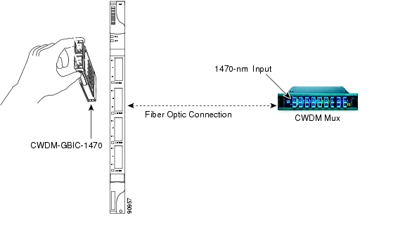
CWDM or DWDM GBICs come in set wavelengths and are not provisionable. The wavelengths are printed on each GBIC, for example, CWDM-GBIC-1490. The user must insert the specific GBIC transmitting the wavelength required to match the input of the CWDM/DWDM device for successful operation ( Figure 2). Follow your site plan or network diagram for the required wavelengths.
Figure 2 CWDM GBIC with Wavelength Appropriate for Fiber-Connected Device
The Cisco ONS 15454 Procedure Guide contains specific procedures for attaching optical fiber to GBICs and inserting GBICs into the G-Series card.
Example of CWDM or DWDM GBIC Application
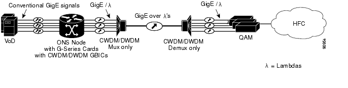
A G-Series card equipped with CWDM or DWDM GBICs supports the delivery of unprotected Gigabit Ethernet service over Metro DWDM ( Figure 3). It can be used in short-haul and long-haul applications.
Figure 3 G-Series with CWDM/DWDM GBICs in Cable Network
SFP Description and Specifications
SFPs are integrated fiber optic transceivers that provide high speed serial links from a port or slot to the network. Various latching mechanisms can be utilized on the SFPs. There is no correlation between the type of latch to the model type (such as SX or LX/LH) or technology type (such as Gigabit Ethernet). See the label on the SFP for technology type and model. One type of latch available is a mylar tab as shown in Figure 4, a second type of latch available is an actuator/button ( Figure 5), and a third type of latch is a bail clasp ( Figure 6).
SFP dimensions are:
•
•
•
SFP temperature ranges are:
•
•
•
Figure 4 Mylar Tab SFP
Figure 5 Actuator/Button SFP
Figure 6 Bail Clasp SFP
Table 7 lists specifications for available SFPs.
SFP Port Cabling Specifications
Table 8 provides cabling specifications for the SMF SFPs and Table 9 provides cabling specifications for MMF SFPs that you install into interface cards. The ports of the listed SFPs have LC-type connectors.
Table 8 Single-Mode Fiber SFP Port Cabling Specifications
ONS-SI-622-I1
Intermediate Reach1310 nm
9 micron SMF
21 km (13.05 miles)
ONS-SI-622-L1
Long Reach1310 nm
9 micron SMF
42 km (26.10 miles)
ONS-SI-622-L2
Long Reach1550 nm
9 micron SMF
85 km (52.82 miles)
ONS-SI-155-I1
Intermediate Reach1310 nm
9 micron SMF
21 km (13.05 miles)
ONS-SI-155-L1
Long Reach1310 nm
9 micron SMF
50 km (31.07 miles)
ONS-SI-155-L2
Long Reach1550 nm
9 micron SMF
100 km (62.14 miles)
15327-SFP-LC-LX
Short reach
15454-SFP-LC-LX/LH/
15454E-SFP-LC-LX/LH
Long Reach1310 nm
9 micron SMF
10 km (6.2 miles)
15454-SFP3-1-IR=
Intermediate Reach1310 nm
9 micron SMF
15 km (9.3 miles)
15454E-SFP-L.1.1=
Short Haul1310 nm
9 micron SMF
15 km (9.3 miles)
15454-SFP12-4-IR=
Intermediate Reach1310 nm
9 micron SMF
15 km (9.3 miles)
15454E-SFP-L.4.1=
Short Haul1310 nm
9 micron SMF
15 km (9.3 miles)
15454-SFP-OC48-IR=
Intermediate Reach1310 nm
9 micron SMF
15 km (9.3 miles)
ONS-SE-2G-S1=
Short Reach1310 nm
9 micron SMF
2 km (1.2 miles)
15454E-SFP-L.16.1=
Short Haul1310 nm
9 micron SMF
15 km (9.3 miles)
15454-SFP-GE+-LX=/
15454E-SFP-GE+-LX=
Long Reach1310 nm
9 micron SMF
10 km (6.2 miles) for FC 1G, FC 2G and GE
5 km (3.1 miles) for HDTVONS-SE-2G-L2
1530 nm
9 micron SMF
80 km (49.71 miles)
ONS-SE-Z1
1310 km
9 micron SMF
15 km (9.3 miles)
15600-SFP-12-4-LR2
1530 nm
9 micron SMF
80 km (49.71 miles)
ONS-SI-155-L2
1530 nm
9 micron SMF
80 km (49.71 miles)
1 Typical loss on a 1310 nm wavelength SMF is .6 dB/km.
XFP Description and Specifications
The 10 Gbps 1310 nm XFP transceiver is an integrated fiber optic transceiver that provides a high-speed serial link at the following signaling rates: 9.95 Gbps, 10.31 Gbps, 10.51 Gbps, and 10.66/10.71/11.10 Gbps which apply to 10GBASE-LR (fibre channel and Ethernet) as well as OC-192/STM-64 SONET/SDH. The XFP integrates the receiver and transmit path. The transmit side recovers and retimes the 10 Gbps serial data and passes it to a laser driver. The laser driver biases and modulates a 1310 nm DFB (distributed feed-back) laser, enabling data transmission over SMF through an LC connector. The receive side recovers and retimes the 10 Gbps optical data stream from a PIN photo detector, transimpedance amplifier and passes it to an output driver.
The XFP module uses the bail clasp latching mechanism as shown unlatched in Figure 7 and latched in Figure 8. See the label on the XFP for technology type and model.
XFP dimensions are:
•
•
•
XFP temperature ranges are:
•
•
•
Figure 7 Bail Clasp XFP (Unlatched)
Figure 8 Bail Clasp XFP (Latched)
Table 10 lists specifications for available SFPs.
XFP Port Cabling Specifications
Table 11 SIngle-Mode Fiber XFP Port Cabling Specifications
ONS-XC-10G-S1
1310 nm
SMF
10 km (6.2 miles)
GBIC, SFP and XFP Installation and Removal
This section provides installation and removal procedures for GBICs and SFPs/XFPs. Because GBICs and SFPs/XFPs are hot-swappable they can be installed and removed while the card/shelf assembly is powered and running.
Warning
Warning
Warning
Warning
Warning
Warning
Caution
Note
Removing a GBIC or SFP/XFP
Step 1
Step 2
a.
b.
Release the XFP by unlatching the bail clasp and swinging it downward.c.
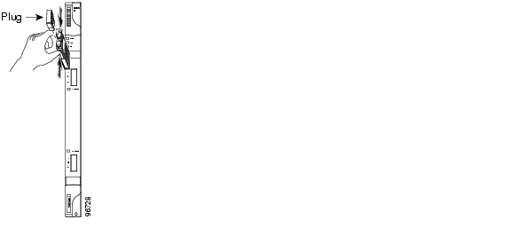
Installing a GBIC
Prior to installing a GBIC, verify that the GBIC is the correct type for your network and that you are installing compatible GBICs, for example, SX to SX or LX/LH to LX/LH.
Step 1
For a GBIC with a handle: Slide the GBIC into the slot and lock the GBIC into place by closing the handle down (it might be necessary to remove the SC-type connector protective plugs). The handle is in the correct closed position when it does not obstruct access to SC-type connector.
Note
Figure 9 GBIC installation (with clips)
Step 2
Installing an SFP/XFP
Prior to installing an SFP, verify that the SFP is the correct type for your network and that you are installing compatible SFPs, for example, SX to SX or LX/LH to LX/LH.
Step 1
For an actuator/button SFP: Slide the SFP all the way into the slot until you hear a click.
For a bail clasp SFP/XFP: Latch (flip upwards) the bail clasp before inserting into the slot then slide into the slot.
Note
Step 2
Connecting Single-Mode and Multimode Optical Fiber
Attach the appropriate optical fiber cable directly to the SC-type receptacle on the GBIC or the LC-type connector on the SFP/XFP. You can use either simplex or duplex connectors for most devices. For simplex connectors, two cables are required, one cable for transmit (Tx) and a second cable for receive (Rx). For duplex connectors, only one cable that has both Tx and Rx connectors is required.
Step 1
Step 2
Step 3
Step 4
This document is to be used in conjunction with the Cisco ONS 15454 Procedure Guide publication.
Copyright © 2004 Cisco Systems, Inc. All rights reserved.
![]()
![]()
![]()
![]()
![]()
![]()
![]()
![]()
Posted: Wed Dec 22 11:36:40 PST 2004
All contents are Copyright © 1992--2004 Cisco Systems, Inc. All rights reserved.
Important Notices and Privacy Statement.