|
|

Table Of Contents
4.2.4 Install External Ground for 230 V Supply to the ONS 15302
4.4.1 Installation in Restricted Access Locations
4.4.2 Install the ONS 15302 -48 VDC Power
4.4.3 Install External Ground for 230 V Supply to the ONS 15302
4.4.4 Install the ONS 15302 Fiber Cable
4.4.5 Install the ONS 15302 Electrical Cable
4.5.1 Factory Pre-configuration
4.6 SW Download through Local VT100 Interface
Installation
This chapter provides instructions for installing Cisco ONS 15302 system.
Note
The instructions in this section primarily address the installation of the ONS 15302, and modules supplied by Cisco Systems. When installing racks, electrical wiring, raceways, and other equipment not covered in this manual, you should follow all local, state, federal, or international (if applicable) codes and regulations.
Caution
4.1 Installation Overview
You should be thoroughly familiar with the instructions in this manual before starting any work. Use the following instructions when installing the ONS 15302.
Step 1
Step 2
Step 3
Step 4
Step 5
Step 6
4.2 Installation Planning
Based on the configuration to be installed, determine the size, number, and location of racks, as well as the ONS 15302 installation requirements. The following are unit dimensions to take into consideration when installing the ONS 15302. The ONS 15302 can be installed in 485 mm (19-in.) equipment racks, and can be adapted for 600 mm ETSI (23.6-in.) racks. The racks must be accessible from the front and rear for equipment installation.
Note
Use the following considerations when planning how to install in the rack a ONS 15302.
•
•
•
•
•
•
4.2.1 Required Items
In addition to a standard installers tool kit, the following items are also required:
•
•
•
•
•
•
•
•
•
•
4.2.2 Installation Guidelines
When installing ONS 15302 equipment into a rack, follow these guidelines:
•
•
•
•
Figure 4-1 shows the outer dimensions of the ONS 15302 system equipment.
Figure 4-1 Outer Dimensions of the ONS 15302 System
4.2.3 Install Ground to 48 V
It is vital that the ONS 15302 is properly grounded. The ONS 15302 is grounded via the 48V power connector to the rack ground, refer to "Install the ONS 15302 -48 VDC Power".
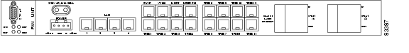
The location of the power connector on the ONS 15302 is shown in Figure 4-2.
Figure 4-2 ONS 15302 Faceplate (Connector Array)
4.2.4 Install External Ground for 230 V Supply to the ONS 15302
Note
The ONS 15302 should be grounded via the external ground connector to the rack ground.
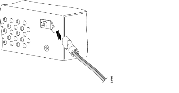
The location of the ground connector on the ONS 15302 is shown in Figure 4-3.
Figure 4-3 Ground Connector Position on the ONS 15302
Install the Ground Connector
Step 1
Step 2
Step 3
Step 4
Step 5
Step 6
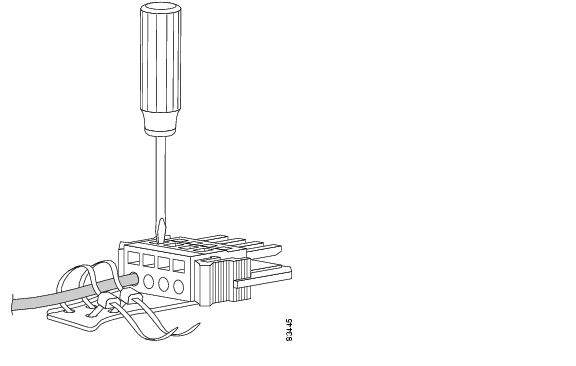
Figure 4-4 Connection of the Ground Cable with a Crimp Tool
4.2.5 Power Considerations
The ONS 15302 can be powered using a regular telecommunication power supply of -48 VDC with a VDC return. The ONS 15302 supports redundant 48 VDC power supplies but if used the two supplies should be independently powered. The ONS 15302 can also be powered using 230 VAC regular power grid.
4.3 Fiber Cleaning
Cletop cleaning cassettes (type A for SC connectors) must be used to clean the fiber connectors and adapters before installing fiber. A video inspection instrument, with optical adapters for SC connectors is also required to inspect the fiber connectors and adapters before installing fiber.
Note
Warning
Warning
Warning
Clean Fiber Connectors
Step 1
Step 2
Step 3
Step 4
Step 5
Clean Fiber Adapters
Step 1
Step 2
Step 3
Step 4
Step 5
4.4 ONS 15302 Installation
Use the following procedures to install the ONS 15302 in an equipment rack, but verify first that at least 3 RU of rack space is available.
When installing the ONS 15302, you can also use the extension brackets, included in the ONS 15302 accessory kit, to convert a 485-mm (19-inch) rack to a 600-mm (23.6-inch) rack.
Note
Caution
Mount the ONS 15302 in an Equipment Rack
Step 1
Step 2
Step 3
Step 4
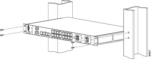
Figure 4-5 Install the ONS 15302 with the Connector Array in Front in a 19-in. Rack
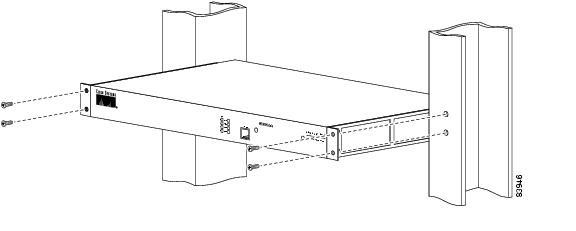
Figure 4-6 Install the ONS 15302 with the WAN Module in Front in a 19-in. Rack
Mount the ONS 15302 in an Equipment Rack Using Extension Brackets
The ONS 15302 can be installed in a 600-mm (23.6-in.) rack using the extension brackets. You need two 1 RU extension brackets for this procedure.
Step 1
Step 2
Step 3
Step 4
4.4.1 Installation in Restricted Access Locations
The ONS 15302 can be installed in a restricted access location (RAL) or outside of an RAL.
4.4.1.1 Definitions
Restricted Access Location
A restricted access location is a site location for equipment where both of the following paragraphs apply:
•
•
SELV Circuits
Safety Extra-Low Voltage (SELV) circuits are ports that have maximum DC working voltage level less than 60 V (42.4 VAC). In addition, the ports must not be connected to telecommunication networks as defined in EN 60950 (see CEI/ IEC 60950-1 2001-10, standard clause 1.2.13.8).
In practice, the electrical cables shall not exit the building. In addition, the electrical cables shall connect to equipment that meets one of the following requirements:
•
•
•
Telecommunication Network
A telecommunication network is a metallically terminated transmission medium intended for communication between equipment that might be located in separate buildings, excluding:
•
•
•
TNV Circuit
A TNV circuit in the equipment to which the accessible area of contact is limited. A TNV circuit is so designed and protected that, under normal operating conditions and single fault conditions (see CEI/IEC 60950-1 2001-10, standard clause 1.4.14), the voltages do not exceed specified limit values.
4.4.1.2 Installation in Restricted Access Location
After installation in a RAL, such as in a telecommunications center, the ONS 15302 must be properly installed in a rack with brackets or in other ways properly connected to a safety ground. The ONS 15302 48-VDC power must not be powered from a source external to the RAL. The E1 interface used should be limited to SELV.
4.4.1.3 Installation Outside of a Restricted Access Location
After installation in a non-RAL location, the ONS 15302 48-V power and all communication ports used must be connected to SELV circuits, for example, a port on a personal computer or 10/100-Mbit Ethernet hub/router or other information technology (IT) equipment. The 48-VDC power must not exceed 60 VDC, and must be powered from a certified external power supply unit (PSU) or a battery unit (with no connection to -48 V telecommunications voltage).
The optical ports and 230-VAC power plug have no limitations regarding safety recommendations.
4.4.2 Install the ONS 15302 -48 VDC Power
The following procedure explains how to install ONS 15302 power connections.
Connect the ONS 15302 A-side and B-side Power Connections to the PDP
Warning
Warning
Caution
Step 1
Step 2
Step 3
Step 4
Step 5
Step 6
Step 7
Note
Note
Figure 4-7 Connect the Wire to the Connector
Step 8
Step 9
Step 10
Step 11
Step 12
Step 13
Note
Step 14
Step 15
Step 16
Note
4.4.3 Install External Ground for 230 V Supply to the ONS 15302
The following procedure explains how to install ONS 15302 power connections.
Caution
Connect the ONS 15302 to normal AC Outlet
Step 1
Step 2
Note
4.4.4 Install the ONS 15302 Fiber Cable
Caution
To install fiber-optic cables in the ONS 15302, connect a fiber cable with SC connector type to the transmit and receive ports of the transmission system. On a the ONS 15302 module, the transmit and receive ports are located at the connector array of the unit. The receive port is named STM-1 IN and the transmit port is named STM-1 OUT.
Cisco recommends that you label the transmit and receive fiber (before installation) to and from the optical transmission system at each end of the fiber span to avoid confusion with cables that are similar in appearance.
Warning
Warning
Warning
Connect the Fiber Cable
Step 1
Step 2
Step 3
Step 4
Step 5
4.4.5 Install the ONS 15302 Electrical Cable
Caution
To install electrical connection cables in the ONS 15302, connect the electrical cable with the corresponding ports of the transmission system. On the ONS 15302 module, the electrical ports are located at the connector array of the system only the VT100 (CLI Port) is located on both sides of the system. All electrical cables are equipped with RJ-45 connectors. The alarm cable is equipped with a DS-9 connector. Cisco recommends that you label the electrical cable at each end before installation to avoid confusion with cables that are similar in appearance.
Caution
Connect the Electrical Cables with RJ-45 Connector
Step 1
Step 2
Step 3
Connect the Alarm Cable
Step 1
Step 2
Step 3
4.5 Initial Configuration
By following the guides below you should be able to do the most important configurations of ONS 15302.
4.5.1 Factory Pre-configuration
The ONS 15302 is a flexible product with many possible network applications and it is delivered from the factory with the following pre-configured settings. The Ethernet ports 1 to 5 are members of VLAN 1, the aggregate (STM-1) is enabled and one VC-12 container is allocated to the Ethernet WAN port number 5. In addition an entry in the SNMP community table is pre-configured so that when an IP address is assigned. This configuration is present, regardless of whether the WAN module is inserted or not.
Note
Follow the steps in this chapter to perform initial configuration of ONS 15302. Please note that the most important tasks involved in configuration of ONS 15302 are:
•
•
•
•
•
•
•
4.5.1.1 Connection and Password
For connection to the ONS 15302 different passwords are needed.
1.
•
•
2.
•
•
•
Note
4.5.1.2 Assign an IP Address to the ONS 15302
The ONS 15302 supports remote management solutions by the means of Telnet, SNMP, and through an Internet browser (Netscape or Microsoft Internet Explorer). Several advanced connectivity options are available with the ONS 15302. This document describes the simplest method—direct connection through the MNGT port.
To achieve connectivity for remote management solutions, you must first assign an IP address, subnet mask, and, if required, a default gateway address, as shown in Example 4-1.
Example 4-1 Assigning an IP Address
ONSCLI\Device\Management-Configuration\Management-Mode MODE=ipManagementPortPress Enter
Change management configuration, are you sure? (y/n)Press y, then Enter
MODE: IP-Management-PortONSCLI\Device\Management-Configuration\Management-Mode\CustomizeONSCLI\Device\Management-Configuration\Custom\Management-Port\IP-Configuration IP-ADDRESS=10.0.0.1 SUBNET-MASK=255.255.255.0 DEFAULT-GATEWAY=10.0.0.254Press Enter
IP-ADDRESS: 10.0.0.1SUBNET-MASK: 255.255.255.0DEFAULT-GATEWAY: 10.0.0.2544.5.1.3 Select Synchronization Source
There are several alternatives for synchronization of the ONS 15302. You can choose whether to receive synchronization from a local oscillator, from one of the tributaries, from the aggregate port, or through the dedicated SYNC port.
By default, the synchronization source is a local oscillator, but if, for example, the ONS 15302 interfaces an SDH node on the optical STM-1 interface, you must change the synchronization source to aggregate. To do this, use the command shown in Example 4-2.
Example 4-2 Selecting the Synchronization Source
ONSCLI>Device\sync-source admin-source=aggr1Press Enter
ADMIN-SOURCE: aggr1OPERATIONAL-SOURCE: Holdover4.5.1.4 Configure Ethernet WAN Bandwidth
Note
One of the many benefits of the ONS 15302 is that you can choose between all 63 of the VC-12 containers available in the STM-1 frame (limited to 50 VC-12 containers for the Ethernet WAN ports). Forty-seven VC-12 containers are sufficient for operating at 100 MBits/s (Mbps).
The VC-12 containers needed to achieve the desired bandwidth must be selected in the same order at both ends of the link. In a back-to-back configuration using two ONS 15302s, the KLM-scheme (the VC-12 mapping scheme in a VC-4 container) used must be identical. In a larger network, where the VC-12s might be cross-connected, only the sequence must be identical.
To simplify the allocation of bandwidth, the number of VC-12 containers needed can be entered together with the desired sort-mode. The VC-12s can be sorted according to ITU-T G.707 or in Lexicographic-order. The default sort-mode is Lexicographic-order.
The following example shows how bandwidth can easily be allocated for the Ethernet WAN port by selecting a number of VC-12 containers.
Step 1
ONSCLI>Ports\Ethernet-Port-Properties\WAN-Port(s)\?Press Enter
*** current menu path:<root>PortsEthernet-Port-PropertiesWAN-Port(s)*** valid commands:General: WAN port general settingsAdd-VC12-channel: Add a VC12 to WAN portEdit-VC12-channel: Modify Admin Status of a VC12Remove-VC12-channel: Remove a VC12 from WAN port(always the last)Status: Device statusFree: List of free VC12Used: List of used VC12Exit: Exit from ONSCLIStep 2
ONSCLI>...\WAN-Port(s)\generalPress Enter
WAN-PORT: 5OPER-CAPACITY: 0. Mbps.OPER-VC12-NBR: 0ADMIN-CAPACITY: 0. Mbps.ADMIN-VC12-NBR: 0PATH-TRACE: disabledEXPECTED-TI: <Path-trace J2>HEX-EXPECTED-TI: 3C,50,61,74,68,2D,74,72,61,63,65,20,4A,32,3ETRANSMIT-TI: <Path-trace J2>HEX-TRANSMIT-TI: 3C,50,61,74,68,2D,74,72,61,63,65,20,4A,32,3ERECEIVED-TI:HEX-RECEIVED-TI: 00,00,00,00,00,00,00,00,00,00,00,00,00,00,00CHANNEL-TI: 0----------------------------------------------KLM WAN-CHANNEL ADMIN-STATUS OPER-STATUS----------------------------------------------KLM table empty.Step 3
ONSCLI>...\WAN-Port(s)\Add-VC12-channel ?Press Enter
Usage:Add-VC12-channelWAN-PORT=<integer value 5:8> (Only port 5 if WAN-module not present)[KLM=<K.L.M - integer value 1:3.integer value 1:7.integer value 1:3>] (Optional starting point if desirable to add multiple VC-12 containers to a WAN-port)[ADMIN-STATUS=<enabled|disabled>] (Optional, by default enabled)[NUMBER-TO-ADD=<integer value 1:50>] (Optional, if desirable to simplify allocation of multiple VC-12 containers)[SORT-MODE=<LEX|G707>] (Optional, by default the "lexigraphic order")Configure the needed number of VC-12 containers to a selected WAN port, as shown in the following example:ONSCLI>...\WAN-Port(s)\Add-VC12-channel wan-port=5 klm=1.1.1 admin-status=enabled number-to-add=10 sort-mode=g707Press Enter
Adding klm 1.1.1 okAdding klm 2.1.1 okAdding klm 3.1.1 okAdding klm 1.2.1 okAdding klm 2.2.1 okAdding klm 3.2.1 okAdding klm 1.3.1 okAdding klm 2.3.1 okAdding klm 3.3.1 okAdding klm 1.4.1 okWAN-PORT: 5OPER-CAPACITY: 0. Mbps.OPER-VC12-NBR: 0ADMIN-CAPACITY: 21.60 Mbps.ADMIN-VC12-NBR: 10PATH-TRACE: disabledEXPECTED-TI: <Path-trace J2>HEX-EXPECTED-TI: 3C,50,61,74,68,2D,74,72,61,63,65,20,4A,32,3ETRANSMIT-TI: <Path-trace J2>HEX-TRANSMIT-TI: 3C,50,61,74,68,2D,74,72,61,63,65,20,4A,32,3ERECEIVED-TI:HEX-RECEIVED-TI: 00,00,00,00,00,00,00,00,00,00,00,00,00,00,00CHANNEL-TI: 0----------------------------------------------KLM WAN-CHANNEL ADMIN-STATUS OPER-STATUS----------------------------------------------1.1.1 1 enabled down2.1.1 2 enabled down3.1.1 3 enabled down1.2.1 4 enabled down2.2.1 5 enabled down3.2.1 6 enabled down1.3.1 7 enabled down2.3.1 8 enabled down--- More (y/n)? y "ENTER"3.3.1 9 enabled down1.4.1 10 enabled downONSCLI>...\WAN-Port(s)\4.5.1.5 Assign a VC-12 Container and Activate a 2 MBit/s (Mbps) Tributary Port
The procedure for assigning a VC-12 container to a tributary port on the ONS 15302 is similar to allocation of bandwidth to an Ethernet WAN port. The same flexibility is maintained for the selection of VC-12 containers.
Use the following procedure to configure and activate a tributary port on the ONS 15302:
Step 1
ONSCLI>Ports\TRIB-Ports\Assign-VC12-Channel ?Usage:Assign-VC12-ChannelTRIB-PORT=<integer value 1:12> (Select the Trib-port you would like to assign a VC-12 container. If desirable to assign multiple Trib-ports this will be the starting point)[KLM=<K.L.M - integer value 1:3.integer value 1:7.integer value 1:3>] (Optional, if a specific KLM reference is desirable. When assigning multiple Trib-ports simultaneously, this will be the staring point in the mapping scheme.)[NUMBER-TO-ADD=<integer value 1:12>] (Optional, desirable number of Trib-ports in multiple assignment)[SORT-MODE=<LEX|G707>] (Optional, by default the "lexigraphic order")ONSCLI>...\TRIB-Ports\assign-vc12-channel trib-port=1 klm=3.7.3Press Enter
----------------------TRIB-PORT KLM----------------------1 3.7.3Step 2
ONSCLI>...\TRIB-Ports\general ?Press Enter
Usage:General[TRIB-PORT=<integer value 1:12>] (Select desired Trib-port)[DESCRIPTION=<string[0:64]>] (Optional)[ADMINISTRATIVE-STATUS=<enable|disable>] (Select enable)[MODE=<TRA|PRA>] (Optional, default transparent (TRA) acc. to G.703)[LOOP-MODE=<NONE|LL2|LL3>] (Optional, for tests)[PATH-TRACE=<enabled|disabled>] (Optional)[EXPECTED-TI=<string[1:15]>] (Optional)[TRANSMIT-TI=<string[1:15]>] (Optional)ONSCLI>...\TRIB-Ports\general trib-port=1 description=qrg administrative-status=enable mode=praPress Enter
TRIB-PORT: 1DESCRIPTION: qrgADMINISTRATIVE-STATUS: enableOPERATIONAL-STATUS: downMODE: PRAKLM: 3.7.3LOOP-MODE: NONEPATH-TRACE: disabledEXPECTED-TI: <Path-trace J2>HEX-EXPECTED-TI: 3C,50,61,74,68,2D,74,72,61,63,65,20,4A,32,3ETRANSMIT-TI: <Path-trace J2>HEX-TRANSMIT-TI: 3C,50,61,74,68,2D,74,72,61,63,65,20,4A,32,3ERECEIVED-TI:HEX-RECEIVED-TI: 00,00,00,00,00,00,00,00,00,00,00,00,00,00,00ONSCLI>...\TRIB-Ports\4.5.1.6 Define SNMPv1 Community
The factory pre-configured SNMPv1 community is shown in Example 4-3.
Example 4-3 Factory Pre-configured SNMPv1 Community
ONSCLI>Security\Community-Table\ShowPress Enter
Manager: 0.0.0.0Community: publicAccess: superTraps: disableThis is an unsecure community that enables all managers to access the device with the community string public, regardless of the IP address of the SNMP manager.
To add your own community string, use the following command:
ONSCLI>Security\Community-Table\Add MANAGER=10.0.0.20 COMMUNITY=admin ACCESS=super
TRAPS=enable
Press Enter
4.5.1.7 Erase a Community String
To remove a community string the following command can be used:
ONSCLI>Security\Community-Table\remove manager=0.0.0.0 community=publicPress Enter
4.6 SW Download through Local VT100 Interface
The software is loaded using a PC connected directly to the ONS 15302 via the VT100 port. You must be on site with the ONS 15302 to install the software, you can not complete the installation remotely. The file is loaded using the Xmodem protocol. Booting the system triggers local software download. Ethernet traffic is lost during the software load process. Please secure the traffic on 2 MBit/s (Mbps) tributaries.
Please follow the steps below for a successful download operation.
Step 1
Step 2
Step 3
Step 4
Figure 4-8 ONS 15302 Software Download Startmenu
Note
Step 5
Choose the number for your selectionFigure 4-9 Select a Baud Rate
Step 6
Step 7
Step 8
Table 4-1 EIA/TIA 232 Interface Parameter
Bits per second
115200
Data bits
8
Parity
None
Stop bits
1
Flow control
Hardware
Step 9
Please download program using XMODEM.$$$$The device is now ready to receive the new software (firmware).
Step 10
a.
b.
Figure 4-10 Hyper Terminal Window
Step 11
The correct filename appears, otherwise press Browse and search for the right filename.
Choose Protocol Xmodem.
Press Send.
Figure 4-11 Send File Menu
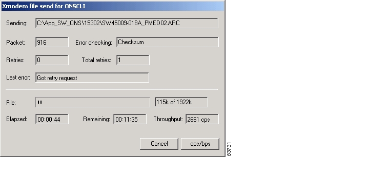
The download is now started and you can monitor the download process in the Remaining field, Figure 4-12.
Figure 4-12 Download Response Menu
When the download has finished, the device will immediately start to write to flash and update its registry and automatically reboot. The total time for the download operation is approximately 10 minutes.
Step 12
Step 13
ONSCLI>Device\Inventory
![]()
![]()
![]()
![]()
![]()
![]()
![]()
![]()
Posted: Tue Jan 8 08:19:02 PST 2008
All contents are Copyright © 1992--2008 Cisco Systems, Inc. All rights reserved.
Important Notices and Privacy Statement.