|
|

Table Of Contents
6.3 Light Emitting Diodes (LEDs)
6.4 Optical Aggregate Line Interface
6.6 LAN Ports and Management Port
Technical Specifications
This chapter provides Technical Specifications of the Cisco ONS 15302.
6.1 Mechanical Overview
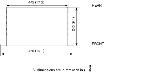
The equipment is provided as a subrack suitable for mounting within a 485mm (19-in.) and 600mm (23.6-in) equipment cabinet.
Figure 6-1 shows the outer dimensions of the ONS 15302 system equipment.
Figure 6-1 Outer Dimensions of the ONS 15302 System
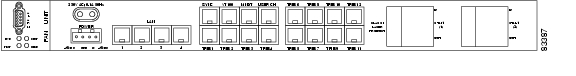
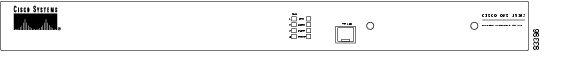
Figure 6-2 and Figure 6-3 display the two different views of the ONS 15302 with the different LEDs and connectors.
Figure 6-2 View of the ONS 15302 with the Connector Array in Front
Figure 6-3 View of the ONS 15302 with the WAN Module in Front
6.2 Interfaces
The table below show the relationship between the type of interface and the logical names use in this document.
6.3 Light Emitting Diodes (LEDs)
The LED indicators are used to visualize the ONS 15302 status:
6.4 Optical Aggregate Line Interface
The ONS 15302 aggregate line interface is bidirectional with a transmit (Tx) and a receive (Rx) direction. The two fibre variant is a short haul (SH), ITU-T Rec. G.957 S-1.1 compliant variant. The transmission cable can be either Single Mode (SM) or Multi Mode fibre (MM) type.
ONS 15302 is also available in protected variants with duplicated optical interfaces and protection switching logic to maintain traffic in case of fibre faults.
The optical interfaces are located at connector array side and equipped with SC connectors.
Parameters
Note
The definitions of optical parameters and reference points S and R refer to ITU-T G.957. Reference point S means transmit direction while R is the receive direction of the fibre.
Factory testing to Power Budget: Mean Launched Power adjusted to -10 dBm. Receiver sensitivity test: Max. signal level -32 dBm at R point at BER < 1 in 10 exp -10. Initial equipment margin: >3 dB.
Table 6-7 Typical Link Spans for ONS 15302
Short-Haul
SM
34 km
80 km
34 km
Short-Haul
MM
13 km
9 km
9 km
Jitter on the Tx optical output signal is lower than the values specified in ITU-T Rec. G.813, ( Table 6-8).
.
Table 6-8 Optical Output Jitter Requirements as given in ITU-T Rec. G.813.
500 Hz to 1.3 MHz
0.50 Uipp
65 kHz to 1.3 MHz
0.10 Uipp
The input aggregate port tolerates the input jitter and wander specified in ITU-T Rec. G.825, ( Table 6-9). This applies in the whole operating optical range of the receiver.
6.5 Tributary Ports
Connectors
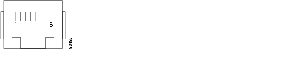
The connectors are RJ-45 connectors, with the following pinout
Table 6-10 Pinout Tributary Interface
1
RxD+
2
RxD-
3
GND
4
TxD+
5
TxD-
6
Screen, (the outer screen is always connected to ground)
7
NC
8
NC
Figure 6-4 Tributary 120 Ohm Interface Connector
Parameters
The next tables displays the parameters of the tributary port
Table 6-11 Tributary input jitter parameters is compliant to the ITU-T G.823 02/00 table 16 requirements.
Table 6-11 Tributary Input Jitter Parameters
20 Hz to 2.4 kHz
1.5 Uipp
2.4 kHz to 18 kHz
Decaying, slope equal to 20 dB/decade
18 kHz to 100 kHz
0.2 Uipp
Table 6-12 Tributary input reflection loss is complaint to ITU-T G.703
Table 6-12 Tributary Input Reflection Loss
51 kHz to 102 kHz
12 dB
102 kHz to 2048 kHz
18 dB
2048 kHz to 3072 kHz
14 dB
The requirements for output jitter in the absence of input jitter and pointer movements are shown in Table 6-13. The output jitter is complaint to requirements ITU-T G.783.
Table 6-13 Tributary Output Jitter without Pointer Movements
20 Hz to 100 kHz
< 0.25 UI
700 Hz to 100 kHz
< 0.075 UI
The requirements for output jitter in the absence of input jitter but with pointer movements are shown in Table 6-14. The output jitter is complaint to requirements ITU-T G.783
Table 6-14 Tributary Output Jitter with Pointer Movements
20 Hz to 100 kHz
< 0.4 UI
700 Hz to 100 kHz
< 0.075 UI
6.6 LAN Ports and Management Port
Connectors
The connectors are RJ-45 connectors, with the following pinout:
Figure 6-5 LAN Ports and Management Connector
Note
6.7 Alarm Interface
Connectors
The alarm interface connector is a DS-9 connector, with the following pinout
:
Parameters
6.8 Synchronization Port
ONS 15302 has one 2048 kHz synchronization output port and input port.
Connectors
Both input and output is provided on 8 pin RJ-45 connector, with the following pinout
:
Table 6-19 Pinout Synchronization Port
1
Sync input +
2
Sync input -
3
GND
4
Sync output +
5
Sync output -
6
Screen (the outer screen is always connected to ground)
7
NC
8
NC
Figure 6-6 Synchronization Connector
Parameters
Table 6-20 Synchronization Input Jitter Parameters
20 Hz to 2.4 kHz
1.5 Uipp
2.4 kHz to 18 kHz
Decaying, slope equal to 20 dB/decade
18 kHz to 100 kHz
0.2 Uipp
Table 6-21 Synchronization Input Reflection Loss Parameters
2048 kHz
15 dB
Table 6-22 Synchronization Output Jitter Parameters
20 Hz to 100 kHz
< 0.05UI
6.9 ONSCLI Port
The ONSCLI Port is accessible from both side of the unit by means of two parallel connectors.
Connectors
The EIA/TIA 232 interface for ONS 15302 is provided using a RJ-45 connector, with the following pinout Table 6-13.
Table 6-23 Pinout CLI Connector
1
GND
2
TxD
3
RxD
4
DB_TxD (are only used for debug purposes)
5
NC
6
RTS
7
DB_RxD (are only used for debug purposes)
8
NC
Figure 6-7 ONSCLI Port Connector
Table 6-24 CLI Connector Pinout (RJ-45 to DS-9)
Pin 1
GND
Pin 5
NC
Pin 2
Tx
Pin 2
Rx
Pin 3
Rx
Pin 3
Tx
Pin 4
NC
Pin 5
NC
Pin 6
CTS
Pin 8
CTS
Pin 7
NC
Pin 8
RTS
Pin7
RTS
Pin 4 and 7 are only used for debug purposes.
Parameters
The interface is running at a data rate of 19.200 baud.
6.10 Power Supply
ONS 15302 supports two different power supplies:
•
•
Connectors
The -48V DC supply input on the ONS 15302 is provided via a 4 pin power connector, with the following pinout Table 6-25.
Table 6-25 Pinout Power Supply Connector
1
-48V (supply 1)
2
GND
3
0V (-48V return)
4
-48V (Supply 2)
The 230V mains supply input on the ONS 15302 is provided via a standard connector according to EN60320.
Parameters
The -48V DC input and the 230V mains input are according to the specifications given in the table below
Table 6-26 Power Supply Parameters
Power dissipation
Less than 40W
Fuse
1.5A
Battery voltage range
-36 to -72 V DC
Mains voltage
230V AC +/- 10%
6.11 User Channel
A user channel is provided for transportation of general data. The port is balanced V.11 and support synchronous 64 kBit/s or asynchronous 19.2 kBit/s by configuration.
Connectors
The user channel interface for ONS 15302 is provided using a RJ-45 connector, with the following pinout Table 6-27
Table 6-27 Pinout User Channel Connector
1
TxD+
2
TxD-
3
RxD+
4
TxCLK-
5
TxCLK+
6
RxD-
7
RxCLK+
8
RxCLK-
Figure 6-8 User Channel Port Connector
6.12 Fan Unit
The main feature of the fan unit is to ventilate the 19"/ 1U cabinet used for ONS 15302. The fan unit is a plug in device consisting of a circuit board with two fans. The air is sucked in via two circular openings in the left sidewall, and emerges via holes in the right side cabinet wall. Two fans are used to improve reliability and give a lifetime of 10 years for this module.
Note
Parameters
Fan operation is shown in the table below. Threshold temperatures are approximate and depend on ventilation conditions.
Note
.
Note
6.13 Reliability
The overall error ratio of a tributary channel is better than 10 exp -10.
According to MIL-HDBK-217F with a correction factor adjustment related to the following conditions:
•
•
•
.
Table 6-29 Reliability
ONS 15302 non-redundant optics
40
ONS 15302 redundant optics
47
![]()
![]()
![]()
![]()
![]()
![]()
![]()
![]()
Posted: Tue Jan 8 08:28:15 PST 2008
All contents are Copyright © 1992--2008 Cisco Systems, Inc. All rights reserved.
Important Notices and Privacy Statement.