cc/td/doc/product/ong/15216/flexlayr
hometocprevnextglossaryfeedbacksearchhelp
PDF

Table Of Contents

Installation

2.1  Overview

2.2  Install the ONS 15216

2.3  Fiber Optic Connector Cleaning and Maintenance

2.3.1  Customer Supplied Cleaning Materials

2.3.2  Clean the Bulkhead Mating Adapters

2.3.3  Clean Fiber-Optic Cable Connectors

2.4  Install and Route Fiber-Optic Cables


Installation


2.1  Overview

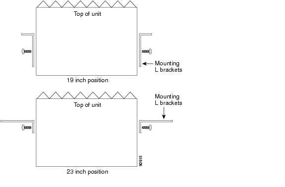
The ONS 15216 can be installed in a standard 19- or 23-inch equipment rack. Each assembly includes reversible mounting brackets that you can rotate to fit either rack size. The unit ships with the mounting brackets in the 19-inch position. Figure 2-1 shows the top view of a unit with the mounting brackets in both positions.

Figure 2-1 ONS 15216 Reversible Mounting Brackets

Four rack-mounting screws are included with each ONS 15216. Because the ONS 15216 is a passive device, no power cabling or connections are necessary. The unit can be installed anywhere in the rack (in other words, above or below the DWDM generating equipment), according to local site practice.

2.2  Install the ONS 15216

The FlexLayer shelf assembly is 1 RU high and can be mounted in a 19- or 23-inch rack (2-way mounting brackets). The shelf assembly is made to house four Add/Drop or Splitter/Combiner FlexLayer modules or two VOA FlexLayer modules. Frame grounding terminals and a fiber management tray are also provided. Figure 2-2 shows the FlexLayer shelf assembly and how it supports FlexLayer modules.

Figure 2-2 ONS 15216 FlexLayer Shelf Assembly


Step 1 Set the mounting brackets to the 19- or 23-inch position, depending on the rack you are using.


Note Remember that the units are shipped with the mounting brackets in the 19-inch position. See Figure 2-1 for mounting bracket positioning.


Step 2 Secure the unit to the rack using the three mounting screws provided.

Step 3 As appropriate, connect the fibers according to the fiber connection drawings referenced in the port layouts shown in Figure 4-4, Figure 4-7, Figure 4-8, Figure 4-17, Figure 4-18, Figure 4-20, Figure 4-21, Figure 4-23, Figure 4-24, Figure 4-29 and Figure 4-32.


2.3  Fiber Optic Connector Cleaning and Maintenance

Connector cleaning is required to maintain the performance of fiber-optic circuits. It is important that both the LC/UPC connector at the end of the fiber-optic cable and the mating bulkhead adapter on the front panel of the ONS 15216 are clean before the connection is made.


Warning To prevent serious eye damage, never look directly into a fiber optic cable connector or mating adapter. Never assume laser power is turned off or the fiber is disconnected at the other end.


Warning Always handle, use, and dispose of chemicals and other cleaning materials in accordance with manufacturer's instructions.


Note Before installing the fiber-optic cable, always perform the cleaning procedure for cable connectors described in the following section. Whenever possible, inspect each connector before connecting it to the mating bulkhead adapter on the ONS 15216 front panel.


Note The LC bulkhead adapters on the ONS 15216 front panel are less likely to get dirty if they are capped when not in use. Because the procedure for a thorough cleaning of these adapters is complicated and involves opening the ONS 15216 unit, Cisco recommends that you use a commercially available cleaning kit and closely follow the instructions included with the kit. Only a simple, routine cleaning procedure for these adapters that can be easily performed by the customer is described here.


2.3.1  Customer Supplied Cleaning Materials

The following cleaning materials are recommended but are not supplied with the ONS 15216 unit:

Reagent grade ethyl alcohol in an alcohol dispenser

Lint free laboratory wipes

Clean, dry, oil-free compressed air

When cleaning a paired cable connector (bulkhead mating adapter), always clean the mating adapter first.

If properly maintained (only used with clean, defect-free fiber connectors and capped when not in use), the mating adapter should not require cleaning. However, if you suspect the adapter is dirty, clean it by blowing with clean, dry, oil-free compressed air.

2.3.2  Clean the Bulkhead Mating Adapters


Step 1 Read the manufacturer instructions to properly use the compressed air can.


Note Improper use of the compressed air may cause more contamination to the part being cleaned and defeat the purpose of cleaning the bulkhead mating adapters.


Step 2 Before blowing the adapter clean, release a short blast of compressed air to remove any dust inside the nozzle of the compressed air can.

Step 3 Blow three to four short blasts of air into the adapter housing to remove any dust.


Note Always keep unused adapter ports and fiber connectors capped with a clean dust cap.


2.3.3  Clean Fiber-Optic Cable Connectors


Step 1 Fold a clean wipe several times to get a pad of 6 to 8 layers of material.

Step 2 Remove the protective cap on the LC/UPC optical fiber cable connector.

Step 3 Dampen (but do not soak) a corner of the pad with alcohol using the alcohol dispenser.

Step 4 Firmly press the tip of the ferrule into the alcohol-moistened area of the wipe. Pinch the wipe firmly with your fingers against the ferrule and twist the ferrule to firmly wipe the ferrule. Repeat this step three times, using a clean alcohol-moistened area each time.


Note The design of the LC connector makes it difficult to clean the entire perimeter of the ferrule, because only a small portion close to the ferrule tip is accessible. Clean the tip of the ferrule and the entire accessible perimeter. Keep the fiber connector capped at all times when not in use.


Step 5 Press the ferrule tip into a clean, dry spot on the wipe and perform the pinch-and-twist procedure described in Step 4 once.

Step 6 Discard the used wipe.

Step 7 (Optional) A couple of short blasts of clean, dry oil-free compressed air should remove any tissue fragments that may have been deposited on the ferrule during cleaning.

Step 8 Whenever possible, inspect the ferrule end-face to ensure that the cleaning procedure effectively removed the dust/dirt from the ferrule and that no cleaning-induced damages are present.

Step 9 If the ferrule end-face is still dirty, repeat Steps 1 through 8.

Step 10 If the ferrule shows damages (for example, scratches or pits across the fiber core), replace the fiber patch cord with a new one equipped with a defect-free connector.

Defects on the fiber cable connector are likely to damage the mating connector inside the ONS 15216, which results in more costly repairs.

Step 11 If the ferrule end-face is clean and damage-free, place the connector into the corresponding clean mating adapter on the ONS 15216 front panel following the instructions in the next section.


2.4  Install and Route Fiber-Optic Cables


Warning Follow all directions and warning labels when working with optical fiber cables and adapters. To prevent serious eye damage, never look directly into an optical fiber cable connector or mating adapter.


Warning When connecting an optical fiber patch cord between the ONS 15216 and the optical card ports in the ONS 15454, use the electrostatic discharge wristband supplied with the ONS 15454. Plug the wristband into the ESD jack on the lower right front side of the ONS 15454.


Note Always clean all fiber connectors thoroughly before making the connection with the mating adapter. Very small particles can permanently damage the end of the mating fiber inside the ONS 15216 unit, which makes regular cleaning imperative. See the "Fiber Optic Connector Cleaning and Maintenance" section for cleaning instructions.


Note The ONS 15216 front panel features LC/UPC bulkhead adapters. Always use fiber optic cables equipped with the corresponding (LC/UPC) connector type. Using any other type of connector results in damaging the connector and/or adapter.


Step 1 Place the LC/UPC cable connector in front of the corresponding bulkhead adapter on the front panel of the ONS 15216.

Step 2 Align the keyed ridge of the cable connector with the slot in the receiving adapter.

Step 3 Gently push the cable connector into the adapter until you hear a click, indicating the latching system is engaged.

Step 4 Open the fiber guide by pulling the fiber guide locker on the appropriate side of the front panel.

Step 5 A spring-ball screw that allows the fiber guide locker to be easily opened or closed secures the top.

Step 6 Route fiber cables through the fiber guide and lock them into place using the fiber guide locker.


hometocprevnextglossaryfeedbacksearchhelp

Posted: Sun Apr 2 11:05:01 PDT 2006
All contents are Copyright © 1992--2006 Cisco Systems, Inc. All rights reserved.
Important Notices and Privacy Statement.