|
|

Table Of Contents
4.2 Eight-Channel Optical Add or Drop FlexLayer Module
4.3 Two-Channel Optical Add or Drop FlexLayer Module
4.4 Four-Band Splitter/Combiner FlexLayer Module
4.5 Optical Splitter or Coupler FlexLayer Modules
4.5.1 1:2 Splitter or 2:1 Coupler
4.5.2 1:3 Splitter or 3:1 Coupler
4.5.3 1:4 Splitter or 4:1 Coupler
4.7 Four-Channel Variable Optical Attenuator (VOA) FlexLayer Module
Hardware
4.1 Hardware Overview
This release introduces several modules that can be used to support the ONS 15216 FlexLayer Asymmetric DWDM solution. The part numbers are listed in Table 4-1.
4.2 Eight-Channel Optical Add or Drop FlexLayer Module
The Eight-Channel Add/Drop FlexLayer module is a completely passive unidirectional component that allows the insertion or the extraction of eight channels within the ONS 15216 channel plan. Four specific modules are available to cover the whole 32-channel bandwidth (see Figure 3-1 on page 3-3).
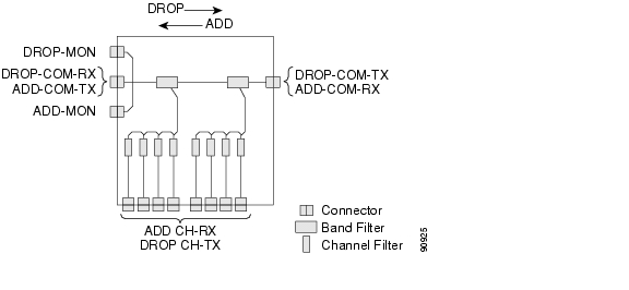
Figure 4-1 shows the unit functional block diagram. In reference to Figure 4-1, the signal flows from left to right when the unit is used as a drop site and from right to left when the unit is used as an add site.
Figure 4-1 Eight Channel Add or Drop FlexLayer Module Block Diagram
When the unit is used as a drop component, the WDM composite signal coming from the DROP-COM-RX port is filtered sequentially by a band and a channel filter and the filtered channels are dropped at the eight DROP-CH-TX ports. The remainder of the WDM composite signal is sent to the DROP-COM-TX port. A 2% tap coupler, DROP-MON, is used to monitor the input WDM composite signal.
Note
Throughout this document the following convention is used for port labeling: any input port is labeled "RX" and all the output ports are labeled "TX."
When the unit is used as an add component, the eight channels coming from the eight ADD-CH-RX parts are added to the WDM composite signal coming from the ADD-COM-RX ports. The muxed WDM composite signal is sent to the ADD-COM-TX port. A 2% tap coupler, ADD-MON, is used to monitor the muxed WDM composite signal.
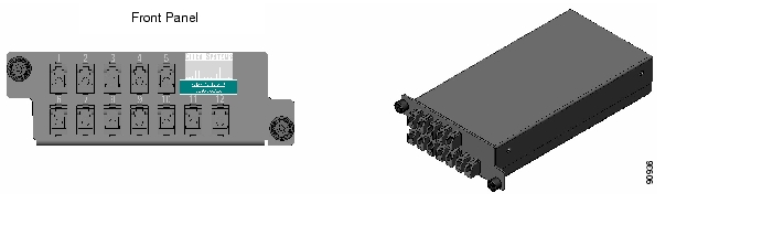
Figure 4-2 shows the physical appearance of the ONS 15216 Eight-Channel Add/Drop FlexLayer Module.
Figure 4-2 The ONS15216 Eight-Channel Add/Drop FlexLayer Module.
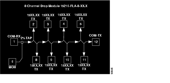
Labels are provided to show how the unit ports are mapped. It is the end user responsibility to label the unit for its intended use (drop or add component). Figure 4-3 shows how the connectors are mapped and labeled in the front panel when the component is used as a drop. The COM-RX is mapped to Port 1, the COM-TX is mapped to Port 12, and the eight dropped channel TX ports are mapped to Ports 2 to 5 and 8 to 11. The 2% tap MON port is mapped to Port 6. Port 7 is not active.
Figure 4-3 Eight Channel Drop Component Connector Mapping and Labeling
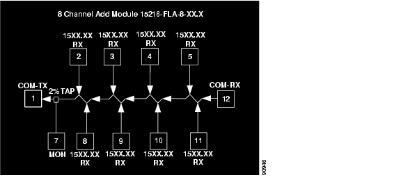
Figure 4-4 shows how the connectors are mapped and labeled in the front panel when the component is used as an add. The COM-TX is mapped to Port 1, the COM-RX is mapped to Port 12, and the added channels are mapped to the eight RX Ports 2 to 5 and 8 to 11. The 2% tap MON port is mapped to Port 7. Port 6 is not active.
Figure 4-4 Eight Channel Add Component Connector Mapping and Labeling
See "Specifications" for unit specifications.
4.3 Two-Channel Optical Add or Drop FlexLayer Module
The Two-Channel Add/Drop FlexLayer module is a completely passive unidirectional component that allows the insertion or the extraction of two channels within the ONS 15216 channel plan. Sixteen specific modules are available to cover the whole 32-channel bandwidth (see Table 3-1 on page 3-1).
Figure 4-5 shows the unit functional block diagram. In reference to Figure 4-5, the signal flows from left to right when the card is used as a drop and from right to left when the card is used as an add.
Figure 4-5 Two-Channel Add or Drop FlexLayer Module Block Diagram
When the unit is used as a drop component, the WDM composite signal coming from the DROP-COM-RX port is filtered sequentially by two filters and the filtered channels are dropped at the two DROP-CH-TX ports. The remainder of the WDM composite signal is sent to the DROP-COM-TX port. A 2% tap coupler, DROP-MON, is used to monitor the input WDM composite signal.
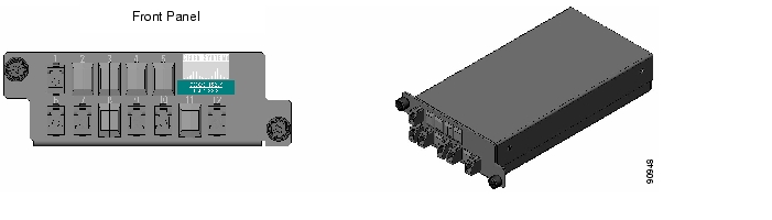
When the unit is used as an add component, the added channels coming from the two ADD-CH-RX ports are combined with the WDM composite signal coming from the ADD-COM-RX port. The muxed WDM composite signal is sent to the ADD-COM-TX port. A 2% tap coupler, ADD-MON, is used to monitor the muxed WDM composite signal. Figure 4-6 shows the physical appearance of the ONS15216 Two- Channel Add/Drop FlexLayer Module.
Figure 4-6 ONS15216 Two-Channel Optical Add/Drop FlexLayer Module
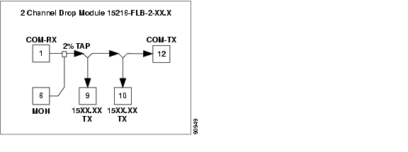
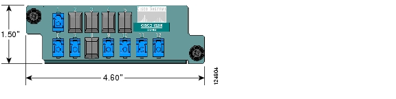
Labels are provided to show how the unit ports are mapped. It is the end user responsibility to label the unit for its intended use (drop or add component). Figure 4-7 shows how the connectors are mapped and labeled on the front panel when the component is used as a drop. The COM-RX is mapped to Port 1, the COM-TX is mapped to Port 12, and the two dropped channel TX ports are mapped to ports 9 and 10. The 2% tap MON port is mapped to Port 6. Port 7 is not active.
Figure 4-7 Two Channel Drop Component Connector Mapping and Labeling
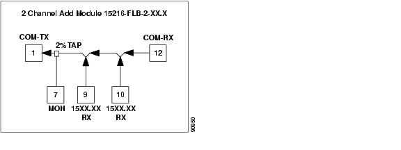
Figure 4-8 shows how the connectors are mapped and labeled in the front panel when the component is used as an add. The COM-TX is mapped to Port 1, the COM-RX is mapped to Port 12, and the added channels are mapped to the two RX Ports 9 and 10. The 2% tap MON port is mapped to Port 7. Port 6 is not active.
Figure 4-8 Two Channel Add Component Connectors' Mapping and Labeling
See "Specifications" for unit specifications.
4.4 Four-Band Splitter/Combiner FlexLayer Module
The Four-Band Splitter/Combiner (15216-SC-4B) FlexLayer module is a completely passive four band mux/demux (wavelength sensitive) module that can be used as a splitter or coupler. This card is an add-on to the Splitters/Combiner (15216-CS-x) cards of the FlexLayer product line. The functionality of the Four-Band Splitter/Combiner card is similar to the 1:4 Splitter/4:1 Combiner card (15216-CS-4), but the 15216-SC-4B client ports are wavelength selective and therefore cannot be interchanged. The advantage of this card with respect to the 15216-SC-4 is its lower insertion loss.
Figure 4-9 shows the Four-Band Splitter/Combiner (15216-CB-46) module.
Figure 4-9 SC-4B Front Panel Layout
Figure 4-10 shows the schematic block diagram of the 4-Band Splitter/Coupler FlexLayer module. In the figures below, the signal flows from bottom to right when the card is used as a coupler and from right to bottom when the card is used as splitter. When the card is used as a coupler, the individual signals enter the card from the CPL-RXBn1 ports that are coupled together through a passive star coupler to the CPL-TX port. All ports are not wavelength selective.
When the card is used as a splitter, the composite signal enters the card from the SPL-RX port and is split through a passive star coupler to the SPL-TXBn ports. All "Bn" ports are wavelength selective and show the port mapping with the bands.
Figure 4-10 4B Splitter/Coupler (15216-SC-4B) Block Diagram
Because the same card will be used as a splitter or a coupler card, different port-mapping and labeling is used for the two instances. Only one monitor is used in each of the two configurations. The different labeling is indicated with a sticker.
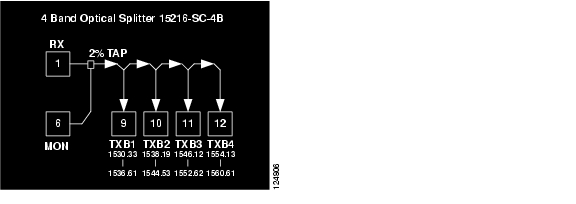
When the card is used as a splitter (see Figure 4-11), the composite RX port is mapped to Port 1, the TXB1, TXB2, TXB3, and TXB4 ports are mapped to Ports 9, 10, 11, and 12 respectively, and the monitor port is mapped to Port 6. Port 7 is not active.
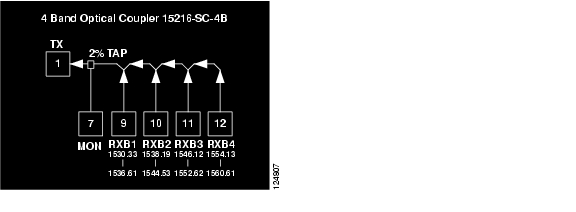
When the card is used as a coupler (see Figure 4-12), the RXB1, RXB2, RXB3, RXB4 ports are mapped to Ports 9, 10, 11, and 12 respectively, the composite TX port is mapped to Port 1, and the monitor port is mapped to Port 7. Port 6 is not active.
Figure 4-11 SC-4B Splitter Port Mapping and Labeling
Figure 4-12 SC-4B Coupler Port Mapping and Labeling
4.5 Optical Splitter or Coupler FlexLayer Modules
The 1:x Splitter/x:1 Combiner (x being 2, 3, or 4) modules are completely passive star coupler components (wavelength insensitive) that can be used as splitters or couplers. These modules can be used to couple the composite outputs (ADD-COM-TX ports) of the Optical Add/Drop FlexLayer modules or split their input signal to the composite input (DROP-COM-RX) of the Optical Add/Drop FlexLayer modules.
Figure 4-13, Figure 4-14 and Figure 4-15 show the unit block diagrams of the 1:2 Splitter/2:1 Coupler, 1:3 Splitter/3:1 Coupler, and the 1:4 Splitter/4:1 Coupler respectively. In Figure 4-13, Figure 4-14, and Figure 4-15, the signal flows from bottom to right when the component is used as a coupler and from right to bottom when the component is used as splitter.
When the module is used as a coupler, the individual signals enter the card from the CPL-RX ports and are coupled together through a passive star coupler to the CPL-TX port. All ports are not wavelength selective (that is, in the operating wavelength range).
When the module is used as a splitter, the composite signal enters the card from the SPL-RX port and is split through a passive star coupler to the SPL-TXn ports. These modules (although designed to pass wavelengths associated with the ONS15216 32-channel plan) are not selective to specific wavelengths (that is, the units do not filter wavelengths).
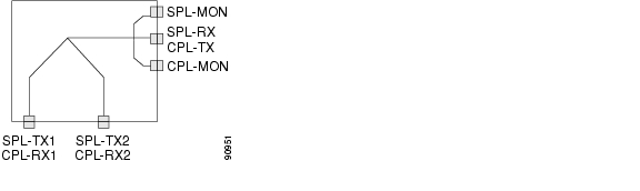
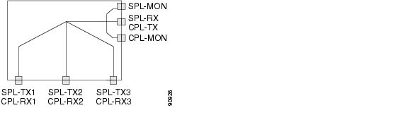
Figure 4-13 1:2 Splitter or 2:1 Coupler FlexLayer Module Block Diagram
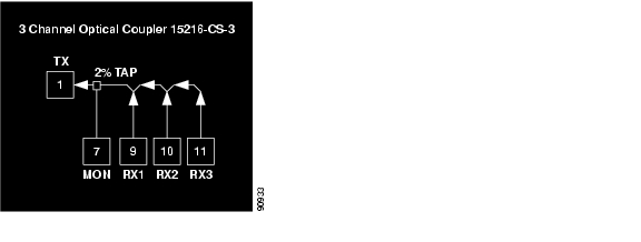
Figure 4-14 1:3 Splitter or 3:1 Coupler FlexLayer Module Block Diagram
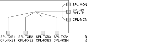
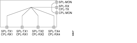
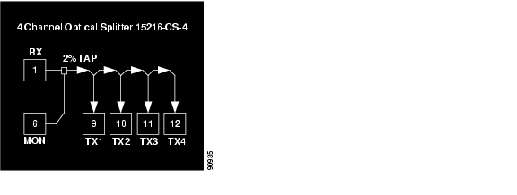
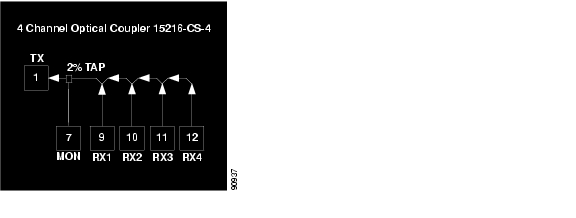
Figure 4-15 1:4 Splitter or 4:1 Coupler FlexLayer Module Block Diagram
4.5.1 1:2 Splitter or 2:1 Coupler
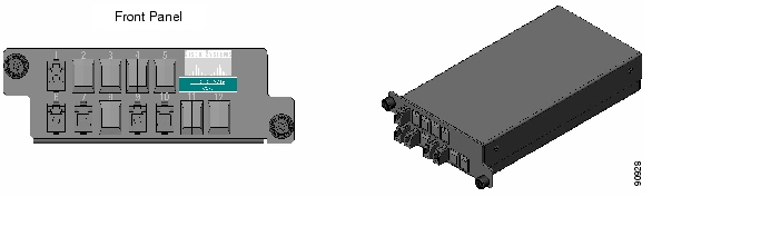
Figure 4-16 shows the ONS15216 1:2 Splitter/2:1 Coupler FlexLayer module.
Figure 4-16 ONS15216 1:2 Splitter or 2:1 Coupler FlexLayer Module
Labels are provided to show how the unit ports are mapped. It is the end user's responsibility to label the unit for its intended use (drop or add component).
Figure 4-17 shows how the module front panel ports are mapped and labeled when it is used as a splitter. The composite RX port is mapped to Port 1, the TX1 and TX2 ports are mapped to Ports 9 and 10 respectively, and the 2% tap monitor port is mapped to Port 6. Port 7 is not active.
Figure 4-17 1:2 Splitter Component Connectors' Mapping and Labeling
Figure 4-18 shows how the module front panel ports are mapped and labeled when the it is used as a coupler. The RX1 and RX2 ports are mapped to Ports 9 and 10 respectively, the composite TX port is mapped to Port 1, and the 2% tap monitor port is mapped to Port 7. Port 6 is not active.
Figure 4-18 2:1 Coupler Component Connector Mapping and Labeling
4.5.2 1:3 Splitter or 3:1 Coupler
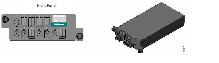
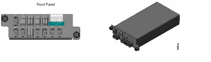
Figure 4-19 shows the ONS15216 1:3 Splitter/3:1 Coupler FlexLayer Module.
Figure 4-19 ONS15216 1:3 Splitter or 3:1 Coupler FlexLayer Module
Labels are provided to show how the unit ports are mapped. It is the end user's responsibility to label the unit for its intended use (drop or add component).
Figure 4-20 shows how the module front panel ports are mapped and labeled when it is used as a splitter. The composite RX port is mapped to Port 1, the TX1, TX2, and TX3 ports are mapped to Ports 9, 10, and 11 respectively, and the 2% tap monitor port is mapped to Port 6. Port 7 is not active.
Figure 4-20 1:3 Splitter Component Connectors' Mapping and Labeling
Figure 4-21 shows how the module front panel ports are mapped and labeled when it is used as a coupler. The RX1, RX2, RX3 ports are mapped to Ports 9, 10, and 11 respectively, the composite TX port is mapped to Port 1, and the 2% tap monitor port is mapped to Port 7. Port 6 is not active.
Figure 4-21 3:1 Coupler Component Connector Mapping and Labeling
4.5.3 1:4 Splitter or 4:1 Coupler
Figure 4-22 shows the ONS 15216 1:4 Splitter/4:1 Coupler FlexLayer Module.
Figure 4-22 ONS15216 1:4 Splitter or 4:1 Coupler FlexLayer Module
Labels are provided to show how the unit ports are mapped. It is the end user's responsibility to label the unit for its intended use (drop or add component).
Figure 4-23 shows how the module front panel ports are mapped and labeled when it is used as a splitter. The composite RX port is mapped to Port 1, the TX1, TX2, TX3, and TX4 ports are mapped to Ports 9, 10, 11, and 12 respectively, and the 2% tap monitor port is mapped to Port 6. Port 7 is not active.
Figure 4-23 1:4 Splitter Component Connector Mapping and Labeling
Figure 4-24 shows how the module front panel ports are mapped and labeled when it is used as a coupler. The RX1, RX2, RX3, RX4 ports are mapped to Ports 9, 10, 11, and 12 respectively, the composite TX port is mapped to Port 1, and the 2% tap monitor port is mapped to Port 7. Port 6 is not active.
Figure 4-24 4:1 Coupler Component Connector Mapping and Labeling
4.6 Y-Cable Protection Module
The Y-cable protection module is a bidirectional module. It is equipped with a passive star coupler that is used as a splitter and a passive star coupler that is used as a coupler.
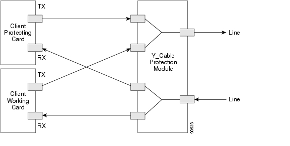
The purpose of this module is to provide Y-Cable protection for transponder cards such as the ONS15454 multirate and 10G transponders (see Figure 4-25). There are two versions of this unit, one for multimode applications (CS-MM-Y) and one for single-mode applications (CS-SM-Y).
Figure 4-25 Typical Y-Cable Protection Module Configuration
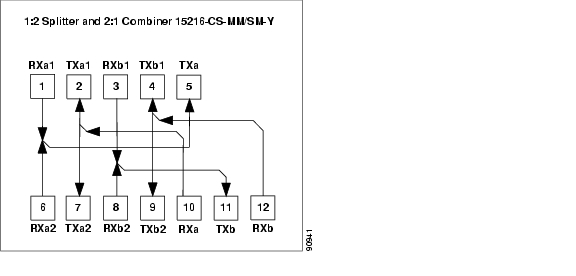
Figure 4-26 shows the unit block diagram of the Y-cable protection module. When the module is used in the coupler direction, the individual signals enter the module from the CPL-RXn ports and pass through a passive star coupler to the CPL-TX port.
It is important to note that the coupler is not meant to combine both the working and protect client card signals. The module allows a path for the working client transmit interface to connect to the network in the event the opposite interface in the protection pair should fail (the protecting interface switches to the working interface).
When the module is used in the splitter direction, the signal enters the module from the SPL-RX port and is split through a passive star coupler to the SPL-TXn ports. This module (although designed to pass wavelengths associated with the ONS 15216 32-channel plan) is not selective to specific wavelengths (units do not filter wavelengths).
Figure 4-26 1:2 Splitter and 2:1 Coupler (Y cable protection) Module Block Diagram
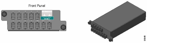
Figure 4-27 and Figure 4-28 show the ONS 15216 Y-Cable Protection FlexLayer Module. This module has two versions, one for single-mode applications and the other for multimode applications.
Figure 4-27 ONS15216 Y-Cable Protection FlexLayer Module (Single-Mode)
Figure 4-28 ONS15216 Y-Cable Protection FlexLayer Module (Multimode)
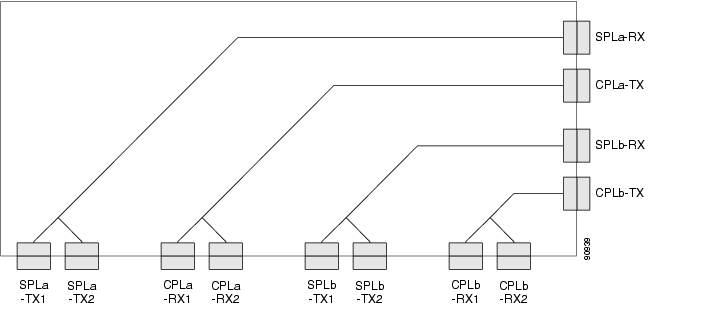
Figure 4-29 shows how the module front panel ports are mapped and labeled. The multimode unit is mapped and labeled the same as the single-mode unit.
Figure 4-29 Y-Cable Protection Component Connector Mapping and Labeling
See "Specifications"for unit specifications.
4.7 Four-Channel Variable Optical Attenuator (VOA) FlexLayer Module
The Four-Channel VOA module is a completely passive unidirectional component that allows equalizing the optical power of up to four channel groups. These modules are aimed to provide the ONS 15216 platform the capability of supporting VoD applications.
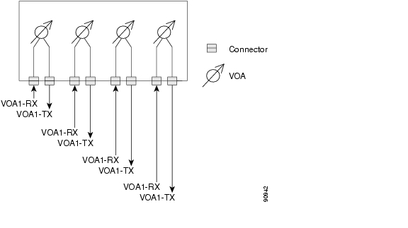
Figure 4-30 shows the unit functional block diagram. The input signals always flow from the VOA#-RX ports to the VOA#-TX ports. The pound (#) in the naming convention identifies the number ports and is limited from 1 to 4. The input signals are attenuated by the manual adjustment of the variable optical attenuators (VOAs) that are placed between the input and output ports.
Figure 4-30 Four-Channel VOA FlexLayer Module Block Diagram
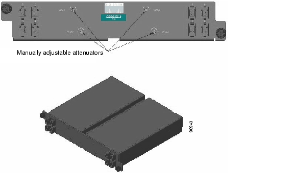
Figure 4-31 shows the ONS 15216 Four-Channel Variable Optical Attenuator FlexLayer Module.
Figure 4-31 ONS 15216 Four-Channel Variable Optical Attenuator FlexLayer Module
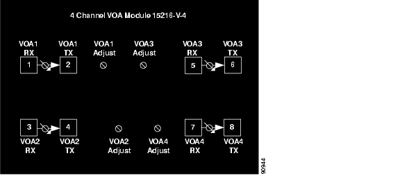
Figure 4-32 shows how the module front panel ports are mapped and labeled. The VOA#-TX ports are mapped with the even ports from 2 to 8 and the VOA#-RX ports are mapped with the odd ports from 1 to 7. VOA adjustment access is identified by VOA adjustment ports VOA 1 to 4.
Figure 4-32 4 Channel VOA Component Connectors' Mapping and Labeling
See "Specifications" for unit specifications.
![]()
![]()
![]()
![]()
![]()
![]()
![]()
![]()
Posted: Sun Apr 2 11:11:18 PDT 2006
All contents are Copyright © 1992--2006 Cisco Systems, Inc. All rights reserved.
Important Notices and Privacy Statement.