|
|

Table Of Contents
1.1 ONS 15216 EDFA3 Applications
1.2 Optical Safety Information
1.4.2 Constant Gain and Constant Pump Power Modes
1.4.9 Ethernet Hub Functionality
Introduction
This introductory chapter is designed to provide you with information about the ONS 15216 EDFA3 optical repeater. You should read this information before proceeding in order to familiarize yourself with the basic introductory information about the unit.
This chapter contains the following sections:
•
ONS 15216 EDFA3 Applications
1.1 ONS 15216 EDFA3 Applications
An erbium-doped fiber amplifier, or EDFA, is an optical repeater that amplifies an optical laser beam directly, bypassing opto-electronic and electro-optical (O/E and E/O) conversion. The EDFA uses a short length of optical fiber that has been treated or "doped" with the element erbium. When the laser that carries the signal causes the signal to pass through this fiber, energy is applied to boost, or amplify, the level of the signal.
In fiber optic systems, no fiber material is absolutely transparent. This causes the infrared light carried by a fiber to be attenuated as it travels through the material. Because of this attenuation, repeaters must be used in spans of optical fiber longer than approximately 100 kilometers.
The operating wavelength range of an EDFA extends over the entire C band (1530 to 1560 nm) and therefore provides a cost-effective solution for wavelength division multiplexing (WDM) applications. Where the use of O/E-E/O regenerators would require the demultiplexing and multiplexing of each single WDM channel at each regenerator site and an O/E-E/O pair for each channel, the ONS 15216 EDFA3 can regenerate all of the WDM signals together.
1.2 Optical Safety Information
The ONS 15216 EDFA3 is an optical device and requires attention to safety measures. See Appendix A, "Regulatory Compliance and Safety Information" for complete safety information.
Warning
Warning
Warning
Warning
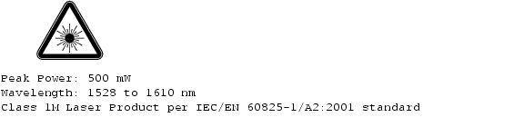
TL1 commands can be used to increase the level of laser energy. Necessary precautions must be taken to avoid exposure to laser energy when using these commands. Figure 1-1 and Figure 1-2 show laser safety warnings.
Figure 1-1 Laser Radiation Warning
Figure 1-2 Laser Specifications Warning
1.3 Block Diagrams
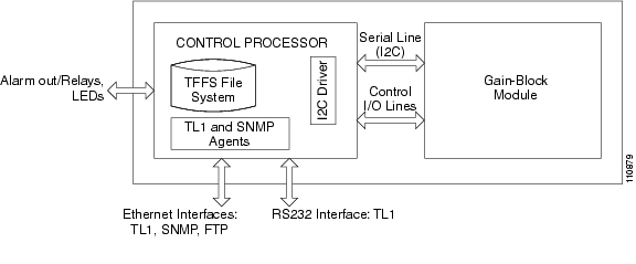
Figure 1-3 shows the block diagram of the ONS 15216 EDFA3. A Control Processor communicates with the gain block optical module via I2C protocol and runs the TL1 and SNMP agents for outside communication. The TL1 and SNMP interfaces are available on the two Ethernet ports. The TL1 interface is available also on the serial EIA/TIA-232 (RS-232) interface. The Control Processor also manages the alarm LEDs.
Figure 1-3 ONS 15216 EDFA3 Block Diagram
Figure 1-4 shows the block diagram of an optical module.
Figure 1-4 ONS 15216 EDFA3 Optical Gain Block Diagram
The Optical Gain Block is a two-stage amplifier. The signal enters through the port COM-RX and is amplified by the first stage. Then its accumulated chromatic dispersion is compensated by a Dispersion Compensation Unit (DCU) that is placed between the ports DC-TX and DC-RX. The signal is then amplified by the second stage of the amplifier and the signal exits from the port COM-TX. A MON port is provided to monitor the output signal. See Figure 2-3 on page 2-10 for a drawing of the actual unit.
1.4 ONS 15216 EDFA3 Features
The ONS 15216 EDFA3 optical amplifier enables the migration to next-generation all-optical networks, featuring:
•
•
You need to have a Simple Network Management Protocol (SNMP) manager to issue SNMP commands. Third-party SNMP managers include Cisco Transport Manager (CTM), HP OpenView Network Node Manager (NNM), and Open Systems Interconnection (OSI) NetExpert. Descriptions of SNMP commands in this document assume that you will be using Cisco Transport Manager (CTM).
The following list shows key features of the ONS 15216 EDFA3:
•
•
•
•
•
•
•
•
•
•
•
•
The following sections describe some of the features in the ONS 15216 EDFA3.
1.4.1 Transient Suppression
When the EDFA3 is working in Constant Gain mode and the number of channels at the input of the amplifier suddenly changes, a finite time occurs before the amplifier readjusts the pump power to keep the gain constant. Also, when the EDFA3 is working in Constant Power mode, a finite time occurs before the population inversion of the amplifier adjusts to the new value. This dynamic behavior is undesirable as it might cause bit errors. The ONS 15216 EDFA3 uses transient suppression to reduce the gain transient and the amount of time that the amplifier requires to recover from a change. This contributes to the suitability of the amplifier for add/drop applications.
1.4.2 Constant Gain and Constant Pump Power Modes
The ONS 15216 EDFA3 can work in Constant Output Power mode or in Constant Gain mode. When the amplifier is driven in Constant Output Power mode, the amplifier keeps the output power constant regardless of the input power. In this mode, the amplifier works essentially as a saturated amplifier and the per channel output power changes as the input channel number varies.
In contrast, Constant Gain mode ensures that the channel power at the amplifier output remains constant when a sudden change in the number of input channels occurs. In this way, the optical link is resilient to changes in the link traffic. Channels can be added or removed from the optical link without having to perform any operation on the amplifier. Also, when the amplifier works in Constant Gain mode, the link is resilient to failures of some of the channels of the link; the surviving channels will still be transported along the link with the same channel power.
The true variable gain simultaneously maintains high power output, low noise, and flat gain over the entire gain range by varying the laser's pump power in addition to adjusting a mid-stage VOA.
Constant gain is achieved using an automatic control circuit that adjusts pump power when changes in input power are detected. The ONS 15216 EDFA3 operates in Constant Gain mode by default. The two operating modes of the ONS 15216 EDFA3 are the following:
•
•
The ONS 15216 EDFA3 has two different gain ranges:
•
•
1.4.3 Dispersion Compensation
The mid-stage access ports (DC-TX and DC-RX) on the ONS 15216 EDFA3 are used to connect a Dispersion Compensation (DC) device between amplifier stages within the EDFA3. By placing the dispersion compensation between amplifier stages, the EDFA3 is compatible with 10-Gbps networks without compromising the optical link loss budget. This provides network designers with two benefits:
•
•
The insertion loss for the DC device must be between three and nine decibels (dB).
If a DC device is not going to be used, the mid-stage access ports need to be patched together with a 4-dB attenuator inline. This is because the firmware-controlled VOA that must used for gain flattening purposes has been designed around a minimum insertion loss of 3 dB. Without the DC-TX port being patched to the DC-RX either through a dispersion compensation device or a 4-dB attenuator, the EDFA3 does not operate properly.
1.4.4 Gain Flattening
The ONS 15216 EDFA3 automatically adjusts an internal VOA for gain flattening, to ensure constant gain over the entire wavelength range.
1.4.5 Low Noise
In analog and digital communications, signal-to-noise ratio is a measure of the relative strength of an optical signal compared to the electrical background noise, usually measured in decibels (dB).
An optical amplifier always adds optical noise to the amplified signal. The predominant source of noise in an EDFA is amplified spontaneous emissions (ASE). Usually the amount of noise inserted by an amplifier is measured by a figure of merit called Noise Figure (NF). In an optical amplifier, the NF depends on the gain (this usually gets higher when the gain decreases). The ONS 15216 EDFA3 has a worst case NF of 6.5 dB for a gain higher than 21 dB.
1.4.6 TL1 Interface
The ONS 15216 EDFA3 has a TL1 interface available to network operators and craftspersons. This TL1 interface is a line-oriented interface, allowing craft personnel and network operators to maintain a network element (NE) and the cards within an NE. The ONS 15216 EDFA3 uses a TL1 interface, which is described in Chapter 7, "TL1 Turn Up," Chapter 6, "About TL1 Commands," and Chapter 8, "TL1 Commands and Autonomous Messages."
1.4.7 SNMP MIBs
The ONS 15216 EDFA3 uses MIBs to contain definitions of management information that allow network systems to be remotely monitored, configured, and controlled.
A MIB is a formal description of a set of network objects that can be managed using SNMP. All other MIBs are extensions of the basic MIB. MIBs or MIB extensions exist for each set of manageable network entities.
1.4.8 Alarm LEDs
The ONS 15216 EDFA3 has seven LEDs:
•
•
•
•
Three of these LEDs, POWER, FAIL, and Loss of Signal (LOS), are located at the left side of the front panel of the ONS 15216 EDFA3. The two Ethernet LEDs are located at the top left and right sides of each Ethernet socket. When the module is powered on, an LED test is performed.
Detailed information about these LEDs is contained in the "5.2 Alarm LEDs" section on page 5-2.
1.4.9 Ethernet Hub Functionality
The ONS 15216 EDFA3 is equipped with an Ethernet hub. A port of the hub is connected with the Control Processor, while two other ports are available to the user with RJ-45 connectors, one on the front and one on the rear. In this way, the user can connect to the unit on one Ethernet port and use the second one to cascade the communication to other units in a daisy-chain configuration.
The ONS 15216 EDFA3 hub detects and corrects port polarity reversals. The hub also reconditions all data flowing through it:
•
•
•
•
The hub monitors and detects collisions, and forces jamming bit streams to inform all ports about the collisions.
![]()
![]()
![]()
![]()
![]()
![]()
![]()
![]()
Posted: Sat Sep 16 00:25:35 PDT 2006
All contents are Copyright © 1992--2006 Cisco Systems, Inc. All rights reserved.
Important Notices and Privacy Statement.