|
|

Table Of Contents
2.1.1 Optical Safety Functions
2.2.1 Constant Output Power Mode
2.5 Maximum Input Power Specification
2.9 Measurement Units and Representation
Specifications
The following material describes the specifications for the ONS 15216 EDFA3. The sections in this chapter describe the following:
•
Maximum Input Power Specification
•
2.1 Optical Specification
The specified values are valid over the full temperature range and full lifetime of the ONS 15216 EDFA3. ONS 15216 EDFA3 optical specifications are listed and described in Table 2-1 through Table 2-5.
Table 2-1 Wavelength Specification
DWDM1 channel wavelength plan, 100 GHz
4 skip 1
ITU-T wavelength grid channels 20 to 59
—
DWDM channel wavelength plan, 50 GHz
8 skip 2
ITU-T wavelength grid channels 19.5 to 59
—
Channel spacing
—
100 and 50
GHz
Total operating wavelength range
—
1530.0 to 1561.3
nm
1 DWDM = dense wavelength division multiplexing
Table 2-2 Optical Parameters
Gain ripple (peak to valley)
Tilt setpoint = 0 dB
—
—
1.5
dBm
Gain set resolution
Constant Gain mode
—
—
0.1
dB
Output power set resolution
Constant Power mode
—
—
0.1
dB
Mid-stage loss range
—
3
—
9
dB
Maximum total mid-stage output power
—
—
—
15
dBm
Maximum per-channel mid-stage output power
At 32 channels
—
—
0
dBm
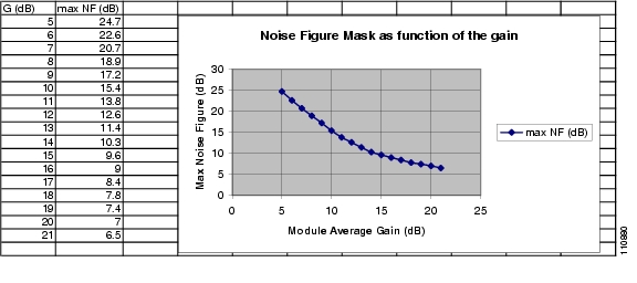
Noise Figure at G >= 21 dB
VOA1 at minimum loss
—
—
6.5
dB
Noise Figure at G = 5 dB
Tilt setpoint = 0 dB
—
—
24.7
dB
Noise Figure at 5 < G < 21 dB
See Figure 2-1
—
—
—
—
Polarization dependent gain
—
—
—
0.5
dB
Polarization mode dispersion
—
—
—
0.7
ps
Optical return loss
All optical ports
40
—
—
dB
1 VOA = variable optical attenuator
Figure 2-1 Noise Figure Mask as a Function of the Gain
2.1.1 Optical Safety Functions
The optical safety functions implemented on the ONS 15216 EDFA3 are:
•
2.1.1.1 Optical Safety Remote Interlock
The optical safety remote interlock (OSRI) function allows you to manually shut down the EDFA3 pump lasers using a TL1 command (ED-DWDM) or SNMP object (cerent15216EdfaGenericEdfa3Osri). This function is designed for safety purposes to avoid the risk for the operator to manage hazardous optical power level. The total time for laser shutdown after receiving a disable command is 100 ms.
Note
2.1.1.2 Automatic Laser Shutdown
The ONS 15216 EDFA3 performs an automatic laser shutdown (ALS) when a loss of input power (that is, power falls below the FailLow threshold) is detected at the input port of both stages:
•
•
The ALS shuts down the optical power at the following two optical output ports:
•
•
2.1.1.3 Automatic Power Reduction
The automatic power reduction function is used by the amplifier during the recovery after an ALS event. When the loss of signal (LOS) event is no longer present at the amplifier input, before going to the original power setpoint, the amplifier undergoes a transition to a safe reduced output power level of 8 dBm for 9 seconds.
2.1.2 Transient Suppression
Table 2-6 shows transient suppression specifications.
The previously indicated transient suppression specifications are referred to the following conditions:
•
•
•
•
•
2.2 Operation Modes
The ONS 15216 EDFA3 can be driven in one the following working modes:
2.2.1 Constant Output Power Mode
When the ONS 15216 EDFA3 is driven in Constant Output Power mode, the signal output power is set to the provisioned value. The user provisions the total power of the amplifier, while the firmware of the internal optical module automatically sets the output power of the two amplifier stages.
In this mode, the EDFA3 essentially works as a saturated amplifier. The output power remains constant when the input power changes. When channels are added or dropped at the amplifier input, the output channel power varies accordingly. In this mode, the amplifier is not resilient to the channel number variation at the amplifier input, so it should be used only in the installation phase.
The Constant Output Power control limits its action by constantly checking that the laser current never exceeds its maximum ratings. The control module calculates and provisions output power alarm thresholds every time the output power set point changes.
The firmware of the internal optical module compensates for the amplified spontaneous emission (ASE) noise generated by the amplifier. In other words, the amplifier computes the noise generated by the amplifier itself and sets the Signal Power to the provisioned value compensating for the Noise Power.
2.2.2 Constant Gain Mode
When the ONS 15216 EDFA3 is driven in Constant Gain mode, the amplifier gain is set to the provisioned value. The user provisions the total gain of the amplifier, while the firmware of the internal optical module automatically sets the gains of the two amplifier stages.
In this mode, the channel output power remains constant when the number of input channels changes. Therefore, in this mode, the amplifier is resilient to a failure of a transmitter or of an optical add/drop multiplexer (OADM) card. Also when the amplifier is in Constant Gain mode, the link can be upgraded adding or removing channels without performing any management operation on the amplifier. Therefore, this should be the preferred mode when the link is in normal operating conditions.
The firmware of the internal optical module compensates for the ASE noise generated by the amplifier. The amplifier computes the noise generated by the amplifier itself and sets the Signal Gain to the provisioned value compensating for the Noise Power.
2.3 Gain Tilt Control
As a default, the amplifier gain tilt is set to zero. The firmware automatically controls the internal VOA to achieve a flat gain.
The user can provision a gain tilt different from zero to compensate for gain tilt produced by other optical components preceding the amplifier. The gain tilt control is active only in the standard gain range (5 to 21 dB). The tilt can be set between -3 and + 3 dB.
2.4 Alarm Thresholds
The ONS 15216 EDFA3 uses thresholds. It raises or clears alarms when these thresholds are crossed. The EDFA3 has both absolute and relative thresholds. Absolute thresholds are independent of any other parameter setpoint and can be user-provisioned, whereas the relative thresholds are automatically calculated depending on the actual setpoint of a parameter, and their values cannot be provisioned by the user.
Table 2-7 lists all the provisionable thresholds, their description, their default value and their provisioning range.
Table 2-7 Threshold Behavior
GAINTHDL
Gain Degrade Low Threshold
Gain Setpoint - 2dB
—
GAINTHDH
Gain Degrade High Threshold
Gain Setpoint + 2dB
—
LINE1TXPWRTHDL
Power Degrade Low Threshold LINE1TX Port
LINE1TXPWRSP - 2dB
—
LINE1TXPWRTHDH
Power Degrade High Threshold LINE1TX Port
LINE1TXPWRSP + 2dB
—
LINE1TXPWRTHFL
Power Fail Low Threshold LINE1TX Port
-6 dBm
-10, +14 dBm
See Note BelowLINE1RXPWRTHFL
Power Fail Low Threshold LINE1RX Port
+10 dBm
-49, +13 dBm
LINE2RXPWRTHFL
Power Fail Low Threshold LINE2RX Port
-33 dBm
-49, +15 dBm
PWRBUSMIN
Power Bus A and B Minimum Voltage
40 V
0, 47 V
PWRBUSMAX
Power Bus A and B Maximum Voltage
57 V
49, 57 V
MAXCTMP
Maximum Case Temperature
65 degrees C
60, 100 degrees C
(140, 212 degrees F)MINCTMP
Minimum Case Temperature
-5 degrees C
-10, 30 degrees C
(14, 86 degrees F)
Note
(-10dBm) <= LINE1TXPWRTHFL<= (LINE1TXPWRSP - 3dBm)
This relationship implies that the LINE1TXPWRTHFL threshold must always be set at least 3dBm below the LINE1TXPWRSP set point (but not below -10dBm), as a result, the maximum +14dBm LINE1TXPWRTHFL threshold can only be set when the LINE1TXPWRSP set point is also set to it's maximum value of +17dBm.
(Refer to section 10.7.2 Table 10-24 for LINE1TXPWRSP range)2.5 Maximum Input Power Specification
The ONS 15216 EDFA3 operates at a gain setting between 5 and 21 dB, standard gain range, and between 21 and 38.5 dB, extended gain range. As the total output power of the amplifier cannot exceed 17 dBm, each gain setting has a maximum input power. The maximum input power is given by the maximum output power, 17 dBm, minus the gain setting. For example, at a gain setting of 22 dB, the maximum input power is -5 dBm. Prolonged operation beyond the maximum input power can shorten the life of the ONS 15216 EDFA3.
Optical attenuators are required to bring total input power to less than the maximum input power when operating in constant gain mode.
2.6 Electrical Specifications
The ONS 15216 EDFA3 uses a power supply that meets the electrical specifications listed in Table 2-8.
A separate AC/DC converter for use with the ONS 15216 EDFA3 can be ordered from Cisco.
2.6.1 Electrical Interface
Table 2-9 describes the external electrical interfaces for the ONS 15216 EDFA3. See Figure 2-3 for a graphic showing the electrical connectors.
.
2.7 Mechanical Specifications
Table 2-10 lists the ONS 15216 EDFA3 mechanical specifications.
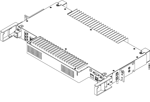
2.8 External Features
The ONS 15216 EDFA3 has the following external features:
•
•
•
•
•
•
•
•
•
•
Figure 2-2 displays a mechanical outline of the external features of the ONS 15216 EDFA3.
Figure 2-2 External Features
2.8.1 Footprint
The ONS 15216 EDFA3 is housed in a 1-RU, 19-inch/23-inch (482-mm/584-mm), rack-mounted shelf. However, a 3-RU spacing is required for ventilation. All-front access is available for fibers, power, alarm contacts, and management interfaces. Rear access is available for power, alarm, and management interfaces.
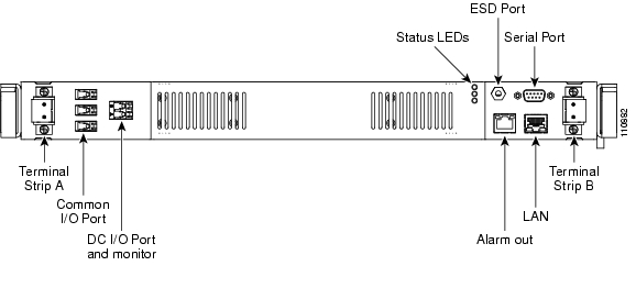
2.8.1.1 Front Panel
Figure 2-3 shows the ONS 15216 EDFA3 front panel in detail. The front panel provides an all-front access (fibers, power, alarm contact, and management interface) that complies with international standards.
Figure 2-3 ONS 15216 EDFA3 Front Panel
Table 2-11 describes the ONS 15216 EDFA3 front panel features.
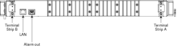
2.8.1.2 Rear Panel
Figure 2-4 shows the ONS 15216 EDFA3 rear panel. Table 2-12 lists the rear panel features.
Figure 2-4 ONS 15216 EDFA3 Rear Panel
2.9 Measurement Units and Representation
Table 2-13 lists the measurement units used for the ONS 15216 EDFA3 parameters exported to the TL1 and SNMP interfaces:
Table 2-13 Measurement Units for ONS 15216 EDFA3 Parameters
dBm
Power
dB
Gain and insertion loss
V
Power bus voltage
The TL1 interface represents the exported values as floating point. The SNMP interface represents the exported values as integers, removing the decimal point.
![]()
![]()
![]()
![]()
![]()
![]()
![]()
![]()
Posted: Sat Sep 16 00:44:17 PDT 2006
All contents are Copyright © 1992--2006 Cisco Systems, Inc. All rights reserved.
Important Notices and Privacy Statement.