cc/td/doc/product/ong/15216/216edf
hometocprevnextglossaryfeedbacksearchhelp
PDF

Table Of Contents

Communicating with the ONS 15216 EDFA3

5.1  Alarm Out Relay Interface (RJ-45)

5.2  Alarm LEDs

5.2.1  POWER LED (Green)

5.2.2  FAIL LED (Red)

5.2.3  LOS LED (Yellow)

5.2.4  Ethernet Socket LEDs

5.3  Communicating with the EDFA3 Through a Serial EIA/TIA-232 (RS-232) Interface


Communicating with the ONS 15216 EDFA3


This chapter contains information about communicating with the ONS 15216 EDFA3. The sections in this chapter contain the following information:

Alarm Out Relay Interface (RJ-45)

Alarm LEDs

Communicating with the EDFA3 Through a Serial EIA/TIA-232 (RS-232) Interface

5.1  Alarm Out Relay Interface (RJ-45)

The ONS 15216 EDFA3 Alarm Out (RJ-45) port reports alarm status for the following:

Loss or degradation of electrical power

Laser pump overheating or excessive pump current, output power, gain, or case temperature

Loss or degradation of optical input signal

These alarms can be connected to a network operations center (NOC) using the following methods:

Cisco ONS 15454 miscellaneous discrete input (See Chapter 13, "Network Access to the ONS 15216 EDFA3 Using the ONS 15454" for more details about the ONS 15454.)

Central office (CO) alarm panel/system

Table 5-1 provides the ONS 15216 EDFA3 RJ-45 alarm pinout and alarm definitions.

Table 5-1 Alarm Pinout and Definitions (RJ-45) 

Relay
Pinout
Description

0

1 (0+)

HW failure.

2 (0-)

1

3 (1+)

Laser pump temperature or bias is out of range.

4 (1-)

2

5 (2+)

Loss of optical input signal or input signal is below threshold.

6 (2-)

3

7 (3+)

Loss of electrical power or out of range for Bus A or Bus B while in duplex mode.

8 (3-)


The following procedure describes how to set up alarm contacts. In order to accomplish this, you must:

Connect the RJ-45 cable to the panel of the ONS 15454 shelf

Connect the alarm cable to the alarm system contacts

To set up alarm contacts, follow these steps:


Step 1 Connect the RJ-45 cable to the stub-end connector using a #22 AWG solid wire.


Note Note that the cable and connector are not provided.


Step 2 Connect the alarm cable to the alarm system contacts:

a. Cisco ONS 15454 medium-dependent interface (MDI) wire wrap pins, located on the rear panel of the ONS 15454 shelf

b. CO alarm panel

Refer to Table 5-1 for information concerning alarm contacts. Refer to the "Alarm LEDs" section for information about the ONS 15216 EDFA3 alarm LEDs.


5.2  Alarm LEDs

The ONS 15216 EDFA3 has seven LEDs:

POWER

FAIL

LOS

Ethernet socket (two sockets with two LEDs on each socket)

Three of these LEDs, POWER, FAIL, and loss of signal (LOS), are located at the left side of the front panel of the ONS 15216 EDFA3. The two Ethernet LEDs are located at the top left and right sides of the Ethernet socket. When the module is powered on, an LED test is performed.

The following table summarizes the external alarms LEDs and contacts.

Table 5-2 LED Indicators of Normal and Fault States 

LED
LED Normal State
LED Fault State
Fault Description
ALARM OUT Pair
ALARM OUT Contact Normal State
ALARM OUT State
Serial Alarms

Power

ON

OFF

Both A and B DC Power have failed.

1

Open

Closed

None

Flash

A or B power has failed.

4

Open

Closed

Either "A Power Fail" or "B Power Fail"

Fail

OFF

ON

High pump laser current

2

Open

Closed

Fail

LOS

OFF

ON

Input optical signal is below provisioned threshold.

3

Open

Closed

LOS


5.2.1  POWER LED (Green)

The POWER LED is green. This LED functions as follows:

ON: -48 VDC power is within tolerance. (Power Bus A and Power Bus B are powered normally.)

OFF: No -48 VDC power, or power is out of tolerance from the internal power supply. (Power Bus A and Power Bus B are not powered.)

Flashing: In duplex mode, Power Bus A or Power Bus B has failed or is out of tolerance. In simplex mode, Power Bus A is out of tolerance.

In the OFF condition, the first pair of alarm relay contacts in the RJ-45 connector changes from a normally open condition to a closed condition. The LED and alarm automatically reset when the condition clears. (For additional alarm contact closure information, see the "Alarm Out Relay Interface (RJ-45)" section on page 5-1.)

5.2.2  FAIL LED (Red)

The FAIL LED is red. This LED has two states:

ON: The laser pump bias, laser pump temperature, output power, gain, or case temperature is out of tolerance. (A major internal failure has occurred.)

OFF: The laser pump bias or laser pump temperature is in the specified range (or no -48 VDC power is present).

In the ON condition, the second pair of alarm relay contacts in the RJ-45 connector changes from a normally open to a closed condition. If an invalid input optical signal is applied to the ONS 15216 EDFA3, the FAIL LED is illuminated. The LED and alarm automatically reset when the condition clears.

5.2.3  LOS LED (Yellow)

The loss of signal (LOS) LED is yellow. This LED has two states:

ON: The optical input power to the ONS 15216 EDFA3 is below the loss of input threshold. (A LOS threshold decision occurs.)

OFF: The optical input power is within the input threshold (or no -48 VDC power is present).

In the ON condition, the third pair of alarm relay contacts in the RJ-45 connector changes from a normally open condition to a closed condition. The LED and alarm automatically reset when the condition clears.

5.2.4  Ethernet Socket LEDs

Two Ethernet socket LEDs are located at the top left and right sides of the Ethernet socket. These LEDs are both green. These LEDs function as follows:

If the left Ethernet socket LED is on, the link is up.

If the right Ethernet socket LED is on or flashing, there is Ethernet traffic.

5.3  Communicating with the EDFA3 Through a Serial EIA/TIA-232 (RS-232) Interface

This section describes communication with the ONS 15216 EDFA3 using a serial connection. Establishing a serial communications link with a ONS 15216 EDFA3 requires the equipment listed in Table 5-3.

Table 5-3 Equipment Checklist

Hardware
Comments

Laptop or VT100, running HyperTerminal.

User-provided. HyperTerminal can be found in the Microsoft Windows Accessories menu.

EIA/TIA-232 (RS-232) cable with DB-9F/DB-9M connectors wired.

Provides EIA/TIA-232 (RS-232) link to ONS 15216 EDFA3.


To set up an EIA/TIA-232 (RS-232) link to the ONS 15216 EDFA3, use the following procedure. (The procedure uses HyperTerminal and a connection through the COM1 port on the PC.)

This procedure consists of:

Physically connecting the ONS 15216 EDFA3 to a laptop

Opening HyperTerminal

Using HyperTerminal to set up communications between the PC and the ONS 15216 EDFA3

Configure the port settings

Configure the ASCII settings


Step 1 Connect the DB-9F end of the EIA/TIA-232 (RS-232) data cable (straight cable, user provided) to the laptop COM1 port.

Step 2 Connect the DB-9M end of the EIA/TIA-232 (RS-232) data cable to the EIA/TIA-232 (RS-232) serial port connection on the front panel of the ONS 15216 EDFA3 ( Figure 5-1).

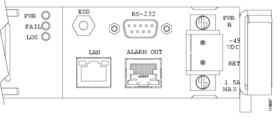
Figure 5-1 EIA/TIA-232 (RS-232) Serial Port Connector on the ONS 15216 EDFA3

Step 3 To configure a connection, open HyperTerminal. (HyperTerminal can be found in the Microsoft Windows Accessories > Communications menu.)

Step 4 A Connection Description dialog box appears ( Figure 5-2). Type "Optical Amplifier" in the Name field and select an icon to use for the connection, for example the telephone icon at the bottom left of the dialog box.

Figure 5-2 Hyper Terminal Connection Description Dialog Box

Step 5 Click OK.

Step 6 In the Connect To dialog box (Figure 5-3), click COM1 in the Connect using field.

Step 7 Click OK.

Figure 5-3 HyperTerminal Connect To Dialog Box

Step 8 Configure the Port Settings in the COM1 Properties dialog box as shown in Figure 5-4.

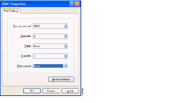
Figure 5-4 HyperTerminal COM1 Properties Dialog Box

Step 9 Click OK when done.

Step 10 In the HyperTerminal main window, select File > Properties.

Step 11 Make sure that the Connect To tab in the Optical Amplifier Properties dialog box is selected.

Step 12 Ensure that Direct to Com1 is selected in the Connect using field.

Step 13 Click the Settings tab. The dialog box shown in Figure 5-5 appears.

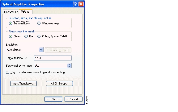
Figure 5-5 Optical Amplifier Properties Dialog Box (Settings Tab)

Step 14 Click the ASCII Setup button.

Step 15 Configure the selections in the ASCII Setup dialog box as shown in Figure 5-6.

Figure 5-6 HyperTerminal ASCII Setup Dialog Box

Step 16 Click OK when done.

Step 17 Click OK in the Optical Amplifier Properties dialog box to return to the main HyperTerminal window.

The ONS 15216 EDFA3 default TL1 login screen appears.


Table 5-4 shows the Windows HyperTerminal configuration.

Table 5-4 Windows HyperTerminal Configuration Summary

Parameter
Value

Emulation

ANSI, 9600 bps

Data Bits

8

Parity

None

Stop Bit

1

Flow Control

None


hometocprevnextglossaryfeedbacksearchhelp

Posted: Sat Sep 16 09:28:41 PDT 2006
All contents are Copyright © 1992--2006 Cisco Systems, Inc. All rights reserved.
Important Notices and Privacy Statement.