|
|

Table Of Contents
Local Serial Communication Setup
Remote Communication Component Requirements
Setting and Saving Modem Settings
Connecting to the ONS 15216 EDFA1
Provisioning and Monitoring
Each ONS 15216 EDFA1 is equipped with a microcontroller that allows you to provision and monitor several operating parameters. The microcontroller generates an alarm in event of failure. For example, if the performance of one of several operating parameters is out of range, an alarm is generated. Alarms are recorded and stored in the microcontroller's memory and can be retrieved for review.
You provision and monitor the ONS 15216 EDFA1 using an RS-232 serial port located in the front panel. You can connect locally or remotely using a modem. A DB-9 female pinout is required to connect to the serial port.
This chapter describes how to set up communications with an ONS 15216 EDFA1 using the following methods:
•
Local serial interface
•
•
Local Serial Communication Setup
To establish a serial communications link with an ONS 15216 EDFA1 you need the equipment listed in Table 4-1. To set up an RS-232 serial connection, follow the steps in Table 4-2.
Table 4-2 RS-232 Configuration
1
Connect the DB9(R) end of the RS-232 data cable to the COM port on your laptop.
2
Connect the other end of the RS-232 data cable to the RS-232 serial port connection on the 15216 EDFA1 front access panel ( Figure 2-3).
3
Open HyperTerminal.
4
Type Optical Amplifier, select an icon, and click OK.
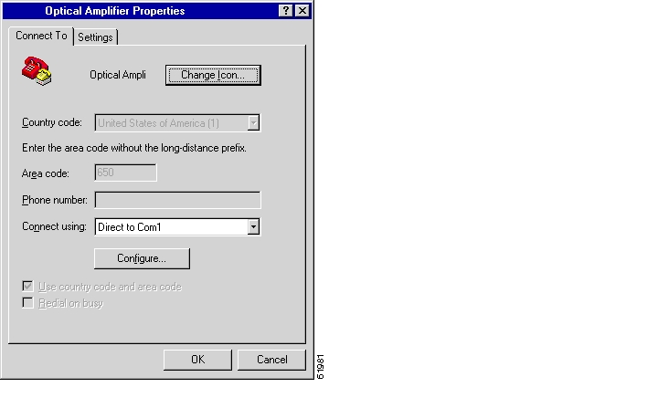
In the Connect To dialog box ( Figure 4-1), Direct to Com1 must be selected in the Connect using field. Click OK when done.
5
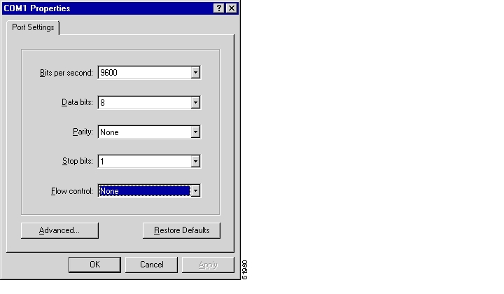
Configure the Port Settings in the COM1 Properties dialog box as shown in Figure 4-2.
6
From the HyperTerminal menu bar, select File>Properties to display the Properties dialog box. Click the Connect to tab ( Figure 4-3).
Make sure that Direct to Com1 is selected in the Connect using field.
7
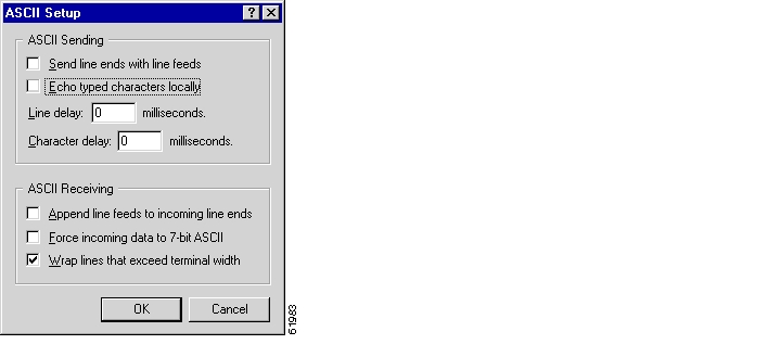
Click the Settings tab shown in Figure 4-4 and click the ASCII Setup button. Configure the ASCII Setup window as shown in Figure 4-5.
8
Click OK to return to the HyperTerminal main screen.
9
Set the address using the !xx syntax, where xx can be any value from 00 to 99. At the prompt, login using the @xx syntax, where xx can be any value from 00 to 99.
10
Click Enter once.
Figure 4-1 HyperTerminal Connect To Dialog Box
Figure 4-2 HyperTerminal COM1 Dialog Box
Figure 4-3 HyperTeminal Connect To Tab
Figure 4-4 Hyperterminal Settings Tab
Figure 4-5 HyperTerminal ASCII Setup Dialog Box
Note
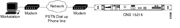
Figure 4-6 Remote Communication
Remote Communication Component Requirements
Table 4-3 lists the components required to communicate remotely with an ONS 15216 EDFA1. Table 4-3 is divided into two sections: first the Remote Site and then the Local Site. The Remote Site section lists components needed at the site that contains the ONS 15216 EDFA1 and the Local Site section lists components needed at the user site.
Modem Signals
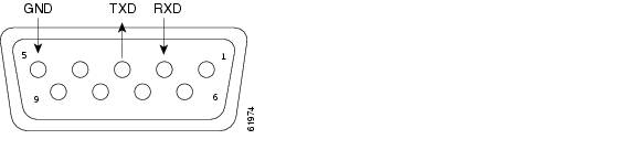
The only signals required for communication are TXD (transmit), RXD (receive), and SIGNAL GROUND. By adjusting the modem manufacturers' settings, the other signals can be ignored.
Modem Power Up
The modem has a dip switch that will override certain NVRAM settings during a power up. For consistent operation throughout the power cycles, you must set the dip switches as follows.
Configuration Settings
After configuring the dip switch settings, you must set up each modem configuration using a terminal program such as Microsoft Windows HyperTerminal.
Using the manufacturer's recommendations, connect the modem to the serial port on your PC using a DB9-25 modem cable.
Set the terminal communication parameters as follows:
•
•
•
•
Table 4-5 gives a brief description of the modem settings that can be stored in NVRAM. These settings will survive power supply interruptions. Use these settings to configure each modem.
Setting and Saving Modem Settings
To set and save modem settings, enter the following command to the terminal program and to each modem:
atb0e0f1m1q1v1x1y0at&a3&b1&c1&d0&g0&h0&i0&k0s0=1at&m5&n8&p1&r1&s1&t5&u8&y1s2=128at&w0Connecting to the ONS 15216 EDFA1
At this point, the modems, PC, and ONS 15216 EDFA1 should be physically setup as displayed in Figure 4-6.
The ONS 15216 EDFA1 and modem are connected through an RS-232 port using a DB-9 connector. Use Figure 4-7 to properly connect the ONS 15216 EDFA1 to the modem. Normally, a craftsperson connects only pins 2, 3, and 5.
Note
Figure 4-7 DB-9 pinouts
Using the terminal program from the PC, enter the ATDT command with the appropriate telephone number to call the remote ONS 15216 EDFA1 modem. After the modems synchronize, log into the ONS 15216 EDFA1 using the @ command. See Chapter 5, "Command Line Reference," for additional information about commands.
Alarm Contact Closures
The ONS 15216 EDFA1 provides a front panel single Form C discrete external alarm output. The external alarm output is through the eight wires of an RJ-45 connector.
The following events are reported by the discrete external alarms through individual alarm contacts:
•
•
•
Note
Table 4-6 lists the RJ-45 pinout for the alarms.
Table 4-6 RJ-45 Pinout
1
Alarm 0+ (Power)
2
Alarm 0-
3
Alarm 1 +(Major)
4
Alarm 1 -
5
Alarm 2 +(Minor)
6
Alarm 2 -
7
Alarm 3 + (No Connection)
8
Alarm 3
![]()
![]()
![]()
![]()
![]()
![]()
![]()
![]()
Posted: Sun Apr 2 03:19:02 PDT 2006
All contents are Copyright © 1992--2006 Cisco Systems, Inc. All rights reserved.
Important Notices and Privacy Statement.