|
|

Table Of Contents
Command Line Reference
This chapter describes the ONS 15216 EDFA1 software command set and includes information about each command's syntax, function, and password protection status.
Note
To obtain the syntax for any command, enter the command followed by a space and the question mark character (?). To obtain a complete list of all commands, type the HELP command.
ONS 15216 EDFA1 Operation
There are two types of ONS 15216 EDFA1 operations: special and normal.
Special ONS 15216 EDFA1 operations are described in Table 5-1.
Commands for operating the ONS 15216 EDFA1 under normal conditions are discussed in detail beginning in the "User Commands" section. Under normal operation, the unit behaves according to the specifications outlined in "Applications."
Note
User Commands
Each command in this chapter is described in the following format:
If you need additional information about a specific command or its syntax, enter the command followed by a question mark (?).
The following example displays the HELP command screen . See the "HELP" section for more specific information.
Example 5-1 HELP Command:
0-0>HELPSystem Status System Commands Setup Commands Maintenance------------------------------------------------------------------------ALARM ALMDSBL SET_LOSTH CUTOVERHELP ALMENBL SETGT LOADLD CONFIG SETI SETADDRPRM LOGOUT SETOUT SRESETSTAT PASS SETPVER------------------------------------------------------------------------Enter 'Command ?' for syntax0-0>Measurement Parameters
The format for measurement parameters is as follows:
% [width].[precision]type,
Additional parameters include:
•
•
•
Additional information regarding measurement parameters can be found in the "PRM" section.
Login Session
@XY
None given
N/A
N/A
Login to unit with address XY
Explanation:
To begin a command session, you need to log in to the ONS 15216 EDFA1 . Typing the '@' character while logged into a unit immediately terminates the command session. Table 5-2 displays the ONS 15216 EDFA1 address parameters.
Example 5-2 @XY Command:
@xy
x-y>
Table 5-2 EDFA Address Parameters
x
0-9
First half of EDFA address
y
0-9
Second half of EDFA address
Note
To begin a session, enter @xy followed by a carriage return (where xy is the address of the module). The address of the ONS 15216 EDFA1 is a two-digit number from 00 to 99. In this document, the default address 00 is used for the ONS 15216 EDFA1.
The ONS 15216 EDFA1 ends every command by returning the following prompt: a-b> (where ab is the address of the ONS 15216 EDFA1). The prompt does not appear with the following commands:
•
•
•
•
•
The LOGOUT command should always be used to terminate a session.
Password Protection
Password protection is applied to commands that can change the mode of the ONS 15216 EDFA1 operation. You are required to enter the password at login to gain access to these commands.
CISCO is the default password. See the "PASS" section for information about changing passwords
Error Handling
Unaccepted commands result in an error message. Table 5-3 lists and describes error messages.
Example 5-3 Error Message:
0-0>COMMANDError message0-0>
System Status Commands
This section describes system status commands.
N/A
N/A
Displays alarm status or clears alarm counts
ALARM
Explanation:
Table 5-4 lists the alarms tracked by the ONS 15216 EDFA1.
To display the current status of alarms, type the ALARM D command.
Example 5-4 ALARM D command:
0-0>ALARM DPump 1 Pump 2Name Type Crnt Cnt Crnt Cnt DescrLCRNT Minor xxxxx yyy xxxxx yyy Excessive pump crnt/pump biasLTMP Minor xxxxx yyy xxxxx yyy LD temp out-of-rangeEDFA 1Name Type Crnt Cnt DescrLPOUT Major xxxxx yyy Loss outp pwrLPIN Major xxxxx yyy Loss inp pwrGAIN Major xxxxx yyy Gain out-of-rangeCTMP Major xxxxx yyy Case temp out-of-range0-0>Table 5-5 provides information for interpreting the results of an ALARM D command.
Table 5-5 Alarms
XXXXX
Alarm
Alarm is set
Dsbl
Alarm is disabled
OK
Alarm is cleared
YYY
0..255
Count of alarm activations.
To clear all alarm counts, type the ALARM C command.
Example 5-5 Alarm C Command:
0-0>ALARM CAlarms cleared0-0>HELP
N/A
N/A
Lists available commands
Displays list of available user commands.
Example 5-6 HELP command results:
0-0>HELPSystem Status System Commands Setup Commands Maintenance------------------------------------------------------------------------ALARM ALMDSBL SET_LOSTH CUTOVERHELP ALMENBL SETGT LOADLD CONFIG SETI SETADDRPRM LOGOUT SETOUT SRESETSTAT PASS SETPVER------------------------------------------------------------------------Enter 'Command ?' for syntax0-0>LD
N/A
N/A
Display the control mode of each laser diode pump.
Displays the current laser status (see Example 5-7 ). Laser modes of operation are listed in Table 5-6.
Example 5-7 LD Command:
0-0>LDLD n: mmmmmmmmmmmmmmmmmmmmmmmmLD n: mmmmmmmmmmmmmmmmmmmmmmmm0-0>
PRM
N/A
N/A
Displays the latest measurements for the specified laser pump and EDFA
When the PRM 1|2 command is entered, the parameters for pump 1 and 2 are displayed. (see Example 5-8). This command displays the same line of parameters as the STAT command without the header and one line at a time.
Example 5-8 PRM Command:
0-0>PRM 11 aaa.a/bb.b ccccc ddd.dd eeee.ee ff.ff ggg.g hhhh.h/iiii.ii jjjj.jj/kkk.kk lll.l0-0>PRM 22 aaa.a/bb.b ccccc ddd.dd eeee.ee ff.ff ggg.g hhhh.h/iiii.ii jjjj.jj/kkk.kk lll.l0-0>
Note
Use the following formats to specify displayed parameters such as width, precision, and type:
•
•
•
•
Table 5-7 lists the measurement parameters used to interpret the results of a PRM 1|2 command.
STAT
STAT [interval], 1-255 sec
N/A
N/A
Print the control mode of each pump and then periodically print the pump and EDFA status.
Displays EDFA status ( Example 5-9).
The period between updates ranges from 1 to 255 seconds and is specified as an argument to the STAT command. The default update rate is one time per second. To end the status-update printing and return to the prompt, press <Ctrl-X>.
While in STAT mode, line feeds are suppressed, and only carriage returns can achieve the effect of a continuously updated status line under a stationary header. This mode is intended for a craftsperson, whereas the PRM command is intended for a computer controlling the EDFA.
Laser diode pump control modes are displayed in the same format as the LD command. The only exception is that the note <<< Ctrl-X to Stop >>> which is printed on the same line as the first laser diode pump's control mode.
Format fields are identical to the PRM command.
Example 5-9 STAT Command:
0-0>STAT 1LD 1: Const Pump Crnt 10(mA) <<< Ctrl-X to Stop >>>LD 2: Const Pump Crnt 10(mA)LD T/To TEC LDPwr LDCrnt Amb DC In Out Gain(C) (mA) (mW) (mA) (C) (V) (uW/dBm) (mW/dBm) (dBm)1 25.5/25.5 39 0.49 9.92 30.25 5.2 0.0/-120.00 0.00/-90.00 30.0VER
N/A
N/A
Displays general information about the EDFA
Displays module details.
Example 5-10 VER Command:
0-0>VERCISCO Optical Amplifier, ver.4.20, May 05, 00Ser.# Q17DA1100003 Rev. BActive Plane: 1Inactive ver. 4.16ALARM D to see alarms0-0>0-0>VERaaaaaaaaaaaaaaaaaaaaaaaa, ver.bbbb, ccccccccccSer.# dddddddddddd Rev. eeeeeeeeeActive Plane: fInactive ver. gggghhhhhhhhhhhhhhhhhhhhhh0-0>Fixed widths are variable unless specified. Delimiters include the comma, period, pound, colon, space, carriage return, and line feed. Use Table 5-8 to interpret the VER command details.
System Commands
The following section describes system commands.
ALMDSBL
Yes
Yes
Disables an alarm
Explanation:
When an alarm is linked exclusively to a pin, that alarm can be disabled and its output pin set to VLO (Voltage Low). The exceptions are the loss of output alarm and the gain alarms.
For example, to disable the laser-chip temperature alarm of the second pump, type ALMDSBL LTMP 2. The alarms display. If the alarm is active, pin 10 on the DB-25 connector changes states from VHI (Voltage High) to VLO.
0-0>ALMDSBL LTMP 20-0>ALARM DPump 1 Pump 2Name Type Crnt Cnt Crnt Cnt DescrLCRNT Minor OK 0 OK 0 Excessive pump crnt/pump biasLTMP Minor OK 0 Dsbl 0 LD temp out-of-rangeEDFA 1Name Type Crnt Cnt DescrLPOUT Major Dsbl 0 Loss outp pwrLPIN Major Dsbl 0 Loss inp pwrGAIN Major Dsbl 0 Gain out-of-rangeCTMP Major OK 1 Case temp out-of-range
Note
ALMENBL
Yes
Yes
Enables alarm checking for the specified alarm
Explanation:
The following example displays a disabled alarm (the second laser pump's chip temperature alarm), enabled by the ALMENBL LTMP 2 command:
Example 5-11 ALMENBL Command:
0-0>ALARM DPump 1 Pump 2Name Type Crnt Cnt Crnt Cnt DescrLCRNT Minor OK 0 OK 0 Excessive pump crnt/pump biasLTMP Minor OK 0 Dsbl 0 LD temp out-of-rangeEDFA 1Name Type Crnt Cnt DescrLPOUT Major Dsbl 0 Loss outp pwrLPIN Major Dsbl 0 Loss inp pwrGAIN Major Dsbl 0 Gain out-of-rangeCTMP Major OK 1 Case temp out-of-range0-0>ALMENBL LTMP 20-0>ALARM DPump 1 Pump 2Name Type Crnt Cnt Crnt Cnt DescrLCRNT Minor OK 0 OK 0 Excessive pump crnt/pump biasLTMP Minor OK 0 OK 0 LD temp out-of-rangeEDFA 1Name Type Crnt Cnt DescrLPOUT Major Dsbl 0 Loss outp pwrLPIN Major Dsbl 0 Loss inp pwrGAIN Major Dsbl 0 Gain out-of-rangeCTMP Major OK 1 Case temp out-of-range0-0>CONFIG
Yes
Yes
Saves the current EDFA configuration
Explanation:
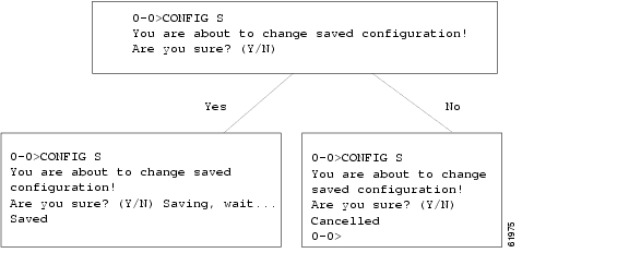
Configuration data consists of the control mode for each laser, all alarm enable/disable states, and loss of input threshold. After reset, the EDFA will use the saved configuration as the starting point for EDFA control.
As shown in Figure 5-1, entering the CONFIG S command followed by the letter Y saves the configuration. If you enter CONFIG S followed by the letter N, the save operation will be cancelled.
Figure 5-1 CONFIG S Command Path Diagram
Note
LOGOUT
N/A
N/A
Logout of current session
Explanation:
The LOGOUT command returns the current prompt and terminates the command line interface serial session. The ONS 15216 EDFA1 will not respond to any further commands unless you perform a login or address bootstrap.
Example 5-12 LOGOUT Command:
0-0>LOGOUT0-0>
Warning
Setup Commands
The following section describes setup commands.
SET_LOSTH
Yes
Yes
Set, get, or disable the loss-of-signal threshold
Explanation:
This command performs the following three functions:
•
•
•
Figure 5-1 The following example displays the SET_LOSTH command.
Example 5-13 SET LOSTH Command:
0-0>SET_LOSTH aaa.aaOK0-0>SET_LOSTHbbb.bbdBm0-0>SET_LOSTH DOK0-0>Use Table 5-9 to interpret the results of a SET_LOSTH command
.
Note
PASS
N/A
Yes
Gains access to password protected commands and can change password
Explanation:
Before using any password protected commands, you must first enter the correct password. For example, you must enter the correct password before switching the ONS 15216 EDFA1 operating mode to temperature-compensated constant gain mode (SETGT command, see Figure 5-1).
The system returns a "wrong password" for any incorrect passwords entered. When you enter the correct password, all password protected commands become accessible.
To change the password, use the PASS command followed by the old password and then the new password. In Example 5-14, after you enter the correct password (ENTER) the password is changed with the new PASS ENTER OPEN command.
Note
Example 5-14 PASS Command:
0-0>SETGTPassword required0-0>PASS ABCDWrong password0-0>PASS ENTERPass OK0-0>PASS ENTER OPENPassword changed0-0>SETGTLD 1: Temp CompensatedLD 2: Temp Compensated0-0>
Note
SETGT
Yes
Yes
Sets the laser diode pump control mode to constant gain with possible temperature compensation
Explanation:
The SETGT command switches the module operation to constant gain mode Figure 5-1. When the command switches laser diode pump control modes to constant gain, the LPOUT alarm (loss of output) is disabled and the GAIN alarm is enabled.
Example 5-15 SETGT Command:
0-0>SETGTLD 1: Temp CompensatedLD 2: Temp Compensated0-0>SETGLD 1: Const GainLD 2: Const Gain0-0>
Note
SETI
Yes
Yes
Sets specified laser diode pump control to constant current mode
Explanation:
The SETI command is used to change the laser diode pump current ( Figure 5-1).
When setting a laser in constant current mode, the GAIN alarm is automatically disabled. The output power alarm continues to function, testing for a 2 dB deviation of output power from the last output power setpoint.
If necessary, the ALMDSBL command (see the "ALMDSBL" section) can be used to disable the LPOUT alarm.
Note
Example 5-16 SETI Command:
0-0>SETI n xxxLD n: Const Pump Crnt xxx(mA)0-0>0-0>SETI 1 00-0>Use Table 5-10 to interpret the SETI commands.
SETOUT
Yes
Yes
Set EDFA in constant output power mode
Explanation:
Constant EDFA output power mode has a configuration of 75 mW constant pump power for the first-stage pump laser and the second-stage laser controlling the overall EDFA output power. Use the SETOUT command to set the control point for the second-stage laser. The LPOUT alarm is automatically enabled and the GAIN alarm is automatically disabled when the SETOUT command is successfully issued.
A value of zero for the EDFA output power setpoint puts both pumps into IDLE mode. In this case, no control mode line is displayed after you enter the SETOUT command.
Example 5-17 SETOUT Command:
0-0>SETOUT aa.aLD 1: Const Pump Power 75(mW)LD 2: Const Outp Power bb(mW)0-0>SETOUT 00-0>LDLD 1: IdleLD 2: Idle0-0>Use Table 5-11 to interpret SETOUT command details.
Table 5-11 EDFA Power Parameters
aa.a
0..65.0
Set EDFA output power setpoint with 0.1mW
bb
0..65
Current output power setpoint is rounded to nearest whole number
SETP
Yes
Yes
Sets specified laser to constant pump power mode
Explanation:
The SETP command sets Laser diode "1" or "2" to constant pump laser power mode ( Example 5-18). The GAIN alarm is automatically disabled when the SETP command is successfully issued.
A value of zero for the pump power setpoint places the pump in IDLE mode. In this case, no control mode line is displayed after the SETP command.
Example 5-18 SETP Command:
0-0>SETP n xxxLD n: Const Pump Power xxx(mW)0-0>SETP n 00-0>Table 5-12 can be used to interpret the SETP command details.
Table 5-12 Laser Diode Pump Parameters
n
1 or 2
Laser diode pump number
xxx
0..100
Set laser diode pump power in mW
Maintenance Commands
The following are maintenance commands.
CUTOVER
Yes
Yes
Executes firmware from the inactive plane and changes inactive plane status to the default active plane
Explanation:
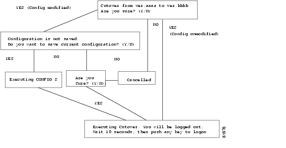
After a new firmware version is downloaded to the EDFA's inactive plane, the CUTOVER command begins executing the new firmware. The cutover process is similar to a cold restart, except that information about control loops is stored and recovered after booting so that the EDFA can resume control where it left off. Alarm reporting can be incorrect during a cutover. Cutoveris approximately 12 seconds.
If any unsaved configuration parameters are present when the cutover command is issued, a prompt appears that permits you to save the modified parameters. All unsaved modified parameters will be lost during the cutover process.
Figure 5-2 CUTOVER Command Diagram
Use Table 5-13 to interpret the CUTOVER command details.
LOAD
Yes
N/A
Download firmware to the EDFA
Explanation:
Enter the LOAD START command to download new firmware. During the download process, feedback consisting of an increasing page count appears every second on the terminal screen ( Example 5-19). Each page represents one loaded 128 byte flash page; there are two cyclic redundancy checks (CRCs)at the end of the load procedure. For a successful load, the CRC will match the Cisco-provided CRC (Cisco provides the CRC with its firmware upgrade).
If during download the rate of updates halts and no CRC is displayed within 10 seconds of the halt, the download has failed.
Note
Example 5-19 LOAD START Command:
0-0>LOAD STARTReady for loading0-0>@LLF0 pages loaded12345...nnnnxxxx xxxxUse Table 5-13 to interpret the LOAD START command results.
Table 5-14 Load Parameters
nnnn
0-9999
Pages loaded; 1 page = 128 bytes
xxxx
CRC
16-bit hex CRC of flash plane, repeated twice
A LOAD ABORT command reverts an EDFA that is waiting for a firmware upload to normal mode. Any firmware file sent to the EDFA is rejected. You must reissue the LOAD START command for the EDFA to take action on a firmware file ( Example 5-19).
Example 5-20 LOAD ABORT Command
0-0>LOAD ABORTAborted0-0>
Note
SETADDR
Explanation:
Enter SETADDR<xx> to assign an address to the EDFA module ( Example 5-21).
Example 5-21 SET ADDR Command:
0-0>SETADDR xyx-y>Use Table 5-14 to interpret and issue SETADDR commands.
Table 5-15 EDFA Address Parameters
x
0-9
First half of EDFA address
y
0-9
Second half of EDFA address
SRESET
N/A
N/A
Software reset for EDFA
Explanation:
The SRESET command reboots the EDFA.
Example 5-22 SRESET Command:
0-0>SRESETLD 1: Temp CompensatedLD 2: Temp Compensated
Caution
After bootup, the current control mode of the EDFA is broadcast. In Example 5-22, the EDFA has the temperature-compensated constant gain mode as the default mode of operation.
Note
!SETADDR
N/A
Yes
Bootstraps the EDFA address
Explanation:
An exclamation point placed at the beginning of the SETADDR command overrides the logon requirement of the EDFA. This allows a new address to be assigned without knowledge of the EDFA's current address. After the confirmation prompt is returned, the user is logged out. In practice, the exclamation point shown in the following example is not echoed back ( Example 5-23).
Example 5-23 !SETADDR Command:
!SETADDR xyx-y>Use Table 5-16 to interpret and issue the !SETADDR command.
Table 5-16 EDFA Address Parameters
x
0-9
First half of EDFA address
y
0-9
Second half of EDFA address
Command Summary
Table 5-17 summarizes all the user commands presented in this chapter. Commands are listed in alphabetical order.
![]()
![]()
![]()
![]()
![]()
![]()
![]()
![]()
Posted: Sun Apr 2 03:18:37 PDT 2006
All contents are Copyright © 1992--2006 Cisco Systems, Inc. All rights reserved.
Important Notices and Privacy Statement.