|
|

Table Of Contents
ONS 15216 EDFA1 Optical Specifications
Upgrading to a Larger Number of Wavelengths
ONS 15216 EDFA1 Electrical Specifications
ONS 15216 EDFA1 Mechanical Specifications
ONS 15216 EDFA1 External Features
ONS 15216 LED Alarm Definitions
Technical Specifications
This chapter discusses the technical specifications of the ONS 15216 EDFA1.
See "Installation" to set up and install the ONS 15216 EDFA1. See "Provisioning and Monitoring" for information about a local serial port or remote connection.
ONS 15216 EDFA1 Optical Specifications
Table 2-1 lists the ONS 15216 optical specifications.
Table 2-1 ONS 15216 Optical Specifications
Input Signal Wavelength in a vacuum
1530 nm to 1563 nm
Input Power (channel total)
-29 dBm to -6 dBm (total all channels)
See the "Maximum Input Power" section and the "Upgrading to a Larger Number of Wavelengths" section for additional information.
Mode of Operation
Unidirectional (two common fibers: one for transmit and one for receive)
Maximum Output Power
17 dBm
Signal Gain per channel
23 dB (+/- 1.25 dB)
Gain Flatness
< 2 dB (Peak to Valley)
Noise Figure
< 6.0 dB
Pump Wavelength
980 nm
Polarization Mode Dispersion (PMD)
< 0.6 ps
Input/Output Optical Return Loss
> 27 dB
Backward amplified spontaneous emission (ASE) power
< -20 dBm
Polarization Sensitivity
<0.5 dB
Automatic Gain Control (AGC)
The ONS 15216 EDFA1 contains active-gain block with automatic-gain control loop to minimize the effects of output power variations per wavelength when adding/deleting wavelengths on the same DWDM ring.
Maximum Input Power
CautionIn the constant-gain mode of operation, the ONS 15216 amplifier is designed to operate up to a maximum input power of -6 dBm. Optical specifications cannot be maintained with an input power greater than -6 dBm. Operating at higher powers causes the pumps to be overdriven. Prolonged periods of operation in this condition can shorten the life time of the ONS 15216 EDFA1.
In this mode, optical attenuators are required to bring total input power to less than -6 dBm.
Upgrading to a Larger Number of Wavelengths
You can ensure a smooth upgrade path from a single channel to the maximum number of channels with a minimum disruption of service if the per-channel power of the single channel is properly set from the start. Set the per-channel power so that at full channel loading the total input power is less than -6 dBm (0.25 mW).
For example, if the maximum number of channels at full loading is 18, then you can calculate the power per channel by dividing .25 mW by 18, which equals .0138 mW. This number (.0138 mW) in logarithmic scale is -18.6 dBm.
Use Table 2-2 to calculate per-channel power as a function of the maximum total number of channels at full loading.
Contact Cisco's Technical Assistance Center (TAC) with any questions or concerns regarding maximum input power or setting the upgrade path.
ONS 15216 EDFA1 Electrical Specifications
The ONS 15216 EDFA1 uses a power supply that meets the electrical specifications listed in Table 2-3.
.
ONS 15216 EDFA1 Mechanical Specifications
Table 2-4 lists the mechanical specifications for the ONS 15216 EDFA1.
ONS 15216 EDFA1 External Features
The ONS 15216 EDFA1 has the following external features:
•
•
•
•
•
•
•
•
•
•
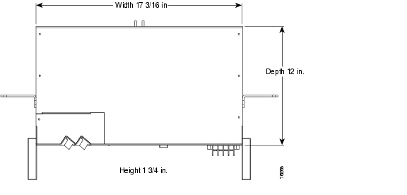
Figure 2-1 shows a mechanical outline of the external features and dimensions of the ONS 15216 EDFA1.
Figure 2-1 ONS 15216 EDFA1 Side View
Figure 2-2 shows the ONS 15216 EDFA1 top view.
Figure 2-2 ONS 15216 EDFA1 Top View
ONS 15216 Front Panel
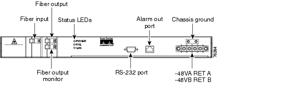
Figure 2-3 displays the ONS 15216 EDFA1 front panel in detail. The front panel provides an all-front access (fibers, power, alarm contact, and management interface) that complies with international standards. Refer to Table 2-5 for information about the front panel features.
Figure 2-3 ONS 15216 EDFA1 Front Panel
Table 2-5 describes the ONS 15216 EDFA1 front panel features.
Table 2-5 ONS 15216 Front Panel Features
ONS 15216 LED Alarm Definitions
The ONS 15216 EDFA1 front panel has three LEDs:
•
The green POWER LED will turn on and off to reflect the following conditions:
–
–
In the OFF condition, the first pair of alarm relay contacts in the RJ-45 connector will change from a normally open condition to a closed condition. The LED and alarm will automatically reset when the condition clears (see the "Alarm Contact Closures" section for additional alarm contact closure information).
•
The red FAIL LED will turn on and off to reflect the following conditions:
–
–
In the ON condition, the second pair of alarm relay contacts in the RJ-45 connector will change from normally open to closed. The LED and alarm will automatically reset when the condition clears (see the "Alarm Contact Closures" section for additional alarm contact closure information).
•
The yellow LED will turn on and off to reflect the following conditions:
–
–
In the ON condition, the third pair of alarm relay contacts in the RJ-45 connector changes from a normally-open condition to a closed condition. The LED and alarm automatically reset when the condition clears (see the "Alarm Contact Closures" section for additional alarm contact closure information).
![]()
![]()
![]()
![]()
![]()
![]()
![]()
![]()
Posted: Sun Apr 2 03:15:34 PDT 2006
All contents are Copyright © 1992--2006 Cisco Systems, Inc. All rights reserved.
Important Notices and Privacy Statement.