|
|

Table Of Contents
Procedure: Set Up Alarm Contacts
Installation-Introductory Commands
Installation-Review and Operational Commands
Installation
This chapter discusses the ONS 15216 EDFA1 installation procedure, which includes power installation, optical cabling, alarm contacts, and installation commands.
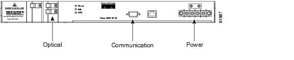
The ONS 15216 EDFA1 is logically divided into the following three sections:
•
Power section (-48V A, RET A, -48V A, RET B, and chassis ground)
•
•
Each section ( Figure 3-1) has an installation procedure in this chapter.
Figure 3-1 Logical Division of the ONS 15216 EDFA1
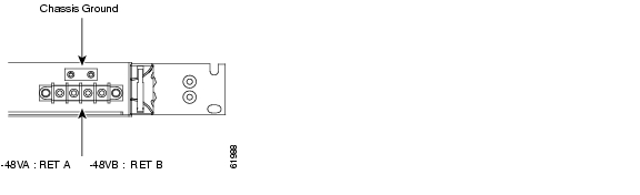
Power Installation
Warning
Caution
Warning
Procedure: Install the ONS 15216 in a Rack
Step 1
Step 2
Step 3
Step 4
Step 5
Step 6
LEDs should now be illuminated on the ONS 15216 EDFA1.
Figure 3-2 Power Connections
.
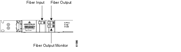
Optical Connections
Procedure: Connect the customer-supplied fiber patch cords to the SC/UPC optical ports
Step 1
Step 2
Step 3
Figure 3-3 ONS 15216 EDFA1 Optical Connections
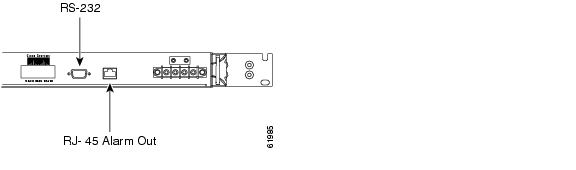
Communication Connections
The ONS 15216 EDFA1 communicates in two ways: alarm contacts (RJ-45) and the serial interface (RS-232).
See the "Local Serial Communication Setup" section for detailed information about the RS-232 serial interface.
Procedure: Set Up Alarm Contacts
Step 1
Step 2
Step 3
See the "Alarm Contact Closures" section and the "ONS 15216 LED Alarm Definitions" section on page 2-7 for further information.
Figure 3-4 ONS 15216 EDFA1 Alarm LEDs
Installation Commands
You can connect to an ONS 15216 locally using a serial connection or remotely using a modem.
See the "Local Serial Communication Setup" section and the "Remote Communication Component Requirements" section for information.
After you establish connection, use the following commands to complete the hardware installation. See Chapter 5, "Command Line Reference" for detailed information about each of these commands. Table 5-17 on page 5-26 summarizes all of the ONS 15216 EDFA1 commands.
Installation-Introductory Commands
You can use the following commands to first establish communication with the ONS 15216 EDFA1 and gain access to additional information about the amplifier.
•
•
•
•
Installation-Review and Operational Commands
You can use the following commands to review the overall status of the EDFA and to make basic configuration changes.
•
•
•
•
•
•
•
–
–
–
–
•
•
![]()
![]()
![]()
![]()
![]()
![]()
![]()
![]()
Posted: Sun Apr 2 03:17:32 PDT 2006
All contents are Copyright © 1992--2006 Cisco Systems, Inc. All rights reserved.
Important Notices and Privacy Statement.