|
|

 |
Caution Make sure that there is no danger that the cables may inadvertently be pulled or cause anyone to trip when in use. |
 |
Note Ports connecting to the user use multimode, single-mode, or a combination of both types of cables depending on the application. Ports on the MUX or DMX use single-mode cables only. |
 |
Warning Only trained and qualified personnel should be allowed to install, replace, or service this equipment. |
|
Note Remove dust covers and blind plugs immediately before you connect the fiber cable. |
|
Note Clean the fiber ferrules as described in the "Cleaning the System" section. Use canned, dry oil-free compressed air only. |
To connect a WCM to MUX and DMX modules, follow these steps:
Step 2 Remove the dust cover from the other end of the jumper and the blind plug from the corresponding MUX connector. For example, if you interconnect the seventh WCM, remove the blind plug from the MUX connector labeled 7. (See Figure 5-1.)

Step 3 Remove the blind plug from the WCM connector labeled R/R (remote receiver) and the dust cover from one end of a short jumper. Connect the MiniSC plug to the open connector.
Step 4 Remove the dust cover from the other end of the jumper and the blind plug from the corresponding DMX connector. For example, if you interconnect the seventh WCM, remove the blind plug from the DMX connector labeled 7. (See Figure 5-1.)
Step 5 Place the fiber-optic cables in the cable holder at the bottom of the chassis.
Repeat these steps with all other WCMs of the main chassis and extension chassis.
To connect a BSM to MUX and DMX modules, follow these steps:
Step 2 Remove the dust cover from the other end of the jumper and the blind plug from the BSM connector labeled M1. (Use M1 if you are routing the MUX of the primary chassis.) Connect the MiniSC plug to the open connector of the BSM, as shown in Figure 5-2.
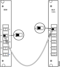
Step 3 Remove the dust cover from one end of a jumper and the blind plug from the DMX connector labeled D1. (Use D1 if you are routing the DMX of the primary chassis.) Connect the MiniSC plug to the open connector.
Step 4 Remove the dust cover from the other end of the jumper and the blind plug from the BSM connector labeled D1. (Use D1 if you are routing the DMX of the primary chassis.) Connect the MiniSC plug to the open connector of the BSM, as shown in Figure 5-3.

Step 5 Place the fiber-optic cables in the cable holder of the primary and extension chassis and the rack at the side of both chassis.
|
Note If you have an RSM installed, proceed to the "Connec ting a BSM to an RSM" section. Otherwise skip to the "Connec ting Remote Lines to a BSM" section |
To connect a BSM to an optional RSM, follow these steps:
Step 2 Remove the dust cover from the other end of the blind plug from the RSM connector labeled M. Connect the MiniSC plug to the open connector of the RSM, as shown in Figure 5-4.
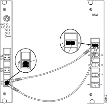
Step 3 Remove the dust cover from one end of a jumper and the blind plug from the BSM connector labeled D. Connect the MiniSC plug to the open connector.
Step 4 Remove the dust cover from the other end of the jumper and the blind plug from the RSM labeled D. Connect the plug to the open connector of the RSM, as shown in Figure 5-4.
Step 5 Place the fiber-optic cables in the cable holder of the primary and extension chassis and the rack at the side of both chassis.
|
Note If you have a BSM installed, proceed to the "Connec ting Remote Lines to a BSM" section. Otherwise skip to the "Connec ting Remote Lines to RSMs" section. |
To connect remote lines to a BSM, follow these steps:
Step 2 Remove the blind plug from the BSM connector labeled M. Connect the cleaned plug to the open connector of the BSM. (See Figure 5-5.)
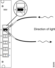
Step 3 Remove the dust cover from the MiniSC plug of the remote receiver fiber line, and clean the fiber as described in the "Cleaning the Connectors" section.
Step 4 Remove the blind plug from the BSM connector labeled D. Connect the cleaned plug to the open connector of the BSM, as shown in Figure 5-5.
Step 5 Place the fiber-optic cables in the cable holder of the primary and extension chassis and the rack at the side of both chassis.
|
Note If you have an optional RSM installed, proceed to the "Connec ting Remote Lines to RSMs" section. Otherwise skip to the "Connec ting Local Lines to WCMs" section. |
To connect remote lines to an RSM, follow these steps:
Step 2 Remove the blind plug from the RSM connector labeled A/T. Connect the cleaned plug to the open connector of the RSM, as shown in Figure 5-6.

Step 3 Remove the dust cover from the MiniSC plug of the remote receiver fiber of line A, and clean the fiber as described in "Cleaning the Connectors" section.
Step 4 Remove the blind plug from the RSM connector labeled A/R. Connect the cleaned plug to the open connector of the RSM. (See Figure 5-6.)
Step 5 Remove the dust cover from the MiniSC plug of the remote transmission fiber of line B, and clean the fiber as described in "Cleaning the Connectors" section.
Step 6 Remove the blind plug from the RSM connector labeled B/T. Connect the cleaned plug to the open connector of the RSM. (See Figure 5-6.)
Step 7 Remove the dust cover from the MiniSC plug of the remote receiver fiber of line B, and clean the fiber as described in "Cleaning the Connectors" section.
Step 8 Remove the blind plug from the RSM connector labeled B/R. Connect the cleaned plug to the open connector of the RSM. (See Figure 5-6.)
Step 9 Place the fiber-optic cables in the cable holder of the primary and extension chassis and the rack at the side of both chassis.
To connect local lines to a WCM, follow these steps:
Step 2 Remove the blind plug from the WCM connector labeled L/R. Connect the cleaned plug to the open connector of the WCM. (See Figure 5-7.)
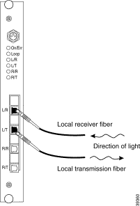
Step 3 Remove the dust cover from the MiniSC plug of the local transmission fiber and clean the fiber as described in "Cleaning the Connectors" section.
Step 4 Remove the blind plug from the WCM connector labeled L/T. Connect the cleaned plug to the open connector of the WCM, as shown in Figure 5-7.
Step 5 Place the fiber-optic cables in the cable holder of the primary chassis and extension chassis and the rack at the side of both chassis.
Step 6 Mount the acrylic cover on the front of the chassis.
When connecting a fiber channel or Gigabit Ethernet port to a high-speed transparent WCM on the Cisco Metro 1500 series system, you must ensure that the optical power levels from the fiber channel or Gigabit Ethernet transmitter do not overdrive the local receiver (L/R) port on the WCM. To avoid an overdrive condition, insert an optical attenuation of 5 dB between the fiber channel or Gigabit Ethernet transmitter and the L/R port on the WCM. You can implement this attenuation with either an attenuating single-mode patch cable assembly or an attenuating coupler, which are described in the following sections.
An attenuating single-mode patch cable is a 9.84-ft (3 m) fiber-optic jumper cable with a built-in attenuation of 5 db. (See Figure 5-8.)

The attenuating single-mode patch cable assembly should contain Corning SMF-28 or equivalent single-mode fiber.
As an alternative to the attenuating single-mode patch cable, you can use a 5-dB attenuating coupler. (See Figure 5-9.)
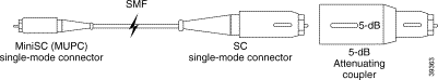
Figure 5-9 shows a conventional MiniSC to SC patch cable, plus the attenuating coupler, which achieves the same effect as the attenuating single-mode patch cable assembly with the built-in attenuation.
|
Caution When connecting Cisco Metro 1500 series systems, you must adhere to the minimum remote link budget, as called out in Table A-9. If you do not adhere to this minimum budget, you might damage the receivers of the channel cards. This damage can only be repaired at the factory and is not covered by the warranty. |
The optical isolator minimizes optical back reflection. Optical back reflection is common in fiber-based transmissions. Back reflection is a small amount of light that is reflected back towards the transmitting optical component. The optical isolator absorbs this reflected light so that the transmitting optical component operates with minimal interference.
The optical isolator is connected directly to a jumper that extends from the remote connection of the WCM. The optical isolator sits between the WCM and the remote (or trunk) fiber. (See Figure 5-10.)

To connect the optical isolator, follow these guidelines:
Table 5-1 lists the tests required for the remote link and the equipment required to perform each test.
| Tests | Equipment Required |
|---|---|
Optical link loss 1550 nm specified in dBm referenced to 1 mW |
|
Distance specified in km | OTDR |
Optical return loss 1550 nm specified in dB | Reflectometer |
| 1OTDR = optical time domain reflectometer |
To test a remote optical communications link, follow these steps:
Step 2 Supply a modulated light to the local receiver of the WCM.
This modulated light switches on the local receiver and the remote transmitter of the local system. The green L/R LED should be on. If the modulated light does not match the clock recovery frequency, assuming a clock recovery is installed and enabled, the Error Indicator LED will be red.
Step 3 Set the remote loopback of the corresponding WCM of the remote system.
The orange loop LED of the WCM in the remote system should be on. The remote receiver, the remote transmitter, and the local transmitter should operate and loopback the received signal to the local system. The R/R, R/T, and L/T LEDs should be on. If the modulated light does not match the clock-recovery frequency, assuming a clock recovery is installed and enabled, the R/R LED will be red. The remote receiver of the local system sees the signal and transfers it to the local transmitter. The WCM in the local system should have the L/T, L/R, R/T, and R/R LEDs on.
|
Note If your test results deviate from these results and you cannot correct the problem, contact your Cisco service representative. |
![]()
![]()
![]()
![]()
![]()
![]()
![]()
![]()
Posted: Fri Aug 2 18:20:46 PDT 2002
All contents are Copyright © 1992--2002 Cisco Systems, Inc. All rights reserved.
Important Notices and Privacy Statement.