|
|

This chapter describes how to install modules in the Cisco Metro 1500 series system. The modules are installed and removed using the same basic steps. This chapter includes the following sections:
The Cisco Metro 1500 series system can be equipped with the following modules, which are described in "Product Overview."
| Modules | Section Name and Page Number |
|---|---|
WCMs | |
MUX and DMX | |
BSM | |
RSM | |
TDM4E |
 |
Note For information on connecting the modules after they have been installed, see "Connecting Optical Cables." |
Before installing the modules, see "Preparing for Installation." Also note the following warnings:
 |
Warning Before you install, operate, or service the system, read the Site Preparation and Safety Guide. This guide contains important safety information you should know before working with the system. |
 |
Warning Only trained and qualified personnel should be allowed to install, replace, or service this equipment. |
The following tools are required for installing modules in the chassis:
 |
Warning During this procedure, wear grounding wrist straps to avoid ESD damage to the card. Do not directly touch the backplane with your hand or any metal tool, or you could shock yourself. |
This section describes how to add and replace modules without interrupting unit operation.
 |
Note Before connecting the fiber cable, remove the dust covers and blind plugs, and clean the fiber ferrules. The minimum bend radius of optical fiber cables is about 30 to 50 nm. Avoid tightening or pressuring fibers. |
To install modules, follow these steps:
Step 2 Remove the two screws from the blank filler module and remove the module.
Step 3 Take the new module from the shipping container and use canned, dry, oil-free, compressed air to blow off any possible dust particles.
Step 4 Insert the module carefully into the chassis slot while guiding the upper and lower edges of the module in the tracks until its connectors come into contact with the backplane connectors.
Step 5 Hold the module in position after making full contact and use the two screws on the front panel of the module to secure it in the housing. When the module is in contact with the backplane, the power LED turns green.
 |
Note The red LED flashes during the initialization process. |
Step 6 Connect a MiniSC jumper to the WCM labeled R/T.
Step 7 Connect the other end of the jumper to the corresponding connector of the MUX. For example, if you interconnect the seventh WCM, use the MUX connector labeled 7, as shown in Figure 4-1.
 |
Note The DMX in Figure 4-1 is shown for reference only. |
.
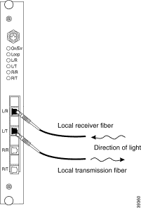
Step 8 Connect the MiniSC plug of the local receiver fiber line to the WCM labeled L/R, as shown in Figure 4-2.

Step 9 Connect the MiniSC plug of the local transmission fiber line to the WCM labeled L/T, as shown in Figure 4-2.
Step 10 Place the fiber-optic cables in the cable holder of the chassis and the rack at the side of the chassis.
Step 11 Mount the acrylic cover on the front of the chassis.
Step 12 Save the blank filler panel with the packaging material.
If you applied a local signal to the added channel, the green L/R LED and green R/T LED should both be on.
When the remote lines from the DMX to the MUX are also connected, the remote transmitter light is fed from the other Cisco Metro 1500 series chassis, and the green R/R LED of the active line and green L/T LED should both be on.
 |
Note If you have any problems with the installation, contact your Cisco service representative immediately. |
To remove a module from your unit without interrupting system operation, follow these steps:
Step 2 Remove all jumpers from the desired module and install appropriate dust covers on the fiber cable connectors and the blind plugs into the module connectors.
Step 3 Remove the remote line jumpers from the desired MUX and DMX connectors. Install appropriate dust covers on the fiber cable connectors and the plugs into the MUX and DMX connectors.
Step 4 Remove the two screws that connect the protective front panel of the desired module to the chassis.
Step 5 Remove the module carefully.
Step 6 Reinstall the blank filler module.
Step 7 Place the removed module in a container appropriate for shipping and storage.
Step 8 Mount the acrylic cover on the front of the chassis.
![]()
![]()
![]()
![]()
![]()
![]()
![]()
![]()
Posted: Fri Aug 2 15:04:32 PDT 2002
All contents are Copyright © 1992--2002 Cisco Systems, Inc. All rights reserved.
Important Notices and Privacy Statement.